CN216645738U - Tool for checking air tightness of oil pipe - Google Patents
Tool for checking air tightness of oil pipe Download PDFInfo
- Publication number
- CN216645738U CN216645738U CN202220126772.XU CN202220126772U CN216645738U CN 216645738 U CN216645738 U CN 216645738U CN 202220126772 U CN202220126772 U CN 202220126772U CN 216645738 U CN216645738 U CN 216645738U
- Authority
- CN
- China
- Prior art keywords
- fixed
- oil pipe
- cylinder
- sealing ring
- bottom plate
- Prior art date
- Legal status (The legal status is an assumption and is not a legal conclusion. Google has not performed a legal analysis and makes no representation as to the accuracy of the status listed.)
- Active
Links
Images


Landscapes
- Examining Or Testing Airtightness (AREA)
Abstract
The utility model discloses an oil pipe air tightness detection tool, and relates to the technical field of oil pipe detection. The device comprises a supporting table, wherein a detection mechanism for testing is installed at one end of the top of the supporting table, the detection mechanism comprises a water tank, a fixed bottom plate, a second air cylinder, an air valve joint, a first sealing ring, a supporting block, a third air cylinder and a second sealing ring, and the fixed bottom plate is arranged on the inner side of the water tank. According to the utility model, through the matching of a series of structures such as the water tank, the second air cylinder, the air valve joint, the first sealing ring, the third air cylinder and the second sealing ring, the tool can accurately judge whether the sealing property of the oil pipe is qualified or not through whether bubbles are generated in water or not when in use, and through the matching of the fixed shell, the connecting block, the supporting plate and the workpiece placing plate, the placing mechanism can be adjusted in height according to the height of an operator when in use, so that a user can place the tested oil pipe conveniently.
Description
Technical Field
The utility model belongs to the technical field of oil pipe detection, and particularly relates to an oil pipe air tightness detection tool.
Background
Along with the continuous development and the progress of society, detection device to various parts is more and more meticulous, and oil pipe is the pipeline that is used for carrying liquid material such as fluid, need detect whether the leakproofness is qualified through the gas tightness after its processing is accomplished, and current frock is not accurate enough to oil pipe's detection when carrying out the use, and can not be convenient for place the oil pipe that detects the completion when using.
SUMMERY OF THE UTILITY MODEL
The utility model aims to provide an oil pipe air tightness detection tool, which aims to solve the existing problems that: the detection of current frock to oil pipe when carrying out the use is accurate inadequately.
In order to solve the technical problems, the utility model is realized by the following technical scheme: the oil pipe air tightness gauge tool comprises a supporting table, wherein a detection mechanism for testing is installed at one end of the top of the supporting table, the detection mechanism comprises a water tank, a fixed bottom plate, a second air cylinder, an air valve joint, a first sealing ring, a supporting block, a third air cylinder and a second sealing ring, the fixed bottom plate is arranged on the inner side of the water tank, the second air cylinder is fixed at one end of the top of the fixed bottom plate, the output end of the second air cylinder is connected with a fixed column, the first sealing ring is fixed at one end, away from the second air cylinder, of the fixed column, the air valve joint is arranged at the top of the fixed column, a vent groove is formed in the bottom of the air valve joint, the other end of the vent groove is located on the inner side of the first sealing ring, the third air cylinder is fixed at one side of the other end of the top of the fixed bottom plate, the output end of the third air cylinder is connected with a clamping column, and the second sealing ring is fixed at one side, away from the third air cylinder, of the clamping column,
the top of PMKD still is fixed with the supporting shoe for fix a position oil pipe, the inside of basin is still installed and is used for driving PMKD to go up and down the adjusting part.
Furthermore, the adjusting assembly comprises a supporting machine, a first air cylinder and a connecting plate, the bottom of the supporting machine is fixed with the water tank, the first air cylinder is fixed at the top of the supporting machine, the connecting plate is fixed at the output end of the first air cylinder and positioned on the inner side of the supporting machine, and the bottom of the connecting plate is fixed with the fixed bottom plate.
Furthermore, a placing mechanism for storing the workpieces is installed at the other end of the top of the supporting platform.
Further, the placer includes that the board is placed to set casing, connecting block, backup pad, work piece, locating piece and spring, two the bottom of set casing all is fixed with a supporting bench, the inside sliding connection on set casing top has the connecting block, the inside of set casing and the bottom that is located the connecting block are fixed with the spring, the internally mounted of set casing has the buckle subassembly that is used for advancing the location to the connecting block, the top of connecting block is fixed with the backup pad, the inside sliding connection on backup pad top has the locating piece, the top of locating piece is fixed with the work piece and places the board.
Further, buckle component includes spacing post and spliced pole, equal sliding connection between spacing post and the set casing, between spacing post and the connecting block, two threaded connection has the spliced pole between the spacing post.
Further, a plurality of through-holes have been seted up to the inside equipartition of connecting block, spacing post passes through-hole sliding connection with the connecting block.
The utility model has the following beneficial effects:
1. according to the tool, through the matching of a series of structures such as the water tank, the second air cylinder, the air valve joint, the first sealing ring, the third air cylinder and the second sealing ring, the tool can accurately judge whether the sealing performance of the oil pipe is qualified or not through whether bubbles are generated in water or not when the tool is used.
2. According to the utility model, through the matching of the fixing shell, the connecting block, the supporting plate and the workpiece placing plate, the placing mechanism can be adjusted in height according to the height of an operator when in use, so that a user can place an oil pipe after testing conveniently.
Drawings
In order to more clearly illustrate the technical solutions of the embodiments of the present invention, the drawings used in the description of the embodiments will be briefly introduced below, and it is obvious that the drawings in the following description are only some embodiments of the present invention, and it is obvious for those skilled in the art that other drawings can be obtained according to the drawings without creative efforts.
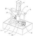
FIG. 1 is a schematic structural view of the present invention as a whole;
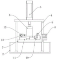
FIG. 2 is a schematic structural diagram of the detecting mechanism of the present invention;
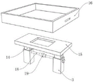
FIG. 3 is a schematic view of a connection structure of the supporting machine and the first cylinder according to the present invention;
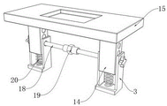
FIG. 4 is a schematic view of the placement mechanism of the present invention;
FIG. 5 is a schematic view of the connection structure of the support plate and the connection block according to the present invention;
FIG. 6 is a schematic view of the internal structure of the fixing case according to the present invention;
fig. 7 is a schematic view of the connection structure of the connection column and the limit column of the present invention.
In the drawings, the components represented by the respective reference numerals are listed below:
1. a support table; 2. a water tank; 3. a stationary housing; 4. a supporting machine; 5. a first cylinder; 6. a connecting plate; 7. fixing the bottom plate; 8. a second cylinder; 9. an air valve joint; 10. a first seal ring; 11. a support block; 12. a third cylinder; 13. a second seal ring; 14. connecting blocks; 15. a support plate; 16. a workpiece placing plate; 17. positioning blocks; 18. a limiting column; 19. connecting columns; 20. a spring.
Detailed Description
The technical solutions in the embodiments of the present invention will be clearly and completely described below with reference to the drawings in the embodiments of the present invention, and it is obvious that the described embodiments are only a part of the embodiments of the present invention, and not all of the embodiments. All other embodiments, which can be derived by a person skilled in the art from the embodiments given herein without making any creative effort, shall fall within the protection scope of the present invention.
Referring to fig. 1-7, the utility model relates to an oil pipe airtightness detection tool, which comprises a support table 1, wherein a detection mechanism for testing is installed at one end of the top of the support table 1, the detection mechanism comprises a water tank 2, a fixed bottom plate 7, a second cylinder 8, an air valve joint 9, a first sealing ring 10, a support block 11, a third cylinder 12 and a second sealing ring 13, the fixed bottom plate 7 is arranged on the inner side of the water tank 2, the second cylinder 8 is fixed at one end of the top of the fixed bottom plate 7, the output end of the second cylinder 8 is connected with a fixed column, the first sealing ring 10 is fixed at one end of the fixed column far away from the second cylinder 8, the air valve joint 9 is arranged at the top of the fixed column, a vent groove is arranged at the bottom of the air valve joint 9, the other end of the vent groove is positioned on the inner side of the first sealing ring 10, so that air entering through the air valve joint 9 can enter the interior of the vent groove, on the inside of the first sealing ring 10 through the vent groove;
a third cylinder 12 is fixed on one side of the other end of the top of the fixed bottom plate 7, the output end of the third cylinder 12 is connected with a clamping column, a second sealing ring 13 is fixed on one side of the clamping column far away from the third cylinder 12, and then two ends of an oil pipe can be sealed through the first sealing ring 10 and the second sealing ring 13, so that a sealing space is formed;
furthermore, the top of the fixed bottom plate 7 is also fixed with a supporting block 11 for positioning the position of the oil pipe, the inside of the water tank 2 is also provided with an adjusting component for driving the fixed bottom plate 7 to lift, the adjusting component comprises a support machine 4, a first cylinder 5 and a connecting plate 6, the bottom of the support machine 4 is fixed with the water tank 2, the top of the support machine 4 is fixed with the first cylinder 5, so that the position of the first cylinder 5 can be stably fixed through the support machine 4, the output end of the first cylinder 5 and the inner side of the support machine 4 are fixed with the connecting plate 6, the bottom of the connecting plate 6 is fixed with the fixed bottom plate 7, and further the fixed bottom plate 7 can be driven to lift through the connecting plate 6;
during operation, water is injected into the water tank 2 to reach three-quarters of the water, an oil pipe to be detected is placed on the inner side of the supporting block 11, the first sealing ring 10 is driven by the second cylinder 8 to seal one end of the oil pipe, meanwhile, the second sealing ring 13 is driven by the third cylinder 12 to seal the other end of the oil pipe, so that the oil pipe is tightly pressed, the inside of the oil pipe is in a sealed state, the connecting plate 6 is driven by the first cylinder 5 to descend, the connecting plate 6 drives the fixing bottom plate 7 to descend, the fixing bottom plate 7 drives the fixing oil pipe to descend to enter the water injected into the water tank 2, the oil pipe is submerged by the water, gas is injected into the inside of the oil pipe through the gas valve joint 9 and the vent groove to detect whether bubbles emerge in the water, if bubbles emerge, the air tightness of the oil pipe is unqualified, leakage can be generated, and if no bubbles emerge, the air tightness of the oil pipe is qualified.
The other end of the top of the supporting table 1 is provided with a placing mechanism for storing workpieces, the placing machine comprises fixed shells 3, connecting blocks 14, supporting plates 15, workpiece placing plates 16, positioning blocks 17 and springs 20, the bottoms of the two fixed shells 3 are fixed with the supporting table 1, the connecting blocks 14 are connected inside the top ends of the fixed shells 3 in a sliding manner, the springs 20 are fixed inside the fixed shells 3 and at the bottoms of the connecting blocks 14, a plurality of through holes are uniformly distributed in the connecting blocks 14, buckle assemblies for positioning the connecting blocks 14 are installed inside the fixed shells 3, so that the connecting blocks 14 can be adjusted in height inside the fixed shells 3 and can be used for positioning the adjusted connecting blocks 14 through the buckle assemblies, the supporting plates 15 are fixed at the tops of the connecting blocks 14, the positioning blocks 17 are connected inside the tops of the supporting plates 15 in a sliding manner, and the workpiece placing plates 16 are fixed at the tops of the positioning blocks 17, the detected oil pipe can be stored through the workpiece placing plate 16;
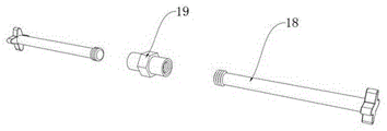
further, the buckle assembly comprises a limiting column 18 and a connecting column 19, the limiting column 18 is in sliding connection with the fixed shell 3, the limiting column 18 is in sliding connection with the connecting block 14, and the connecting column 19 is in threaded connection between the two limiting columns 18, so that the two limiting columns 18 are fixed through the connecting column 19, and the limiting columns 18 are prevented from falling off;
when needing to be adjusted, through the height of adjustment backup pad 15 to suitable position, make backup pad 15 drive connecting block 14 and go up and down when adjusting, support in advance through the pressurization elasticity of spring 20 simultaneously, install spacing post 18 in the inside of set casing 3 and connecting block 14 through the sliding connection between with set casing 3, between spacing post 18 and the connecting block 14, and then fix the height of connecting block 14, then fix spacing post 18 through the threaded connection of spacing post 18 with spliced pole 19, prevent that spacing post 18 from dropping, then place board 16 and place the top at backup pad 15 with the work piece through the sliding connection of locating piece 17 with backup pad 15, and then place board 16 through the work piece and store the oil pipe that has detected, and can be convenient for carry.
In the description herein, references to the description of "one embodiment," "an example," "a specific example" or the like are intended to mean that a particular feature, structure, material, or characteristic described in connection with the embodiment or example is included in at least one embodiment or example of the utility model. In this specification, the schematic representations of the terms used above do not necessarily refer to the same embodiment or example. Furthermore, the particular features, structures, materials, or characteristics described may be combined in any suitable manner in any one or more embodiments or examples.
The preferred embodiments of the utility model disclosed above are intended to be illustrative only. The preferred embodiments are not intended to be exhaustive or to limit the utility model to the precise embodiments disclosed. Obviously, many modifications and variations are possible in light of the above teaching. The embodiments were chosen and described in order to best explain the principles of the utility model and the practical application, to thereby enable others skilled in the art to best utilize the utility model. The utility model is limited only by the claims and their full scope and equivalents.
Claims (6)
1. Utensil frock is examined to oil pipe gas tightness, its characterized in that: the device comprises a supporting table (1), wherein a detection mechanism for testing is installed at one end of the top of the supporting table (1), the detection mechanism comprises a water tank (2), a fixed bottom plate (7), a second cylinder (8), an air valve joint (9), a first sealing ring (10), a supporting block (11), a third cylinder (12) and a second sealing ring (13), the fixed bottom plate (7) is arranged on the inner side of the water tank (2), the second cylinder (8) is fixed at one end of the top of the fixed bottom plate (7), a fixing column is connected to the output end of the second cylinder (8), the first sealing ring (10) is fixed at one end of the fixing column, which is far away from the second cylinder (8), the air valve joint (9) is arranged at the top of the fixing column, an air vent groove is formed in the bottom of the air valve joint (9), and the other end of the air vent groove is located on the inner side of the first sealing ring (10), a third cylinder (12) is fixed on one side of the other end of the top of the fixed bottom plate (7), the output end of the third cylinder (12) is connected with a clamping column, and a second sealing ring (13) is fixed on one side, far away from the third cylinder (12), of the clamping column;
the top of the fixed bottom plate (7) is also fixed with a supporting block (11) for positioning the position of the oil pipe, and an adjusting component for driving the fixed bottom plate (7) to ascend and descend is further installed inside the water tank (2).
2. The oil pipe air tightness testing fixture tool according to claim 1, characterized in that: the adjusting component comprises a supporting machine (4), a first air cylinder (5) and a connecting plate (6), the bottom of the supporting machine (4) is fixed with the water tank (2), the top of the supporting machine (4) is fixed with the first air cylinder (5), the output end of the first air cylinder (5) is fixed with the connecting plate (6) on the inner side of the supporting machine (4), and the bottom of the connecting plate (6) is fixed with the fixed bottom plate (7).
3. The oil pipe air tightness testing fixture tool according to claim 1, characterized in that: the other end of the top of the supporting table (1) is provided with a placing mechanism for storing workpieces.
4. The oil pipe air tightness testing fixture tool according to claim 3, characterized in that: the placer includes that set casing (3), connecting block (14), backup pad (15), work piece place board (16), locating piece (17) and spring (20), two the bottom of set casing (3) all is fixed with brace table (1), the inside sliding connection on set casing (3) top has connecting block (14), the inside of set casing (3) and the bottom that is located connecting block (14) are fixed with spring (20), the internally mounted of set casing (3) has the buckle subassembly that is used for going on fixing a position connecting block (14), the top of connecting block (14) is fixed with backup pad (15), the inside sliding connection on backup pad (15) top has locating piece (17), the top of locating piece (17) is fixed with the work piece and places board (16).
5. The oil pipe air tightness testing fixture tool according to claim 4, characterized in that: the buckle component comprises a limiting column (18) and a connecting column (19), wherein the limiting column (18) and the fixed shell (3) are connected in a sliding mode, the limiting column (18) and the connecting block (14) are connected in a sliding mode, and the connecting column (19) is connected between the limiting column (18) in a threaded mode.
6. The oil pipe airtightness testing fixture tool according to claim 5, characterized in that: a plurality of through holes are uniformly distributed in the connecting block (14), and the limiting columns (18) are connected with the connecting block (14) in a sliding mode through the through holes.
Priority Applications (1)
| Application Number | Priority Date | Filing Date | Title |
|---|---|---|---|
| CN202220126772.XU CN216645738U (en) | 2022-01-18 | 2022-01-18 | Tool for checking air tightness of oil pipe |
Applications Claiming Priority (1)
| Application Number | Priority Date | Filing Date | Title |
|---|---|---|---|
| CN202220126772.XU CN216645738U (en) | 2022-01-18 | 2022-01-18 | Tool for checking air tightness of oil pipe |
Publications (1)
| Publication Number | Publication Date |
|---|---|
| CN216645738U true CN216645738U (en) | 2022-05-31 |
Family
ID=81727497
Family Applications (1)
| Application Number | Title | Priority Date | Filing Date |
|---|---|---|---|
| CN202220126772.XU Active CN216645738U (en) | 2022-01-18 | 2022-01-18 | Tool for checking air tightness of oil pipe |
Country Status (1)
| Country | Link |
|---|---|
| CN (1) | CN216645738U (en) |
-
2022
- 2022-01-18 CN CN202220126772.XU patent/CN216645738U/en active Active
Similar Documents
| Publication | Publication Date | Title |
|---|---|---|
| CN206504833U (en) | A kind of seal welding leak-checking apparatus of pressure limiting cover plate | |
| CN218647017U (en) | Automatic testing jig for timing | |
| CN216645738U (en) | Tool for checking air tightness of oil pipe | |
| CN110646146A (en) | New energy automobile battery case shell gas tightness detection device | |
| CN203083784U (en) | Hydraulically compacted-type leakage testing device | |
| CN112326152A (en) | Electronic component airtightness testing device | |
| CN111473926A (en) | Manifold airtightness detection device | |
| CN110749401A (en) | Leak hunting smelting tool | |
| CN115876404A (en) | Sealing detection device capable of simulating various complex environments | |
| CN210981659U (en) | Leak hunting smelting tool | |
| CN115219115A (en) | Stable gas measurement device and gas measurement method | |
| CN215811461U (en) | Pipe fitting gas tightness check out test set | |
| CN114646437A (en) | Expansion tank gas tightness check out test set for car | |
| CN209992122U (en) | Airtightness testing mechanism | |
| CN220288916U (en) | Leakage detection equipment of corrugated pipe energy accumulator | |
| CN218646522U (en) | Metal can air tightness detection device | |
| CN214667469U (en) | Fixed pincers leakage detection device | |
| CN220912581U (en) | Leak detection equipment for automobile cylinder body | |
| CN210400681U (en) | Device for detecting contact pressure of assembly joint surface | |
| CN211317633U (en) | Sealing test fixture for transmission gear of hydraulic pump | |
| CN112763146A (en) | Bearing jig for water tightness test, test device and test method | |
| CN112629855A (en) | Bearing sealing performance detection device | |
| CN215414231U (en) | High-precision air tightness detection device | |
| CN216081924U (en) | Water separator air tightness performance test equipment | |
| CN218443948U (en) | Experimental device for simulating different pressures and gas environments |
Legal Events
| Date | Code | Title | Description |
|---|---|---|---|
| GR01 | Patent grant | ||
| GR01 | Patent grant |