CN216642543U - Lubricating bearing body structure for lubricating thin oil and rotating grease - Google Patents
Lubricating bearing body structure for lubricating thin oil and rotating grease Download PDFInfo
- Publication number
- CN216642543U CN216642543U CN202123357590.8U CN202123357590U CN216642543U CN 216642543 U CN216642543 U CN 216642543U CN 202123357590 U CN202123357590 U CN 202123357590U CN 216642543 U CN216642543 U CN 216642543U
- Authority
- CN
- China
- Prior art keywords
- bearing
- oil
- sleeve
- gland
- grease
- Prior art date
- Legal status (The legal status is an assumption and is not a legal conclusion. Google has not performed a legal analysis and makes no representation as to the accuracy of the status listed.)
- Active
Links
Images


Landscapes
- Rolling Contact Bearings (AREA)
Abstract
The utility model discloses a thin oil lubrication grease-transfer lubrication bearing body structure, which comprises a bearing box, a pump shaft, a bearing front gland, a bearing rear gland, a bearing and an anti-splash baffle, wherein the anti-splash baffle comprises a bearing outer ring pressing plate and an anti-splash sleeve, the shape of the bearing outer ring pressing plate is matched with that of the bearing outer ring, the front end and the rear end of the anti-splash sleeve are arranged in a penetrating manner, the diameter of the front port of the anti-splash sleeve is larger than that of the rear port, and the front end of the anti-splash sleeve is fixedly connected with the inner end of the bearing outer ring pressing plate; the anti-splashing sleeve is sleeved on the pump shaft and positioned between the bearing and the bearing rear gland, and the bearing outer ring pressing plate is abutted against the bearing outer ring through the cylindrical end part of the bearing rear gland; the bearing front pressure cover is provided with the grease lubrication oil filling hole which is communicated with the inner part of the bearing box body.
Description
Technical Field
The utility model relates to the technical field of bearing bodies of centrifugal pumps, in particular to a bearing body structure for lubricating grease by using thin oil.
Background
Along with the development of industry, the application of centrifugal pump is more extensive, for guaranteeing the even running of centrifugal pump, need lubricate the bearing of centrifugal pump, under the operating mode condition of difference, the lubrication mode is different, and the bearing lubrication mode that often adopts includes thin oil lubrication and fat lubrication, and thin oil lubrication generally is applicable to the operating environment of light load, high speed, high temperature, and fat lubrication generally is applicable to heavily loaded, low-speed, microthermal operating environment, and different lubrication mode adopts different bearing body structures.
The centrifugal pump is characterized in that a thin oil lubricating mode is possibly designed in the earlier stage by a centrifugal pump manufacturer, a thin oil lubricating bearing body structure comprises a bearing box, a pump shaft, a bearing front gland, a bearing rear gland and a bearing, the pump shaft is connected with the bearing box through the bearing, the bearing front gland is arranged on the front side of the bearing, the bearing rear gland is arranged on the rear side of the bearing, the pump shaft penetrates through the bearing front gland and the bearing rear gland, and the bearing front gland and the bearing rear gland are fixedly connected with the bearing box respectively.
However, according to the field working conditions (for example, there are oil leakage risks and environmental pollution) the customer needs to change the grease lubrication mode, and at this time, the model needs to be redesigned and the new assembly is needed, which increases the manufacturing cost and results in a long supply period.
Disclosure of Invention
The utility model aims to overcome the defects in the prior art and provides the lubricating bearing body structure with the advantages of simple structure, low manufacturing cost, convenience in assembly, short supply period and high universality.
The technical scheme adopted by the utility model for solving the technical problems is as follows:
the utility model provides a thin oil lubrication changes lubricated bearing body structure of fat, gland and bearing behind gland, the bearing before bearing box, pump shaft, bearing, its characterized in that: the anti-splash baffle comprises a bearing outer ring pressing plate and an anti-splash sleeve, wherein the shape of the bearing outer ring pressing plate is matched with that of the bearing outer ring, the front end and the rear end of the anti-splash sleeve are arranged in a penetrating mode, the diameter of the front end opening of the anti-splash sleeve is larger than that of the rear end opening, and the front end of the anti-splash sleeve is fixedly connected with the inner end of the bearing outer ring pressing plate;
the anti-splashing sleeve is sleeved on the pump shaft and positioned between the bearing and the bearing rear gland, and the bearing outer ring pressing plate is abutted against the bearing outer ring through the cylindrical end part of the bearing rear gland;
the grease lubrication oil filling hole is formed in the front pressure cover of the bearing, the grease lubrication oil filling hole is communicated with the inside of the bearing box body, the splash-proof baffle is arranged, the bearing outer ring pressing plate is pressed against the bearing outer ring through the rear pressure cover of the bearing, the splash-proof sleeve is used for preventing lubricating grease from splashing, the thin oil lubrication bearing body is converted into the grease lubrication bearing body, the original parts can be continuously used, the model does not need to be thrown again, the manufacturing cost is reduced, the material supply period is shortened, when the thin oil lubrication bearing body needs to be reused, the rear pressure cover of the bearing is detached, the splash-proof baffle is taken out, and the grease lubrication bearing body can be converted into the thin oil lubrication bearing body.
The anti-splash sleeve comprises a support sleeve and an oil baffle plate, the front end of the support sleeve is fixedly connected with the inner end of the bearing outer ring pressing plate, the rear end of the support sleeve is fixedly connected with the outer end of the oil baffle plate, the middle part of the oil baffle plate is provided with a shaft hole through which a pump shaft can pass, the anti-splash sleeve is sleeved on the pump shaft through the shaft hole and the support sleeve, and the oil baffle plate is arranged to further ensure that the anti-splash effect is good.
The inner hole of the cylindrical barrel of the bearing rear gland is a tapered inner hole, the whole shape of the support sleeve is a frustum shape matched with the tapered inner hole of the bearing rear gland, and the outer side wall of the support sleeve is attached to the side wall of the tapered inner hole of the bearing rear gland, so that the splash-proof baffle can be further pressed by the bearing rear gland.
The bearing outer ring pressure plate, the support sleeve and the oil baffle plate are integrally formed.
The oil ring sleeve is fixedly sleeved on the rear end of the bearing on the pump shaft, and when the oil ring sleeve is used for lubricating with thin oil, the oil slinger is sleeved on the oil ring sleeve and brings the thin oil into the bearing through the oil slinger, so that the oil lubrication of the bearing is realized.
The oil baffle plate is sleeved on the oil ring sleeve through the shaft hole, the inner diameter of the shaft hole is larger than the outer diameter of the oil ring sleeve, so that grease lubrication splashing can be prevented, interference with the oil ring sleeve is avoided when the pump shaft drives the oil ring sleeve to rotate, and the splashing prevention baffle plate can be smoothly taken out along the axial direction when grease lubrication is converted into thin oil lubrication.
The grease lubrication oil filling hole is composed of a radial oil filling hole and an axial oil filling hole, the radial oil filling hole is arranged along the radial direction of the bearing front gland and penetrates through the outer side wall of the bearing front gland, the axial oil filling hole is arranged along the axial direction of the bearing front gland, one end of the axial oil filling hole is communicated with the radial oil filling hole, and the other end of the axial oil filling hole is communicated with the interior of the bearing box body, so that maintenance personnel can be ensured to fill oil through the radial oil filling hole, and the oil filling is convenient.
The included angle between the radial oil filling hole and the horizontal line is 10-80 degrees, so that other parts of the bearing box body cannot block the grease lubrication oil filling hole when lubricating grease is filled.
The grease lubrication oil filling device also comprises a straight-through type pressure filling oil cup, wherein an internal thread is arranged in the grease lubrication oil filling hole, an external thread is arranged on the straight-through type pressure filling oil cup, and the straight-through type pressure filling oil cup is in threaded connection with the grease lubrication oil filling hole so as to be convenient for filling lubricating grease.
The utility model has the beneficial effects that: by arranging the anti-splashing baffle, the bearing outer ring pressing plate is pressed against the bearing outer ring through the bearing rear pressing cover, the anti-splashing sleeve is used for preventing lubricating grease from splashing, the thin oil lubrication bearing body is converted into the grease lubrication bearing body, the original parts can be continuously used, the model does not need to be thrown again, the manufacturing cost is reduced, the material supply period is shortened, when the thin oil lubrication bearing body needs to be reused, the bearing rear pressing cover is detached, the anti-splashing baffle is taken out, the grease lubrication bearing body can be converted into the thin oil lubrication bearing body, and the universality is strong; through the straight-through type pressure filling oil cup, lubricating grease can be conveniently filled.
Drawings
Fig. 1 is a sectional view of the overall structure of the present invention.
Fig. 2 is a side view of the overall structure of the present invention.
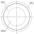
Fig. 3 is a top view of the splash guard of the present invention.
Fig. 4 is a cross-sectional view of the splash guard of the present invention.
Reference numerals: the bearing comprises a bearing box-1, a lifting eye screw-101, an air vent-102, an oil lubrication oil filling hole-103, a pump shaft-2, a bearing front gland-3, a grease lubrication oil filling hole-301, a bearing rear gland-4, a bearing-5, an anti-splash baffle-6, a bearing outer ring pressure plate-601, a support sleeve-602, an oil baffle-603, a shaft hole-6031, a straight-through pressure injection oil cup-7 and an oil ring sleeve-8.
Detailed Description
The utility model is described below with reference to the accompanying drawings and examples.
As shown in the accompanying drawings, a thin oil lubrication bearing body structure includes a bearing housing 1, a pump shaft 2, a bearing front gland 3, a bearing rear gland 4, a bearing 5 and an oil ring sleeve 8, wherein the bearing 5 adopts a rolling bearing, the bearing front gland 3 and the bearing rear gland 4 both adopt a through-cover structure with a through hole in the middle, the through-cover structure includes a disc and a cylinder, the disc and the cylinder are coaxially arranged, the end portion of the cylinder of the bearing front gland 3 is abutted against the front end face of a bearing outer ring, the end portion of the cylinder of the bearing rear gland 4 is abutted against the rear end face of the bearing outer ring, the bearing front gland 3 and the bearing rear gland 4 are respectively fixedly connected with the bearing housing 1 through bolts, the cylinder inner hole at the front end of the bearing rear gland 4 is set as a taper inner hole, oil return is facilitated, and the structures of the bearing front gland 3 and the bearing rear gland 4 are the prior art, and detailed description is omitted here.
The pump shaft 2 is connected with the bearing box body 1 through the bearing 5 and penetrates through the bearing front gland 3 and the bearing rear gland 4, the space between the bearing front gland 3 and the pump shaft 2 and the space between the bearing rear gland 4 and the pump shaft 2 are sealed, the rear end of the bearing 5 on the pump shaft 2 is also fixedly sleeved with the oil ring sleeve 8, the oil ring sleeve 8 is sleeved with the oil slinger, the oil ring sleeve 8 is driven to rotate through the rotation of the pump shaft 2, and the oil slinger is driven by the oil ring sleeve to rotate so as to bring lubricating oil into the bearing.
The upper end of the bearing box body 1 is provided with an air vent 102 communicated with the inside of the bearing box body 1, the lower end of the bearing box body is provided with a liquid drainage hole communicated with the inside of the bearing box body 1, the side surface of the bearing box body is provided with an oil lubrication oil filling hole 103 and an oil cup, and the top end of the bearing box body 1 is in threaded connection with a lifting bolt 101.
The bearing body structure is designed to realize that the bearing is lubricated by thin oil.
A splash-proof baffle 6 is added on the basis of the thin oil lubrication bearing body structure, the splash-proof baffle 6 comprises a bearing outer ring pressing plate 601 and a splash-proof sleeve, the shape of the bearing outer ring pressing plate 601 is matched with that of a bearing outer ring, the front end and the rear end of the splash-proof sleeve are arranged in a penetrating mode, the diameter of the front end opening of the splash-proof sleeve is larger than that of the rear end opening, and the front end of the splash-proof sleeve is fixedly connected with the inner end of the bearing outer ring pressing plate 601;
the anti-splashing sleeve is sleeved on the pump shaft 2 and positioned between the bearing 5 and the bearing rear gland 4, and the bearing outer ring pressing plate 601 is abutted against the bearing outer ring through the cylindrical end part of the bearing rear gland 4;
the grease lubrication oil filling hole 301 is formed in the bearing front gland 3, the grease lubrication oil filling hole 301 is communicated with the inside of the bearing box body 1, the splash-proof baffle plate 6 is arranged, the bearing outer ring pressing plate 601 is tightly pressed against the bearing outer ring through the bearing rear gland 4, the splash-proof sleeve can prevent lubricating grease from splashing, the thin oil lubrication bearing body is converted into the grease lubrication bearing body, original parts can be continuously used, the model does not need to be thrown again, the manufacturing cost is reduced, the material supply period is shortened, when the thin oil lubrication bearing body needs to be reused, the bearing rear gland 4 is detached, the splash-proof baffle plate 6 is taken out, and the grease lubrication bearing body can be converted into the thin oil lubrication bearing body.
The anti-splashing sleeve comprises a support sleeve 602 and an oil baffle 603, the front end of the support sleeve 602 is fixedly connected with the inner end of the bearing outer ring pressing plate 601, the rear end of the support sleeve is fixedly connected with the outer end of the oil baffle 603, a shaft hole 6031 through which a pump shaft can pass is formed in the middle of the oil baffle 603, and the oil baffle 603 is also of an annular structure in overall shape;
the anti-splash sleeve is sleeved on the pump shaft 2 through the shaft hole 6031 and the support sleeve 602, and the oil baffle 603 further ensures that the anti-splash effect is good.
The gland cylinder hole is the tapering hole behind the bearing, support the whole shape of cover 602 for with the bearing behind 4 tapering holes matched with frustum shape, the lateral wall of supporting cover 602 is laminated mutually with 4 tapering hole lateral walls of gland behind the bearing, further ensures that gland 4 can compress tightly splashproof baffle 6 behind the bearing.
The oil baffle 603 is sleeved on the oil ring sleeve 8 through a shaft hole 6031, the inner diameter of the shaft hole 6031 is larger than the outer diameter of the oil ring sleeve 8, so that the splashing of grease lubrication can be prevented, the oil ring sleeve 8 is prevented from interfering when the pump shaft 2 drives the oil ring sleeve 8 to rotate, and the splashing prevention baffle 6 can be taken out smoothly along the axial direction when grease lubrication conversion thin oil lubrication is ensured.
The grease lubrication oil filling hole 301 is composed of a radial oil filling hole and an axial oil filling hole, the radial oil filling hole is arranged along the radial direction of the bearing front gland 3 and penetrates through the outer side wall of the bearing front gland 3, the axial oil filling hole is arranged along the axial direction of the bearing front gland 3, one end of the axial oil filling hole is communicated with the radial oil filling hole, the other end of the axial oil filling hole is communicated with the inside of the bearing box body, so that maintenance personnel can be ensured to fill oil through the radial oil filling hole, and the oil filling is convenient.
The included angle between the radial oil filling hole and the horizontal line is 10-80 degrees, so that when lubricating grease is filled, other parts of the bearing box body cannot block the grease lubricating oil filling hole.
The grease lubrication oil filling device further comprises a straight-through type pressure filling oil cup 7, wherein an internal thread is arranged in the grease lubrication oil filling hole 301, an external thread is arranged on the straight-through type pressure filling oil cup 7, and the straight-through type pressure filling oil cup 7 is in threaded connection with the grease lubrication oil filling hole 301 so as to facilitate filling of lubricating grease. In this embodiment, the straight-through pressure-filling oil cup 7 is screwed to the radial filler hole.
In this embodiment, the bearing outer ring pressing plate 601, the supporting sleeve 602 and the oil baffle 603 are formed integrally.
When lubricating the bearing body structure with thin oil lubrication and grease rotation:
1. an operator unscrews the bolts on the bearing rear gland 4, detaches the bearing rear gland 4, takes off the oil slinger, sleeves the anti-splash baffle 6 on the pump shaft 2, fits the bearing outer ring pressing plate 601 with the rear end face of the bearing outer ring, and sleeves the oil baffle 603 outside the oil ring sleeve 8 through the shaft hole 6031;
2. sleeving a bearing rear gland 4 on the pump shaft 2, abutting the cylindrical end part of the bearing rear gland 4 on a bearing outer ring pressing plate 601, and fixing the bearing rear gland 4 and the bearing box body 1 through bolts;
3. the bearing 5 is filled with lubricating grease through the straight-through type pressure filling oil cup 7, and the anti-splashing baffle 6 is used for preventing the lubricating grease from splashing.
When grease lubrication changes thin oil lubrication bearing body structure:
1. an operator unscrews the bolts on the bearing rear gland 4, detaches the splash-proof baffle 6 from the pump shaft 2, sleeves the oil slinger on the oil ring sleeve 8, sleeves the bearing rear gland 4 on the pump shaft 2, and fixes the bearing rear gland 4 and the bearing box body 1 through the bolts;
2. the cover on the oil lubrication oil filling hole 103 is opened, lubricating oil is filled into the bearing box body 1, the pump shaft 2 is driven to rotate, the oil ring sleeve 8 is driven to rotate, the oil slinger is driven to rotate by the rotation of the oil ring sleeve 8, and the lubricating oil is brought into the bearing 5.
Claims (9)
1. The utility model provides a thin oil lubrication changes lubricated bearing body structure of fat, gland and bearing behind gland, the bearing before bearing box, pump shaft, bearing, its characterized in that: the anti-splash baffle comprises a bearing outer ring pressing plate and an anti-splash sleeve, wherein the shape of the bearing outer ring pressing plate is matched with that of the bearing outer ring, the front end and the rear end of the anti-splash sleeve are arranged in a penetrating mode, the diameter of the front end opening of the anti-splash sleeve is larger than that of the rear end opening, and the front end of the anti-splash sleeve is fixedly connected with the inner end of the bearing outer ring pressing plate;
the anti-splashing sleeve is sleeved on the pump shaft and positioned between the bearing and the bearing rear gland, and the bearing outer ring pressing plate is abutted against the bearing outer ring through the cylindrical end part of the bearing rear gland;
and the bearing front pressure cover is provided with a grease lubrication oil filling hole which is communicated with the inner part of the bearing box body.
2. The thin oil-lubricated grease-lubricated bearing body structure according to claim 1, wherein: the anti-splashing sleeve comprises a support sleeve and an oil baffle plate, the front end of the support sleeve is fixedly connected with the inner end of the bearing outer ring pressing plate, the rear end of the support sleeve is fixedly connected with the outer end of the oil baffle plate, a shaft hole through which the pump shaft can penetrate is formed in the middle of the oil baffle plate, and the anti-splashing sleeve is sleeved on the pump shaft through the shaft hole and the support sleeve.
3. The thin oil-lubricated grease-lubricated bearing body structure according to claim 2, wherein: the bearing rear gland cylinder inner hole is a taper inner hole, the whole shape of the support sleeve is a frustum shape matched with the bearing rear gland taper inner hole, and the outer side wall of the support sleeve is attached to the side wall of the bearing rear gland taper inner hole.
4. The thin oil-lubricated grease-lubricated bearing body structure according to claim 3, wherein: the bearing outer ring pressing plate, the supporting sleeve and the oil baffle plate are integrally formed.
5. The thin oil-lubricated grease-lubricated bearing body structure according to claim 2, 3 or 4, wherein: an oil ring sleeve is fixedly sleeved on the rear end of the bearing on the pump shaft.
6. The thin oil-lubricated grease-lubricated bearing body structure according to claim 5, wherein: the oil baffle plate is sleeved on the oil ring sleeve through a shaft hole, and the inner diameter of the shaft hole is larger than the outer diameter of the oil ring sleeve.
7. The thin oil-lubricated grease-lubricated bearing body structure according to claim 1, 2, 3, 4 or 6, wherein: the grease lubrication oil filling hole is composed of a radial oil filling hole and an axial oil filling hole, the radial oil filling hole is arranged along the radial direction of the bearing front gland and penetrates through the outer side wall of the bearing front gland, the axial oil filling hole is arranged along the axial direction of the bearing front gland, one end of the axial oil filling hole is communicated with the radial oil filling hole, and the other end of the axial oil filling hole is communicated with the inside of the bearing box body.
8. The bearing body structure for lubricating grease by thin oil according to claim 7, wherein: the included angle between the radial oil filling hole and the horizontal line is 10-80 degrees.
9. The thin oil-lubricated grease-lubricated bearing body structure according to claim 1, 2, 3, 4, 6 or 8, wherein: the grease lubrication oil filling device is characterized by further comprising a straight-through type pressure injection oil cup, wherein an internal thread is arranged in the grease lubrication oil filling hole, an external thread is arranged on the straight-through type pressure injection oil cup, and the straight-through type pressure injection oil cup is in threaded connection with the grease lubrication oil filling hole.
Priority Applications (1)
| Application Number | Priority Date | Filing Date | Title |
|---|---|---|---|
| CN202123357590.8U CN216642543U (en) | 2021-12-29 | 2021-12-29 | Lubricating bearing body structure for lubricating thin oil and rotating grease |
Applications Claiming Priority (1)
| Application Number | Priority Date | Filing Date | Title |
|---|---|---|---|
| CN202123357590.8U CN216642543U (en) | 2021-12-29 | 2021-12-29 | Lubricating bearing body structure for lubricating thin oil and rotating grease |
Publications (1)
| Publication Number | Publication Date |
|---|---|
| CN216642543U true CN216642543U (en) | 2022-05-31 |
Family
ID=81746494
Family Applications (1)
| Application Number | Title | Priority Date | Filing Date |
|---|---|---|---|
| CN202123357590.8U Active CN216642543U (en) | 2021-12-29 | 2021-12-29 | Lubricating bearing body structure for lubricating thin oil and rotating grease |
Country Status (1)
| Country | Link |
|---|---|
| CN (1) | CN216642543U (en) |
-
2021
- 2021-12-29 CN CN202123357590.8U patent/CN216642543U/en active Active
Similar Documents
| Publication | Publication Date | Title |
|---|---|---|
| CN206617584U (en) | A kind of sealing device of mortar vehicle agitating shaft shaft end | |
| US6058793A (en) | Parallel shaft speed reducer with sump and dry well | |
| CN216642543U (en) | Lubricating bearing body structure for lubricating thin oil and rotating grease | |
| CN204610558U (en) | A kind of two flange linear bearing assembly | |
| CN214196997U (en) | Self-balancing mechanical labyrinth sealed type thin oil lubrication bearing box | |
| CN115854006A (en) | Oil-water bidirectional sealing device for marine gearbox | |
| CN213451610U (en) | Spiral magnetic force combined sealing structure for end face sealing | |
| CN213145300U (en) | Oil leakage prevention radial sealing dry well device | |
| CN110821876B (en) | Bearing lubrication supercharging device of horizontal centrifugal pump | |
| CN201351732Y (en) | Oil sealing device for reduction gearbox bearing | |
| CN211398318U (en) | Bearing bush and gear box | |
| CN213393447U (en) | Oil leakage prevention speed reducer | |
| CN206530674U (en) | A kind of bearing pedestal supporting device for independently installed hydraulic machine | |
| CN205226370U (en) | Oil bath wheel hub | |
| CN218780651U (en) | Maintenance-free engine oil lubrication excitation assembly | |
| CN214221812U (en) | Self-lubricating bearing seat assembly structure of horizontal spiral sedimentation centrifuge | |
| CN215805811U (en) | Detachable oil injection bearing end cover | |
| CN219119500U (en) | Improved oil tank structure for large vertical pump | |
| CN220101782U (en) | Detachable gear shaft | |
| CN214036532U (en) | Bearing end cover assembly | |
| CN219452818U (en) | Novel box body assembly of power take-off transfer case of fire truck | |
| CN2193464Y (en) | Sealing end cap of bearing | |
| CN203307034U (en) | Lower rotating body of filling and can sealing unit | |
| CN112268103B (en) | Spiral magnetic force combined sealing structure for end face sealing | |
| CN206299791U (en) | Axle sealing device |
Legal Events
| Date | Code | Title | Description |
|---|---|---|---|
| GR01 | Patent grant | ||
| GR01 | Patent grant |