CN216639234U - Sludge pyrohydrolysis system with desanding function - Google Patents
Sludge pyrohydrolysis system with desanding function Download PDFInfo
- Publication number
- CN216639234U CN216639234U CN202122612392.5U CN202122612392U CN216639234U CN 216639234 U CN216639234 U CN 216639234U CN 202122612392 U CN202122612392 U CN 202122612392U CN 216639234 U CN216639234 U CN 216639234U
- Authority
- CN
- China
- Prior art keywords
- sand
- sludge
- tank
- desanding
- discharge port
- Prior art date
- Legal status (The legal status is an assumption and is not a legal conclusion. Google has not performed a legal analysis and makes no representation as to the accuracy of the status listed.)
- Active
Links
Images
Classifications
-
- Y—GENERAL TAGGING OF NEW TECHNOLOGICAL DEVELOPMENTS; GENERAL TAGGING OF CROSS-SECTIONAL TECHNOLOGIES SPANNING OVER SEVERAL SECTIONS OF THE IPC; TECHNICAL SUBJECTS COVERED BY FORMER USPC CROSS-REFERENCE ART COLLECTIONS [XRACs] AND DIGESTS
- Y02—TECHNOLOGIES OR APPLICATIONS FOR MITIGATION OR ADAPTATION AGAINST CLIMATE CHANGE
- Y02W—CLIMATE CHANGE MITIGATION TECHNOLOGIES RELATED TO WASTEWATER TREATMENT OR WASTE MANAGEMENT
- Y02W10/00—Technologies for wastewater treatment
- Y02W10/20—Sludge processing
Abstract
The utility model provides a sludge pyrohydrolysis system with a sand removing function, which comprises: the device comprises a slurry machine, a thermal hydrolysis reaction tank, a buffer grit tank, a heat exchanger and a cyclone desander; the first feeding pump conveys sludge treated by the slurrying machine to a thermal hydrolysis reaction tank, the second feeding pump conveys sludge subjected to thermal hydrolysis in the thermal hydrolysis reaction tank to a buffering grit tank for primary desanding, the third feeding pump conveys high-sand-content sludge treated by the buffering grit tank to a cyclone desander for secondary desanding, and heavier sand substances flow into a dehydration unit through a sand discharge port; and the fourth feeding pump conveys the desanding sludge treated by the buffering sand setting tank and the light sludge treated by the cyclone sand remover to the heat exchanger, and the waste heat of the sludge is cooled while being recovered by the heat exchanger and enters the anaerobic treatment unit. Buffering sand setting jar forms two-stage desanding system with the mutual cooperation of whirl desander, gets rid of the grit in the mud, avoids the grit in the mud to destroy anaerobic treatment equipment, improves anaerobic treatment's efficiency.
Description
Technical Field
The utility model relates to the technical field of sludge desanding, in particular to a sludge pyrohydrolysis system with a desanding function.
Background
Nowadays, anaerobic digestion is widely concerned in society because of the characteristics of sludge reduction, stabilization, harmlessness and recycling. The high-temperature pyrohydrolysis pretreatment technology for sludge is an efficient sludge pretreatment technology, can break the cell structure of sludge, accelerate the dissolution of macromolecular substances in the sludge, and overcome the wall breaking and dissolution rate-limiting factors of sludge microorganisms, thereby improving the hydrolysis rate of the sludge, improving the gas production rate of anaerobic digestion and shortening the sludge retention time.
However, the sludge often contains more inorganic granular components such as gravel due to different water quality of water plants, seasonal variation and the like, and the inorganic matter accounts for 50% or more. It deposits in the anaerobic digestion tank, on the one hand, causes equipment to be worn and on the other hand, influences anaerobic digestion process and efficiency. The removal of sand from the sludge is therefore critical to its subsequent disposal.
Disclosure of Invention
In order to solve the problems in the prior art, the utility model provides a sludge pyrohydrolysis system with a sand removing function.
The technical scheme of the utility model is as follows:
a sludge pyrohydrolysis system with sand removal function, comprising: the device comprises a pulp machine, a thermal hydrolysis reaction tank, a buffer grit chamber, a heat exchanger and a cyclone desander;
the slurrying machine is provided with a first feeding hole and a first discharging hole, the first feeding hole is connected with an external sludge source, and the first discharging hole is formed in the lower half part of the slurrying machine;
the thermal hydrolysis reaction tank is provided with a second feeding hole and a second discharging hole, the second feeding hole is connected with the first discharging hole through a first pipeline, a first conveying pump is arranged on the first pipeline, and the second discharging hole is formed in the bottom of the thermal hydrolysis reaction tank;
the buffer grit tank is provided with a third feeding hole, a desanding sludge discharging hole and a high sand-containing sludge discharging hole, the third feeding hole arranged at the top of the buffer grit tank is connected with the second discharging hole through a second pipeline, the high sand-containing sludge discharging hole is arranged at the bottom of the buffer grit tank, and the desanding sludge discharging hole is arranged in the middle of the buffer grit tank;
one end of the heat exchanger is connected with the desanding sludge discharge port through a fifth pipeline, the other end of the heat exchanger is connected with the anaerobic treatment unit, and a fourth feed pump is arranged on the fifth pipeline;
the cyclone desander is provided with a sludge inlet, a light sludge outlet and a sand discharge port, wherein the sludge inlet is connected with the high-sand sludge discharge port through a third pipeline, a third feeding pump is arranged on the third pipeline, the light sludge outlet is formed in the top of the cyclone desander, the light sludge outlet is connected with the feed end of the fourth feeding pump through a sixth pipeline, the sand discharge port is formed in the bottom of the cyclone desander, and the sand discharge port is connected with the dehydration unit through a fourth pipeline.
In the technical scheme, sludge enters a slurrying machine through a first feeding hole, a first conveying pump conveys the sludge treated by the slurrying machine to a pyrohydrolysis reaction tank, the pyrohydrolysis reaction tank carries out pyrohydrolysis treatment on the sludge in the reaction tank, a second feeding pump conveys the sludge subjected to heat treatment to a buffering sand setting tank through a second pipeline, the sludge subjected to pyrohydrolysis is temporarily stored in the buffering sand setting tank and then is separated into desanding sludge and high-sand-content sludge, the desanding sludge flows out through a desanding sludge outlet, a fourth feeding pump conveys the desanding sludge to a heat exchanger through a fifth pipeline, and the waste heat of the desanding sludge is cooled while being recovered through the heat exchanger and then enters an anaerobic treatment unit; high sand-containing sludge flows out through a high sand-containing sludge outlet, the third feeding pump conveys the high sand-containing sludge to a cyclone desander, the cyclone desander carries out secondary treatment on the high sand-containing sludge, heavier sand substances in the high sand-containing sludge flow out through a sand discharge port, the separated light sludge flows out through a light sludge outlet, the light sludge flows into a sixth pipeline, the fourth feeding pump conveys the light sludge in the sixth pipeline to a heat exchanger, the light sludge is cooled while the waste heat of the light sludge is recovered through the heat exchanger, and the light sludge enters an anaerobic treatment unit. Buffering grit chamber and whirl desander mutually support and form two-stage desanding system, get rid of the grit in the mud, avoid the grit in the mud to destroy the equipment in the anaerobic treatment, improve anaerobic treatment's efficiency.
On the basis of the scheme and as a preferable scheme of the scheme, a settling zone and a sand settling zone are arranged in the buffering sand setting tank, the settling zone is positioned above the sand settling zone, and a first stirring device is arranged on the buffering sand setting tank;
the first stirring device further comprises a first motor arranged on the buffering grit tank and a first stirring paddle arranged in the settling zone, and a first output shaft of the first motor is connected with a first rotating shaft of the first stirring paddle through a first coupler.
Among this technical scheme, start first motor, the first output shaft of first motor rotates, and first output shaft drives first rotation axis through first shaft coupling and rotates, and the rotation of first rotation axis makes first stirring thick liquid rotate for mud carries out primary separation, is the desanding mud in the settling area, through the outflow of desanding mud export, and the grit zone is high sand-containing mud, through the outflow of high sand-containing mud export.
On the basis of the scheme, and as a preferable scheme of the scheme, the volume ratio of the settling zone to the sand settling zone is 3:1-4: 1.
Among this technical scheme, the proportion setting in subsidence area and sand setting district is favorable to first stirring rake to stir, can improve the efficiency of sand setting simultaneously.
On the basis of the scheme, as a preferable scheme of the scheme, the length of the first stirring paddle in the grit zone is not more than 1/3 at the height in the grit zone, and the rotation speed of the first stirring paddle is 10-50 r/min.
In the technical scheme, the length of the first stirring paddle in the sand setting area is not more than 1/3 at the inner height of the sand setting area, so that the mud sand in the sand setting area can be prevented from being turned upwards on the basis of ensuring stirring.
On the basis of the scheme, as a preferable scheme of the scheme, a plurality of second stirring devices are arranged in the slurrying machine;
the second stirring device further comprises a second motor arranged on the pulp machine and a second stirring paddle arranged in the pulp machine, and a second output shaft of the second motor is in driving connection with a second rotating shaft on the second stirring paddle through a second coupling.
In this technical scheme, the pulp machine realizes the pulp through a plurality of second agitating unit, and second agitating unit theory of operation does, starts the second motor, and the second output shaft on the second motor rotates, and the second output shaft passes through second shaft coupling drive second rotation axis and rotates, and the second rotation axis rotates and drives second stirring rake and rotate, and then makes the pulp machine stir mud, and the first delivery pump of being convenient for extracts the transport.
On the basis of the scheme, and as a preferable scheme of the scheme, the manufacturing material of the cyclone desander is an abrasion-resistant material.
In the technical scheme, the cyclone desander is subjected to long-time sand washing in the actual use process, and the service life of the cyclone desander can be prolonged by the cyclone desander made of wear-resistant materials.
Compared with the prior art, the utility model has the following beneficial effects:
the utility model has simple structure, and the sand in the sludge can be effectively removed on the premise of lower organic matter loss; the sludge is firstly subjected to thermal hydrolysis treatment in the thermal hydrolysis reaction tank, the viscosity of the sludge can be reduced through the thermal hydrolysis treatment, wrapping adhesion of organic matters to gravel is reduced and removed, the fluidity of the sludge is improved, the sand removing efficiency is improved, the anaerobic digestion performance is improved, and the methane yield is increased.
Buffering sand setting jar and cyclone sand remover cooperate and form two-stage desanding system, at first the buffering sand setting jar carries out the one-level sand removal, then carry the cyclone sand remover through the third feeding pump with the high sand-containing mud of buffering sand setting jar and carry out the second grade sand removal, the cyclone sand remover has reduced the interference of organic matter to the cyclone sand removal, has improved the utilization ratio of cyclone sand remover, has improved the desanding efficiency of cyclone sand remover, prevents that the sand in the mud from deposiing in follow-up technology section, caking.
Drawings
Other features, objects and advantages of the utility model will become more apparent upon reading of the detailed description of non-limiting embodiments with reference to the following drawings:
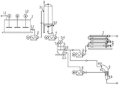
fig. 1 is a schematic view of the overall structure of the present invention.
In the figure: 1. a pulp machine; 1.1, a first feed inlet; 1.2, a first discharge hole; 1.3, a second stirring device; 2. A first feed pump; 3. a thermal hydrolysis reaction tank; 3.1, a second feed inlet; 3.2, a second discharge hole; 4. a second feed pump; 5. buffering the sand settling tank; 5.1, a third feeding port; 5.2, a sand-removed sludge discharge port; 5.3, a high sand-containing sludge discharge port; 5.4, a first stirring device; 6. a fourth feed pump; 7. a heat exchanger; 8. a third feed pump; 9. a cyclone desander; 9.1, a sludge inlet; 9.2, a light sludge outlet; 9.3, a sand discharge port.
Detailed Description
The present invention will be described in detail with reference to specific examples. The following examples will assist those skilled in the art in further understanding the utility model, but are not intended to limit the utility model in any way. It should be noted that it would be obvious to those skilled in the art that various changes and modifications can be made without departing from the spirit of the utility model. All falling within the scope of the present invention.
For better illustration of the utility model, the utility model is described in detail below with reference to fig. 1.
Referring to fig. 1, a sludge pyrohydrolysis system having a sand removing function includes: the system comprises a pulp machine 1, a thermal hydrolysis reaction tank 3, a buffer grit chamber 5, a heat exchanger 7 and a cyclone desander 9; the slurrying machine 1 is provided with a first feeding hole 1.1 and a first discharging hole 1.2, the first feeding hole 1.1 is connected with an external sludge source, and the first discharging hole 1.2 is arranged at the lower half part of the slurrying machine 1; the pyrohydrolysis reaction tank 3 is provided with a second feeding hole 3.1 and a second discharging hole 3.2, the second feeding hole 1.1 is connected with the first discharging hole 1.2 through a first pipeline, a first conveying pump is arranged on the first pipeline, and the second discharging hole 1.2 is arranged at the bottom of the pyrohydrolysis reaction tank 3; the sand setting tank is provided with a third feed port 5.1, a desanding sludge discharge port 5.2 and a high sand-containing sludge discharge port 5.3, the third feed port 5.1 arranged at the top of the sand setting tank is connected with a second discharge port 3.2 through a second pipeline, the high sand-containing sludge discharge port 5.3 is arranged at the bottom of the sand setting tank, and the desanding sludge discharge port 5.2 is arranged at the middle part of the sand setting tank; one end of the heat exchanger 7 is connected with a desanding sludge discharge port 5.2 through a fifth pipeline, the other end of the heat exchanger is connected with an anaerobic treatment unit, and a fourth feeding pump 6 is arranged on the fifth pipeline. A sludge inlet 9.1, a light sludge outlet 9.2 and a sand discharge port 9.3 are arranged on the cyclone desander 9, the sludge inlet 9.1 is connected with a high-sand sludge discharge port 5.3 through a third pipeline, a third feeding pump 8 is arranged on the third pipeline, the light sludge outlet 9.2 is arranged at the top of the cyclone desander 9, and the light sludge outlet 9.2 is connected with a feed end of a fourth feeding pump 6 through a sixth pipeline; the sand discharge port 9.3 is arranged at the bottom of the cyclone desander 9, and the sand discharge port 9.3 is connected with the dehydration unit through a fourth pipeline. It should be noted that the rotational flow desander 9 is made of wear-resistant material; the cyclone desander 9 is washed away by sand grains for a long time in the actual use process, and the service life of the cyclone desander 9 can be prolonged by the cyclone desander 9 made of wear-resistant materials. Specifically, the fourth feeding pump in this embodiment is a screw pump.
The method comprises the following steps that sludge enters a slurrying machine 1 through a first feeding hole 1.1, a first conveying pump conveys the sludge treated by the slurrying machine 1 to a pyrohydrolysis reaction tank 3, the pyrohydrolysis reaction tank 3 carries out pyrohydrolysis treatment on the sludge in the reaction tank, a second feeding pump 4 conveys the sludge subjected to thermal treatment to a sand setting tank through a second pipeline, the sludge subjected to pyrohydrolysis is temporarily stored in the sand setting tank and then is separated into desanding sludge and high sand-content sludge, the desanding sludge flows out through a desanding sludge outlet, a fourth feeding pump 6 conveys the desanding sludge to a heat exchanger 7 through a fifth pipeline, and the waste heat of the desanding sludge is cooled while being recovered through the heat exchanger 7 and then enters an anaerobic treatment unit; high sand-containing sludge flows out through a high sand-containing sludge outlet, the third feeding pump 8 conveys the high sand-containing sludge to the cyclone desander 9, the cyclone desander 9 carries out secondary treatment on the high sand-containing sludge, the heavier sand-like substances in the high sand-containing sludge flow out through the sand discharge port 9.3, the cyclone desander discharges the separated light sludge through the light sludge outlet 9.2, the light sludge flows into the sixth pipeline, the fourth feeding pump 6 conveys the light sludge in the sixth pipeline to the heat exchanger 7, the light sludge waste heat is cooled while being recovered through the heat exchanger 7, and the light sludge waste heat enters the anaerobic treatment unit. The method is characterized in that first-stage mud-sand separation is carried out in a buffering grit tank 5, high-sand-content sludge is conveyed into a cyclone desander 9 by a third feeding pump 8, the high-sand-content sludge rotationally flows in the cyclone desander 9, sand grains with high density are thrown to the wall of the cyclone desander 9 under the action of centrifugal force, fall into the conical part of the cyclone desander 9 along the inner wall of the cyclone desander 9 under the action of gravity until the sand outlet 9.3 at the lowest end of a cone is discharged, light sludge with the sand grains removed from the high-sand-content sludge is near the bottom of the cone, the light sludge is in ascending rotational motion, and finally flows out from the light sludge outlet 9.2 at the top end of equipment, and sand grains and sludge are separated.
The pyrohydrolysis reaction tank 3 firstly carries out pyrohydrolysis treatment on the sludge to reduce the viscosity of the sludge, reduce and remove wrapping adhesion of organic matters to gravel, improve the fluidity of the sludge, improve the desanding efficiency and anaerobic digestion performance and increase the yield of methane; buffering sand setting tank 5 and cyclone desander 9 cooperate and form two-stage desanding system, at first buffer sand setting tank 5 carries out the one-level sand removal, then carries cyclone desander 9 through third feeding pump 8 with the high sand-containing mud of buffering sand setting tank 5 and carries out the second grade sand removal, has reduced the interference of organic matter to the desanding, has improved desanding efficiency, prevents that the sand in the mud from deposiing, caking in follow-up technology section.
Referring to fig. 1, in the specific example of the present embodiment, a plurality of second stirring devices 1.3 are disposed in the slurry machine 1; the second stirring device 1.3 further comprises a second motor installed on the slurry machine 1 and a second stirring paddle arranged in the slurry machine 1, and a second output shaft of the second motor is in driving connection with a second rotating shaft on the second stirring paddle through a second coupling. The pulpifying machine 1 realizes the pulpifying through a plurality of second agitating units 1.3, and second agitating unit 1.3 theory of operation does, starts the second motor, and the second output shaft on the second motor rotates, and the second output shaft passes through second shaft coupling drive second rotation axis and rotates, and the second rotation axis rotates and drives second stirring rake and rotate, and then makes pulpifying machine 1 stir mud, and the first charge pump 2 of being convenient for extracts the transport.
In a specific example of this embodiment, a settling zone and a grit zone are arranged in the grit tank, the settling zone is located above the grit zone, and the grit tank is provided with a first stirring device 5.4; the first stirring device 5.4 further comprises a first motor arranged on the sand settling tank and a first stirring paddle arranged in the settling zone, and a first output shaft of the first motor is connected with a first rotating shaft of the first stirring paddle through a first coupler. It is noted that the volume ratio of the settling zone to the sand settling zone is 3:1 to 4: 1. The proportion setting in subsidence area and sand setting district is favorable to first stirring rake to stir, can improve the efficiency of sand setting simultaneously. It is worth mentioning that the length of the first stirring paddle in the sand setting zone is not more than 1/3 located at the height of the sand setting zone, and the rotation speed of the first stirring paddle is 10 to 50 r/min. The length of the first stirring paddle in the sand setting area is no more than 1/3 at the height in the sand setting area, so that the mud sand in the sand setting area can be placed to be turned upwards on the basis of ensuring stirring.
In actual use, start first motor, the first output shaft of first motor rotates, and the rotation rate is 25r/min, and first output shaft drives first rotation axis through first shaft coupling and rotates, and the rotation of first rotation axis makes first stirring thick liquid rotate for mud carries out primary separation, for the desanding sludge in the settling zone, through the outflow of desanding sludge outlet, the grit zone is high sand-containing mud, through the outflow of high sand-containing sludge outlet.
In the using process of the utility model, sludge enters the slurrying machine 1 through the first feeding hole 1.1, the second motor on the slurrying machine 1 is started, the second output shaft on the second motor rotates, the second output shaft drives the second rotating shaft to rotate through the second coupler, the second rotating shaft rotates to drive the second stirring paddle to rotate, so that the slurrying machine 1 can stir the sludge, the sludge treated by the slurrying machine 1 is conveyed to the pyrohydrolysis reaction tank 3 through the first conveying pump, the pyrohydrolysis reaction tank 3 can carry out pyrohydrolysis treatment on the sludge in the reaction tank, the second feeding pump 4 can convey the thermally treated sludge to the sand setting tank through the second pipeline, the thermally hydrolyzed sludge is temporarily stored in the sand setting tank and then separated into desanding sludge and high sand-content sludge, the desanding sludge flows out through the desanding sludge outlet, the fourth feeding pump 6 can convey the desanding sludge to the heat exchanger 7 through the fifth pipeline, the waste heat of the desanding sludge is cooled while being recovered by the heat exchanger 7, and then enters an anaerobic treatment process; high sand-containing sludge flows out through a high sand-containing sludge outlet, the third feeding pump 8 conveys the high sand-containing sludge to a cyclone desander 9, the cyclone desander 9 carries out cyclone desanding, and heavier sand substances flow out through a sand discharge port 9.3 and then flow into a dehydration unit for treatment; the cyclone separator enables the separated light sludge to flow out through a light sludge outlet 9.2, the light sludge flows into a sixth pipeline, a fourth feeding pump 6 conveys the light sludge in the sixth pipeline into a heat exchanger 7, the light sludge is cooled while the waste heat of the light sludge is recovered through the heat exchanger 7, and the light sludge enters an anaerobic treatment unit. The buffering sand setting tank 5 and the cyclone sand remover 9 are matched to form a two-stage sand removing system, the buffering sand setting tank 5 is firstly subjected to primary sand removal, then the high-sand-content sludge of the buffering sand setting tank 5 is conveyed to the cyclone sand remover 9 through the third feeding pump 8 to be subjected to secondary sand removal, the interference of organic matters to cyclone sand removal is reduced, the sand removing efficiency is improved, and the sand in the sludge is prevented from being deposited and agglomerated in a subsequent process section.
The foregoing description of specific embodiments of the present invention has been presented. It is to be understood that the present invention is not limited to the specific embodiments described above, and that various changes, modifications, or combinations may be made by those skilled in the art within the scope of the claims without departing from the spirit of the utility model. The embodiments and features of the embodiments of the present application may be combined with each other arbitrarily without conflict.
Claims (6)
1. A sludge pyrohydrolysis system with a desanding function is characterized by comprising: the device comprises a pulp machine, a thermal hydrolysis reaction tank, a buffer grit chamber, a heat exchanger and a cyclone desander;
the slurrying machine is provided with a first feeding hole and a first discharging hole, the first feeding hole is connected with an external sludge source, and the first discharging hole is formed in the lower half part of the slurrying machine;
the thermal hydrolysis reaction tank is provided with a second feeding hole and a second discharging hole, the second feeding hole is connected with the first discharging hole through a first pipeline, a first conveying pump is arranged on the first pipeline, and the second discharging hole is formed in the bottom of the thermal hydrolysis reaction tank;
the buffer grit tank is provided with a third feed port, a desanding sludge discharge port and a high-sand-content sludge discharge port, the third feed port arranged at the top of the buffer grit tank is connected with the second discharge port through a second pipeline, the high-sand-content sludge discharge port is arranged at the bottom of the buffer grit tank, and the desanding sludge discharge port is arranged in the middle of the buffer grit tank;
one end of the heat exchanger is connected with the desanding sludge discharge port through a fifth pipeline, the other end of the heat exchanger is connected with the anaerobic treatment unit, and a fourth feeding pump is arranged on the fifth pipeline;
the cyclone desander is provided with a sludge inlet, a light sludge outlet and a sand discharge port, wherein the sludge inlet is connected with the high-sand sludge discharge port through a third pipeline, a third feeding pump is arranged on the third pipeline, the light sludge outlet is formed in the top of the cyclone desander, the light sludge outlet is connected with the feed end of the fourth feeding pump through a sixth pipeline, the sand discharge port is formed in the bottom of the cyclone desander, and the sand discharge port is connected with the dehydration unit through a fourth pipeline.
2. The sludge pyrohydrolysis system with sand removing function as claimed in claim 1, wherein a settling zone and a sand settling zone are arranged in the buffering sand settling tank, the settling zone is located above the sand settling zone, and a first stirring device is arranged on the buffering sand settling tank;
the first stirring device further comprises a first motor arranged on the buffering grit tank and a first stirring paddle arranged in the settling zone, and a first output shaft of the first motor is connected with a first rotating shaft of the first stirring paddle through a first coupler.
3. The sludge pyrohydrolysis system with sand removing function as claimed in claim 2, wherein the volume ratio of the settling zone to the sand settling zone is 3:1-4: 1.
4. The sludge pyrohydrolysis system with sand removing function as claimed in claim 2 or 3, wherein the length of the first stirring blade in the sand setting zone is not more than 1/3 at the height of the sand setting zone, and the rotation speed of the first stirring blade is 10-50 r/min.
5. The sludge pyrohydrolysis system with sand removing function as claimed in claim 1, wherein a plurality of second stirring devices are arranged in the slurry machine;
the second stirring device further comprises a second motor arranged on the pulp machine and a second stirring paddle arranged in the pulp machine, and a second output shaft of the second motor is in driving connection with a second rotating shaft on the second stirring device through a second coupling.
6. The sludge pyrohydrolysis system with sand removing function as claimed in claim 1, wherein the cyclone sand remover is made of wear-resistant material.
Priority Applications (1)
| Application Number | Priority Date | Filing Date | Title |
|---|---|---|---|
| CN202122612392.5U CN216639234U (en) | 2021-10-28 | 2021-10-28 | Sludge pyrohydrolysis system with desanding function |
Applications Claiming Priority (1)
| Application Number | Priority Date | Filing Date | Title |
|---|---|---|---|
| CN202122612392.5U CN216639234U (en) | 2021-10-28 | 2021-10-28 | Sludge pyrohydrolysis system with desanding function |
Publications (1)
| Publication Number | Publication Date |
|---|---|
| CN216639234U true CN216639234U (en) | 2022-05-31 |
Family
ID=81734568
Family Applications (1)
| Application Number | Title | Priority Date | Filing Date |
|---|---|---|---|
| CN202122612392.5U Active CN216639234U (en) | 2021-10-28 | 2021-10-28 | Sludge pyrohydrolysis system with desanding function |
Country Status (1)
| Country | Link |
|---|---|
| CN (1) | CN216639234U (en) |
-
2021
- 2021-10-28 CN CN202122612392.5U patent/CN216639234U/en active Active
Similar Documents
| Publication | Publication Date | Title |
|---|---|---|
| CN114260106B (en) | Classification treatment system for earth pressure balance shield dregs | |
| CN106269797B (en) | Kitchen garbage level four is selected separately edulcoration system | |
| CN211005048U (en) | Sludge recovery device for paper mill | |
| CN202845157U (en) | Drum separation equipment for disposing kitchen waste | |
| CN207630582U (en) | A kind of kitchen garbage waterpower wash engine | |
| CN202729965U (en) | Oil field skid-mounted type oil field waste treatment device | |
| CN201791598U (en) | Spirally discharging sedimentation centrifuge for bentonite | |
| CN216639234U (en) | Sludge pyrohydrolysis system with desanding function | |
| CN102974450B (en) | Rotary drum separating system for processing kitchen waste | |
| CN103817019A (en) | Novel horizontal spiral decanting centrifuge | |
| CN104232690A (en) | Treatment method of kitchen waste | |
| CN218188076U (en) | Sand washing wastewater gravity concentration deposition prevention device | |
| CN215995736U (en) | Double-inlet multi-cone belt kitchen and kitchen waste desanding equipment | |
| CN103433271B (en) | The grease simultaneously device of separating heavy pledge and separation method is extracted from changing food waste | |
| CN103406212A (en) | Small super-speed horizontal helical centrifugal machine | |
| CN216909505U (en) | Combined type solid-liquid separation and filtration equipment for mine | |
| CN106986357B (en) | A kind of pyrosulfurous acid mother liquid of sodium reclaiming system | |
| CN211885783U (en) | Bucket lifting type fine sand recovery equipment | |
| CN211885784U (en) | Mortar pump type fine sand recovery equipment | |
| CN204486450U (en) | A kind of organic anaerobic ferment devices | |
| CN205701072U (en) | Domestic garbage compression-classification dual treatment organic matter pulp thickener | |
| CN209810111U (en) | Oily sludge granulation equipment | |
| CN203711163U (en) | Novel horizontal decanter centrifuge | |
| CN108067358B (en) | Oil-water-sand separation three-phase horizontal spiral centrifuge | |
| CN214415681U (en) | Novel sand-water separator |
Legal Events
| Date | Code | Title | Description |
|---|---|---|---|
| GR01 | Patent grant | ||
| GR01 | Patent grant |