CN216620058U - Air conditioner - Google Patents
Air conditioner Download PDFInfo
- Publication number
- CN216620058U CN216620058U CN202122404400.7U CN202122404400U CN216620058U CN 216620058 U CN216620058 U CN 216620058U CN 202122404400 U CN202122404400 U CN 202122404400U CN 216620058 U CN216620058 U CN 216620058U
- Authority
- CN
- China
- Prior art keywords
- wall
- air
- fan
- chamber
- air conditioner
- Prior art date
- Legal status (The legal status is an assumption and is not a legal conclusion. Google has not performed a legal analysis and makes no representation as to the accuracy of the status listed.)
- Active
Links
- 238000001704 evaporation Methods 0.000 claims abstract description 57
- 230000008020 evaporation Effects 0.000 claims abstract description 54
- 238000009833 condensation Methods 0.000 claims abstract description 38
- 230000005494 condensation Effects 0.000 claims abstract description 38
- 238000005192 partition Methods 0.000 claims description 51
- 239000002184 metal Substances 0.000 claims description 11
- 229910052751 metal Inorganic materials 0.000 claims description 11
- 230000009467 reduction Effects 0.000 claims description 9
- 238000005265 energy consumption Methods 0.000 abstract description 4
- 239000003507 refrigerant Substances 0.000 description 44
- 239000003990 capacitor Substances 0.000 description 14
- 238000012423 maintenance Methods 0.000 description 8
- 238000009434 installation Methods 0.000 description 6
- XLYOFNOQVPJJNP-UHFFFAOYSA-N water Substances O XLYOFNOQVPJJNP-UHFFFAOYSA-N 0.000 description 6
- 230000002349 favourable effect Effects 0.000 description 5
- 238000000034 method Methods 0.000 description 5
- 230000000694 effects Effects 0.000 description 4
- 238000005452 bending Methods 0.000 description 3
- RYGMFSIKBFXOCR-UHFFFAOYSA-N Copper Chemical compound [Cu] RYGMFSIKBFXOCR-UHFFFAOYSA-N 0.000 description 2
- 230000009471 action Effects 0.000 description 2
- 229910052802 copper Inorganic materials 0.000 description 2
- 239000010949 copper Substances 0.000 description 2
- 238000001035 drying Methods 0.000 description 2
- 230000017525 heat dissipation Effects 0.000 description 2
- 239000012535 impurity Substances 0.000 description 2
- 238000012986 modification Methods 0.000 description 2
- 230000004048 modification Effects 0.000 description 2
- 230000008569 process Effects 0.000 description 2
- 238000005057 refrigeration Methods 0.000 description 2
- 238000007789 sealing Methods 0.000 description 2
- 239000000243 solution Substances 0.000 description 2
- 238000012546 transfer Methods 0.000 description 2
- 238000013024 troubleshooting Methods 0.000 description 2
- 230000004888 barrier function Effects 0.000 description 1
- 230000009286 beneficial effect Effects 0.000 description 1
- 238000004891 communication Methods 0.000 description 1
- 238000001816 cooling Methods 0.000 description 1
- 238000002347 injection Methods 0.000 description 1
- 239000007924 injection Substances 0.000 description 1
- 238000011835 investigation Methods 0.000 description 1
- 230000002093 peripheral effect Effects 0.000 description 1
- 238000001556 precipitation Methods 0.000 description 1
- 230000002035 prolonged effect Effects 0.000 description 1
- 210000004722 stifle Anatomy 0.000 description 1
- 238000006467 substitution reaction Methods 0.000 description 1
- 238000009423 ventilation Methods 0.000 description 1
- 238000003466 welding Methods 0.000 description 1
Images


Abstract
The application relates to an air conditioner, which comprises a shell, a compressor, a condenser, a condensation side fan, an evaporator and an evaporation side fan. The housing has a first chamber and a second chamber spaced apart from each other, the compressor, the condenser, and the condensing side fan are disposed in the first chamber, and the evaporator and the evaporating side fan are disposed in the second chamber. The evaporator is provided with an air inlet side and an air outlet side, the evaporation side fan comprises a second motor, a second impeller driven by the second motor and a second casing accommodating the second impeller, and the second casing is provided with an air inlet facing the air outlet side of the evaporator. The evaporation side fan reduces wind resistance, ensures air quantity and reduces energy consumption.
Description
Technical Field
The application relates to the field of air conditioners, in particular to an air conditioner for kitchen.
Background
The kitchen air conditioner is mainly applied to the kitchen environment in summer, and the pain of cookers caused by high-temperature sultriness of the kitchen in summer is solved. Because the existing kitchen generally lacks a space for placing the outdoor unit, the air conditioner is usually made into an integrated structure, and the whole machine is installed in a suspended ceiling of the kitchen. Because the height of the common kitchen ceiling is relatively short, the selection of the compressor is limited to a certain extent, the refrigerating capacity of the system is ensured, and meanwhile, the installation thickness requirement of the whole machine is met. In the related art, the placement position of the fan is random, and the fan is difficult to be well matched with the air outlet direction of the evaporator, so that the problems of large wind resistance, high energy consumption and the like are caused.
SUMMERY OF THE UTILITY MODEL
An object of the present application is to provide an air conditioner to solve the above technical problems.
In order to achieve the purpose, the following technical scheme is adopted in the application:
the utility model provides an air conditioner, includes casing, compressor, condenser, condensation side fan, evaporimeter and evaporation side fan, the casing has first cavity and the second cavity that separates each other, the compressor the condenser with condensation side fan set up in the first cavity, the evaporimeter with evaporation side fan set up in the second cavity, the evaporimeter has air inlet side and air-out side, evaporation side fan include the second motor drive's second impeller and accept the second casing of second impeller, the second casing have towards the air intake of evaporimeter air-out side.
Compared with the related art, the method has the advantages that: because the air inlet of this application evaporation side fan is towards the air-out side of evaporimeter, be favorable to the air directly to be inhaled by evaporation side fan behind the evaporimeter for the evaporation side fan of this application has reduced the windage, has both ensured the amount of wind and has reduced the energy consumption.
Drawings
Fig. 1 is a schematic view of the overall structure of the air conditioner of the present application;
FIG. 2 is a schematic view of the overall structure of the air conditioner according to another aspect of the present application;
FIG. 3 is a schematic view of the overall structure of the air conditioner according to the present application from a further angle;
FIG. 4 is a schematic view of the overall structure of the air conditioner according to the present application from yet another angle;
FIG. 5 is a top view of FIG. 1;
FIG. 6 is a side view of FIG. 1;
FIG. 7 is an exploded perspective view of the first access panel and the second access panel of FIG. 1 taken apart from the machine;
FIG. 8 is a further exploded perspective view of FIG. 7;
FIG. 9 is an exploded perspective view of the third access panel of FIG. 3 removed from the machine;
FIG. 10 is an exploded perspective view of the compressor and housing shown separated from other components of the air conditioner of the present application;
FIG. 11 is an exploded perspective view of the evaporator side fan and bracket of the present application air conditioner, shown separated from other components of the present application air conditioner;
fig. 12 is a perspective combination view of an evaporation side fan in the air conditioner of the present application;
FIG. 13 is an enlarged view of a portion of FIG. 7;
fig. 14 is a partially enlarged view of fig. 10.
Detailed Description
Exemplary embodiments of the present application will be described in detail below with reference to the accompanying drawings. If several embodiments exist, the features of these embodiments may be combined with each other without conflict. When the description refers to the accompanying drawings, like numbers in different drawings represent the same or similar elements unless otherwise indicated. The description set forth below in the exemplary detailed description does not represent all embodiments consistent with the present application; rather, they are merely examples of apparatus, products, and/or methods consistent with certain aspects of the present application, as recited in the claims of the present application.
The terminology used in the present application is for the purpose of describing particular embodiments only and is not intended to limit the scope of the present application. As used in the specification and claims of this application, the singular form of "a", "an", or "the" is intended to include the plural forms as well, unless the context clearly indicates otherwise.
It should be understood that the terms "first," "second," and the like, as used in the description and claims of this application, do not denote any order, quantity, or importance, but rather are used to distinguish one feature from another. Also, the use of the terms "a" or "an" and the like do not denote a limitation of quantity, but rather denote the presence of at least one. Unless otherwise indicated, the terms "front," "back," "up," "down," and the like in this application are used for convenience of description, and are not limited to a particular position or spatial orientation. The word "comprising" or "comprises", and the like, is intended to be open-ended, meaning that an element that appears before "comprises" or "comprising" includes "or" includes "and its equivalents, that do not exclude the presence of other elements in addition to the element that appears before" comprising "or" including ". In this application, the meaning of "a number" if it occurs is two as well as more than two.
The household air conditioner mostly adopts a split structure of an indoor unit and an outdoor unit, but some high-rise residences at present do not have corresponding installation platforms arranged outside a kitchen, so that the outdoor unit of the air conditioner cannot be installed in the kitchen.
The application provides an air conditioner, the air conditioner does not have the off-premises station, therefore need not occupy extra outdoor platform, makes the air conditioner can the complete machine be installed in the space more than the kitchen furred ceiling, can cool down the kitchen room temperature in summer to improve the sense of discomfort because of high temperature stifle brings for the human body. It will be readily appreciated that the air conditioner may be applied to other environments besides a kitchen. And are not limited herein.
The application discloses an air conditioner 100, which comprises a shell 1, and a compressor 2, a condenser 31, a throttling element 521, an evaporator 32, a condensation side fan 41, an evaporation side fan 42, a pipeline 5 and an electric control unit 8 which are arranged in the shell 1. At least one of the space between the compressor 2 and the condenser 31, the space between the condenser 31 and the throttling element 521, and the space between the evaporator 32 and the compressor 2 is connected by a section of the pipeline 5, and in the embodiments provided in the present application, a section of the pipeline 5 is provided between the compressor 2 and the condenser 31, between the condenser 31 and the throttling element 521, and between the evaporator 32 and the compressor 2. The throttling element 521 can be integrated in the evaporator 32 or can be independent from the evaporator 32, and in the case that the throttling element 521 is independent from the evaporator 32, the throttling element 521 and the evaporator 32 are also connected through a section of the pipeline 5; the electronic control unit 8 is electrically connected to the compressor 2, the condenser-side fan 41, and the condenser-side fan 42, respectively.
Referring to fig. 1 to 5, the housing 1 includes a bottom wall 11 extending horizontally and a side wall 12 extending vertically upward from an edge of the bottom wall 11. The side wall 12 includes a first side wall 121, a second side wall 122, a third side wall 123, a fourth side wall 124, a fifth side wall 125 and a sixth side wall 126 connected end to end. In the present embodiment, since the bottom wall 11 is a rectangle including two long sides and two short sides (a square is a special rectangle, and a square bottom wall 11 with equal long sides and short sides is also covered by the present application), the third side wall 123 and the fourth side wall 124 are integrally formed on one long side of the bottom wall 11, the first side wall 121 and the sixth side wall 126 are integrally formed on the other long side of the bottom wall 11, and the second side wall 122 and the fifth side wall 125 are respectively located on two opposite short sides of the bottom wall 11. The housing 1 further includes a first partition 13 extending upward perpendicular to the bottom wall 11 and disposed in parallel between the second sidewall 122 and the fifth sidewall 125, one end of the first partition 13 is vertically disposed at a junction of the first sidewall 121 and the sixth sidewall 126, and the other end of the first partition 13 is vertically disposed at a junction of the fourth sidewall 124 and the third sidewall 123. It is to be emphasized that: the "connection part" herein includes two forms of "integral connection" and "split connection": that is, the first sidewall 121 and the sixth sidewall 126 may be integrally connected by the same plate, or may be separately connected by two plates. Similarly, the fourth sidewall 124 and the third sidewall 123 may be integrally connected by the same plate, or may be separately connected by two plates. "integrally connected" is an alternative embodiment of the present application. Thus, the first sidewall 121, the second sidewall 122, the third sidewall 123 and the first partition 13 enclose a first chamber 101 for circulating hot air. The first partition 13, the fourth side wall 124, the fifth side wall 125 and the sixth side wall 126 enclose a second chamber 102 for circulating the cold air. The first partition 13 separates the gas environments of the first chamber 101 and the second chamber 102, so as to ensure that the hot air in the first chamber 101 and the cold air in the second chamber 102 do not interfere with each other in the working state of the air conditioner 100.
As mentioned above, in the first embodiment of the present application, the first rectangular first chamber 101 and the second rectangular second chamber 102 are defined by the first side wall 121, the second side wall 122, the third side wall 123 and the first partition 13, and the second rectangular first chamber 101 is defined by the fourth side wall 124, the fifth side wall 125, the sixth side wall 126 and the first partition 13, that is, the above-mentioned "the third side wall 123 and the fourth side wall 124 are on one long side of the bottom wall 11, the first side wall 121 and the sixth side wall 126 are on the other long side of the bottom wall 11, and the second side wall 122 and the fifth side wall 125 are respectively located on two opposite short sides of the bottom wall 11", so that the first rectangular first chamber 101 and the second rectangular second chamber 102 constitute a large rectangular chamber.
In the second embodiment of the present application, even the parallel relationship between the oppositely disposed first sidewall 121 and third sidewall 123, the oppositely disposed second sidewall 122 and first partition 13, the oppositely disposed fourth sidewall 124 and sixth sidewall 126, and the oppositely disposed fifth sidewall 125 and first partition 13 is not necessary, and only a quadrilateral accommodating space is required to be enclosed, for example: the first side wall 121, the second side wall 122, the third side wall 123 and the first partition plate 13 together enclose a first chamber 101 forming a first isosceles trapezoid, the fourth side wall 124, the fifth side wall 125, the sixth side wall 126 and the first partition plate 13 together enclose a second chamber 102 forming a second isosceles trapezoid, and the first chamber 101 and the second chamber 102 of the two isosceles trapezoids share a lower bottom edge (i.e., the first partition plate 13) to form a large regular hexagon chamber.
The casing 1 also comprises a top wall, in the usual sense of an air conditioner (not shown), arranged opposite the bottom wall 11, which can substantially close the first chamber 101 and the second chamber 102. In other embodiments, the top wall may not be provided. For example: the air conditioner without the upper cover is snap-fitted upward to the roof of the kitchen, forming a closed chamber by means of the roof.
The compressor 2, the condenser 31, and the condenser-side fan 41 are housed in the first chamber 101. The evaporator 32 and the evaporation-side fan 42 are housed in the second chamber 102. The condenser 31 and the evaporator 32 are both heat exchangers, and both follow the working principle of the heat exchangers. In the present embodiment, the refrigerant in the condenser 31 and the refrigerant in the evaporator 32 exchange heat with air, but since the temperature of the refrigerant in the condenser 31 is different from the temperature of the refrigerant in the evaporator 32, the high-temperature refrigerant in the condenser 31 has an effect of raising the temperature of air, and the low-temperature refrigerant in the evaporator 32 has an effect of lowering the temperature of air.
As is well known, the compressor 2 has a discharge port. Referring to fig. 1 to 5, the compressor 2 includes a head portion 21 and a tail portion 22 opposite to the head portion 21. The head 21 and the tail 22 of the compressor 2 are arranged along the length direction of the compressor 2. The discharge port of the compressor 2 is closer to the head 21. The bottom of head 21 and the bottom of afterbody 22 all are provided with fixed bolster 23, are connected through elastic component 24 between fixed bolster 23 and the diapire 11, so make compressor 2 set up on diapire 11 elastically, and elastic component 24 can absorb the vibration that produces when partly compressor 2 starts to can the noise reduction. The compressor 2 is a horizontal compressor, in the length direction of the compressor 2, at least part of the condenser 31 is located on one side of the head 21 of the compressor 2 away from the tail 22, the tail 22 is closer to the condensing side fan 41 than the head 21, the tail 22 is provided with mechanical moving parts of the compressor 2, the mechanical moving parts include a cylinder, a stator, a rotor, a piston and the like, the stator and the rotor are basically located in the middle of the horizontal compressor, the cylinder and the piston are basically located in the tail 22 of the horizontal compressor, and the head 21 of the horizontal compressor is basically not provided with more moving parts, so that the noise source of the horizontal compressor is more concentrated on the latter half between the middle and the tail 22, the content of the part is the prior art in the field, and the description of the present application is omitted. And the working principle of the cylinder, the stator, the rotor and the piston inside the compressor 2 are well known in the art, and the detailed description is omitted here.
The condenser side fan 41 is fixedly provided on the inner wall surface of the first side wall 121, and in the present embodiment, the condenser 31 is bent in an L shape to be provided on the inner wall surface of the second side wall 122 and the inner wall surface of the third side wall 123 in order to meet the heat exchange requirement. In other embodiments, the condenser 31 may be disposed only on the inner wall surface of the second sidewall 122 or only on the inner wall surface of the third sidewall 123. Alternatively, the compressor 2 is disposed at a middle position of the first chamber 101, and a first direction in which the head portion 21 extends toward the tail portion 22 coincides with an extending direction of the first barrier 13. Alternatively, the length direction of the compressor 2, i.e., the first direction extending from the head portion 21 to the tail portion 22, is perpendicular to the axial direction of the first motor 411 in the condensation side fan 41, so as to facilitate the discharge of the hot air. The compressor 2 may be disposed in the first receiving chamber 101 at an inclination (for example, at an inclination of 45 degrees) as long as the tail portion 22 is closer to the condensing-side fan 41 than the head portion 21 and the head portion 21 is closer to the condenser 31 than the tail portion 22 is.
The second sidewall 122 and/or the third sidewall 123 are provided with a condensation side air inlet 1201, and the condenser 31 is fixedly arranged beside the condensation side air inlet 1201. The inside of the condenser 31 is provided with a refrigerant circulation channel, so that air outside the housing 1 and above the kitchen ceiling enters the first chamber 101 through the condensation side air inlet 1201, exchanges heat with the condenser 31 fixed at the position of the condensation side air inlet 1201, and hot air after heat exchange is discharged outside the first chamber 101 by the condensation side fan 41. In the actual installation, be equipped with the return air panel on the kitchen furred ceiling, the return air panel intercommunication on condensation side air inlet 1201 and the kitchen furred ceiling, then this application utilizes the indoor air of kitchen furred ceiling below as the air supply of kitchen furred ceiling top simultaneously, is favorable to improving the heat exchange efficiency of air conditioner.
The condenser 31 is provided with a pipe through which the refrigerant flows, and a passage through which air flows is formed around the pipe. The channel in the condenser 31 communicates with the first chamber 101, so that the air passing through the channel can exchange heat with the refrigerant in the duct through the wall of the duct. The condenser 31 is not necessarily limited to an L shape, and the L-shaped condenser 31 is only used for two condensation side air inlets 1201 to meet the requirement of increasing the heat exchange amount.
In particular embodiments, condenser 31 may be a multi-pass heat exchanger. For example, the heat exchanger can be a copper tube fin type heat exchanger, and can also be a micro-channel heat exchanger with flat tubes and collecting tubes. The use of the microchannel heat exchanger is advantageous in reducing the weight of the condenser 31 and reducing the size of the condenser 31. The flat tube is usually provided with a plurality of channels for the flow of refrigerant therein. And a channel for air circulation is formed between the flat pipe and the flat pipe. Adjacent passageway keeps apart each other, and a plurality of passageways are arranged into one row, influences the width of flat pipe jointly, and flat pipe is whole to be the platykurtic, and its length is greater than the width, and the width is greater than its thickness again. The length direction of the flat pipe is the flowing direction of the refrigerant determined by the channel in the flat pipe. The length direction of the flat pipe can be a straight line type, a broken line type, a bending type and the like. The flat tube is not limited to this type, and may have other shapes.
Referring to fig. 1, 3 and 4, the condensing side fan 41 includes a first casing 413, a first motor 411 and at least one first impeller (not shown). In this embodiment, there are two first impellers, the first motor 411 is disposed at a middle position between the two first impellers, and the first motor 411 drives the two first impellers to rotate coaxially. The condensing side fan 41 is a direct current fan, which has a large air volume and can rapidly discharge air in the first chamber 101. The pressure head of the direct current fan is high, so that the length of the exhaust pipe can be prolonged, and the air in the first cavity 101 is discharged to the outside. The casing height of direct current fan is below 200mm, can reduce the thickness of the complete machine of air conditioner 100, and the installation scene is abundanter various. The direct current fan noise is low, and the user experience is better.
The first side wall 121 is provided with at least one condensation side exhaust port 1203, and in the present embodiment, there are two condensation side exhaust ports 1203 corresponding to the two first impellers. The condensation side air outlet 1203 is equipped with condensation side fan 41 towards the inboard of first cavity 101, the air outlet and the condensation side air outlet 1203 of condensation side fan 41 are connected, the outside that condensation side air outlet 1203 is kept away from first cavity 101 is equipped with first wind gap connecting piece 1205, first wind gap connecting piece 1205 is connected with intercommunication condensation side air outlet 1203 and outdoor exhaust pipe (not shown), consequently, condensation side fan 41 passes through condensation side air outlet 1203 and exhaust pipe discharge outdoor with the hot-air after the heat transfer in the first cavity 101.
After the condensing side fan 41 is started, the air outside the housing 1 can continuously flow from the condensing side air inlet 1201 to the first chamber 101, and then flow from the first chamber 101 to the channel of the condenser 31 for air circulation, the air in the channel is heated by the refrigerant in the condenser 31 to form hot air, and after leaving the channel of the condenser 31, the hot air can sequentially pass through the head 21 of the compressor 2, the tail 22 of the compressor 2, the condensing side fan 41 and the condensing side air outlet 1203 to the outside. At this time, since the tail portion 22 is closer to the condensation side air outlet 1203, the hot air flow can also take away a part of noise generated by the compressor 2, so that the noise of the whole machine can be reduced, and on the other hand, the tail portion 22 of the compressor 2 is far away from the vent hole of the condensation side air inlet 1201, so that the part of noise which is transmitted to the outside of the shell 1 through the vent hole of the condensation side air inlet 1201 when the compressor 2 operates can be weakened, and the combined action of the two aspects can obviously reduce the noise of the whole machine.
The evaporator 32 is fixedly disposed on an inner wall surface of the fifth sidewall 125, and the evaporator 32 has an air inlet side facing the fifth sidewall 125 and an air outlet side facing away from the fifth sidewall 125. The evaporator 32 has a substantially plate shape, and the evaporator 32 is provided with pipes through which a refrigerant flows, and passages through which air flows are formed between adjacent pipes. The air and the refrigerant in the pipeline exchange heat in the channel through the wall of the pipeline. The passages in the evaporator 32 communicate with the second chamber 102. The evaporator 32 is not necessarily limited to a plate shape, and may be any other shape that facilitates heat exchange in other embodiments.
In other embodiments, the evaporator 32 may likewise be a multi-pass heat exchanger. For example, the heat exchanger can be a copper tube fin type heat exchanger, and can also be a micro-channel heat exchanger with flat tubes and collecting tubes. The use of a microchannel heat exchanger is advantageous in reducing the weight of the evaporator 32 and reducing the size of the evaporator 32. The flat tube is usually provided with a plurality of channels for the flow of refrigerant. Adjacent passageway keeps apart each other, and a plurality of passageways are arranged into one row, influences the width of flat pipe jointly, and flat pipe is whole to be the platykurtic, and its length is greater than the width, and the width is greater than its thickness again. The length direction of the flat pipe is the flowing direction of the refrigerant determined by the channel in the flat pipe. The length direction of the flat pipe can be a straight line type, a broken line type, a bending type and the like. The flat tube is not limited to this type, and may have other shapes.
Referring to fig. 1 and 5, a drainage device 6 is disposed in the second chamber 102 and below the evaporator 32, and the drainage device 6 includes a water tank 61 and a drainage pipe 62 disposed at one side of the water tank 61. Refrigerant in the evaporimeter 32 can produce the comdenstion water on evaporimeter 32 surface at the heat transfer in-process, and basin 61 can be collected the comdenstion water, and is optional, and basin 61 slope sets up, more is favorable to in time draining the comdenstion water that basin 61 was collected to air conditioner 100 outside through drain pipe 62, avoids the comdenstion water to overflow and causes equipment damage in overflowing to air conditioner 100's casing 1, perhaps overflows to indoor furred ceiling department of causing and leaks.
Referring to fig. 1, 11 and 12, the evaporation side fan 42 includes a second motor 421, a second impeller 422 and a second casing 423. The second motor 421 drives the second impeller 422, and the second impeller 422 is housed in the second casing 423. The evaporation side fan 42 adopts a vertical installation mode, the term "vertical installation" here means that the axial direction of the second motor 421 is parallel to the bottom wall 11, the second housing 423 is installed vertically to the bottom wall 11 around the outside of the axial direction of the second motor 421, so that the air inlet direction of the evaporation side fan 42 and the air outlet direction of the evaporator 32 are both along the axial direction of the evaporation side fan 42, that is, the air inlet of the second housing 423 faces the air outlet side of the evaporator 32 and is spaced from the air outlet side of the evaporator 32 by a certain distance, which is beneficial for the air to be directly sucked by the evaporation side fan 42 after passing through the evaporator 32, so as to reduce the wind resistance, ensure the air volume and reduce the energy consumption of the evaporation side fan 42. The evaporation side fan 42 is an alternating current motor, can be directly communicated with an alternating current power supply without rectification and voltage reduction, can reduce the cost of the whole machine, and can also achieve the effect of quick refrigeration.
Referring to fig. 1 and 11, a metal bracket 7 is further disposed in the second chamber 102, and the metal bracket 7 is used for fixing the evaporation-side fan 42 to the housing 1. The metal bracket 7 includes a main body portion 70 and a fixing portion bent from the main body portion 70. The main body 70 is substantially quadrangular, and a through hole 700 is formed in the middle of the main body 70. The main body part 70 and the first partition plate 13 are spaced from each other to form a gap, and the second motor 421 passes through the through hole 700 to be partially accommodated in the gap, so that the spatial layout is optimized on the basis of realizing the fixing function of the metal bracket 7. Specifically, the end of the second motor 421 away from the driving end, i.e., the end of the second motor 421, passes through and is positioned in the through hole 700. The second housing 423 is not only vertically installed relative to the bottom wall 11 around the outside of the axial direction of the second motor 421, but also vertically installed in a manner that the second housing 423 is fixed to the main body portion 70 by screws or the like. The fixing portion of the metal support 7 comprises a first folding edge 71, a second folding edge 72 and a third folding edge 73 which are formed by respectively bending three side edges of the main body portion 70, the first folding edge 71 is fixedly connected with the first partition plate 13, the second folding edge 72 is fixedly connected with the bottom wall 11 or the first partition plate 13, and the third folding edge is fixedly connected with the sixth side wall 126 or the first partition plate 13, so that the metal support 70 can be fixed in the second chamber 102 in the three-dimensional direction, the supporting strength of the metal support 70 is enhanced, and the phenomenon that the evaporation side fan 42 shakes when being started is avoided, the whole machine vibrates, and the generation of noise is avoided. In this embodiment, the metal bracket 70 is fixedly connected to the first partition plate 13, the bottom wall 11, and the sixth side wall 126 by screws, but in other embodiments, the metal bracket 70 may be fixed by welding.
Referring to fig. 1, the fifth side wall 125 is provided with an evaporation side air inlet 1202, and the evaporation side air inlet 1202 is provided with a plurality of ventilation holes, so that air outside the housing 1 enters the second chamber 102 through the evaporation side air inlet 1202 to exchange heat with the evaporator 32. In the present embodiment, the number of evaporation side air inlets 1202 is one, and the customer may set a plurality of evaporation side air inlets 1202 according to the shape of the evaporator 32 to meet the air intake requirement.
Referring to fig. 1, an evaporation side air supply opening 1204 is disposed on the sixth side wall 126, an evaporation side fan 42 is disposed on the evaporation side air supply opening 1204 facing the inner side of the second chamber 102, an air outlet of the evaporation side fan 42 is connected to an evaporation side air supply opening 1024, a second air supply opening connecting member 1206 is disposed on the outer side of the evaporation side air supply opening 1204 away from the second chamber 102, the second air supply opening connecting member 1206 is connected to an air supply pipe (not shown), the air supply pipe is communicated with the evaporation side air supply opening 1204 and an air supply panel on the ceiling of the kitchen, and the evaporation side fan 42 sends cold air after heat exchange in the second chamber 102 into the room through the evaporation side air supply opening 1204 and the air supply pipe.
After the evaporation side fan 42 is started, the air outside the housing 1 can continuously flow into the second chamber 102 from the evaporation side air inlet 1202, then enters the channel of the evaporator 32 from the second chamber 102, the air in the channel exchanges heat with the refrigerant in the evaporator 32 and then is cooled to form cold air, and the cold air is pumped to the evaporation side air inlet 1204 through the evaporation side fan 42 after leaving the channel of the evaporator 32 and then is conveyed to the indoor through the air supply pipe.
Referring to fig. 3, the air conditioner 100 further includes a plurality of sections of pipes 5, specifically, in the present embodiment, the pipes 5 include a first pipe 51, a second pipe 52 and a third pipe 53. A first line 51 is connected between the compressor 2 and the condenser 31, a second line 52 passes through the first partition 13 and is connected between the condenser 31 and the throttling element 521, and a third line 53 passes through the first partition 13 and is connected between the evaporator 32 and the compressor 2. In the present embodiment, the throttling element 521 is a capillary tube. In other embodiments, the throttling element 521 may be a thermal expansion valve.
Referring to fig. 3, in the present embodiment, the throttling element 521 is a capillary tube having a diameter smaller than that of the pipeline 5, a drying filter 522 is particularly disposed between the second pipeline 52 and the throttling element 521 in the form of a capillary tube, and after impurities are filtered by the drying filter 522, the high-pressure refrigerant in the condenser 31 passes through the throttling element 521, so that blockage caused by precipitation of the impurities at the throttling element 521 is avoided, and the throttling element 521 reduces the temperature of the refrigerant and reduces the pressure, so that the refrigerant entering the evaporator 32 is rapidly cooled, and can exchange heat with hot air to achieve an effect of cooling the hot air. In the present embodiment, the throttling element 521 in the form of a capillary tube is also connected to the evaporator 32 via another line (not numbered), so that communication is achieved between the condenser 31 and the evaporator 32 via the line 5.
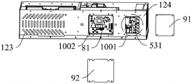
Referring to fig. 1, 4 and 7, a refrigerant filling valve 531 is disposed on the third pipeline 53 and near the evaporator 32, and the refrigerant filling valve 531 is mainly used for filling the pipeline 5 with refrigerant when the amount of refrigerant is small. In addition, since the third pipeline 53 is a low-pressure pipeline, in the present embodiment, the refrigerant filling valve 531 is disposed on the third pipeline 53, which facilitates the injection of the refrigerant. The housing 1 is provided with a first access opening 1001 in the fourth sidewall 124, and the first access opening 1001 is at least partially located with respect to the refrigerant charging valve 531. The shape of the first access opening 1001 may be rectangular, circular, oval, etc., without limitation. The fourth sidewall 124 is further provided with a first access cover 91 for sealing the first access opening 1001, and the first access cover 91 is fixed on the fourth sidewall 124 by screws, that is, when the first access cover 91 is not used for access, the second chamber 102 may be a closed space. The air conditioner is in the non-operating condition, just can take down first access cover plate 91 and fill the action of annotating the refrigerant.
The filling port of refrigerant filling valve 531 is inclined downwards and towards first access hole 1001, and after first access hole 91 is opened, refrigerant filling valve 531 can be seen, and filling equipment (not shown) can be connected with refrigerant filling valve 531 through first access hole 1001 quickly and conveniently to fill refrigerant. The first access opening 1001 is sized to allow the refrigerant filling valve 531 to be completely exposed and to accommodate an operating space when a lower filling device (not shown) is connected to the refrigerant filling valve 531.
Through set up refrigerant filling valve 531 on third pipeline 53 and set up first access hole 1001 on fourth lateral wall 124, make this application air conditioner need not take off the complete machine from the kitchen furred ceiling when filling the refrigerant, and only with several kitchen buckle near simple demolition first access hole 1001 of air conditioner, then open first access cover plate 91, fill refrigerant filling valve 531 and fill and annotate equipment (not shown) and couple together, accomplish refrigerant filling and annotate the back only with on being fixed in fourth lateral wall 124 again first access cover plate 91, install several kitchen buckle near first access hole 1001 can. The disassembly step and the re-hoisting step of the whole machine are omitted, the opening step and the re-fixing step of the upper cover of the machine are also omitted, the refrigerant filling flow is simplified, the workload of maintenance personnel is greatly reduced, time and labor are saved, and meanwhile, the labor cost is also reduced.
Referring to fig. 1 and 4, a second partition 14 is further disposed in the second chamber 102, and the second partition 14 has a first side plate 141 and a second side plate 142 connected to the first side plate 141. That is, in the present embodiment, the second partition 14 is provided in an L shape, but is not necessarily limited, and may be, for example, an arc shape. In this embodiment, the end of the first side plate 141 of the second partition 14 is connected to the first partition 13, and the end of the second side plate 142 is connected to the fourth side wall 124. Therefore, a third chamber 103 is formed between a portion of the first partition 13, a portion of the fourth side wall 124, and the second partition 14. It is not necessary that the two ends of the second partition 14 located in the second chamber 102 be connected to the first partition 13 and the fourth side wall 124, for example in other embodiments: the first side plate 141 of the second partition 14 may be connected at an end to the fourth side wall 124 and the second side plate 142 may be connected at an end to the fifth side wall 125, and the third chamber 103 may be defined by a portion of the fifth side wall 125, a portion of the fourth side wall 124, and the second partition 14.
In the present embodiment, the second partition 14 is a third chamber 103 that is formed by dividing a rectangular second chamber 102 into two chambers and accommodates the electronic control unit 8. Of course, in other embodiments, the second partition 14 may also be disposed in the first chamber 101, and then the second partition 14 divides the first chamber 101 into a part of space to form a third chamber 103 for accommodating the electronic control unit 8. It should be appreciated, of course, that the second partition 14 is disposed in the second chamber 102, which is an alternative embodiment, because the cold air after heat exchange circulates in the second chamber 102, and the electronic control unit 8 is disposed in the second chamber 102 for circulating the cold air, which is favorable for the operation stability of each electronic component in the electronic control unit 8.
The electronic control unit 8 includes an electronic control box 82 located in the third chamber 103, and the peripheral wall of the electronic control box 82 is fixedly connected to the fourth side wall 124. The electronic control unit 8 further includes an electronic control main board 81 disposed in the electronic control box 82 and provided with circuit elements, and other circuit elements disposed outside the electronic control box 82, and the electronic control main board 81 is fixed on a back board of the electronic control box 82 by screws.
Other circuit elements include a rectifying buck module 85. Since the condensing side fan 41 is a dc fan, it is necessary to supply dc power to the condensing side fan 41 for normal start and operation of the condensing side fan 41. In a specific implementation manner of the present application, the input end of the rectification voltage-reducing module 85 is connected to the electronic control main board 81, and the output end of the rectification voltage-reducing module is connected to the condensation-side fan 41, so that 220V of ac power on the electronic control main board 81 is rectified, reduced and converted into 24V of dc power through the rectification voltage-reducing module 85, and then is delivered to the condensation-side fan 41. In the present embodiment, the rectifying and voltage reducing module 85 is fixedly connected to the first side plate 141. In other embodiments, the rectified step-down module 85 may be fixedly connected to the second side plate 142 or the first partition plate 13. The space arrangement in the third chamber 103 is favorable for the heat dissipation of the rectification and voltage reduction module 85, and the other side of the second partition plate 14 is the second chamber 102 where the evaporator 32 is located, so that the heat dissipation of the rectification and voltage reduction module 85 can be further accelerated by the cold air cooled by the evaporator 32.
Other circuit components include a compressor capacitor 83 and an evaporator side fan capacitor 84. In the present embodiment, the compressor capacitor 83 is fixedly connected to the first partition plate 13. In other embodiments, the compressor capacitor 83 may be fixedly connected to the first side plate 141 or the second side plate 142 of the second partition 14. Compressor electric capacity 83 is established ties again to automatically controlled mainboard 81 after parallelly connected with compressor 2 to automatically controlled mainboard 81 can provide 220V's alternating current for compressor 2, and compressor electric capacity 83 is used for starting compressor 2. In the present embodiment, the evaporation-side fan capacitor 84 is fixedly connected to the first side plate 141. In other embodiments, the evaporator side fan capacitor 84 may be fixedly attached to the second side plate 142 of the first partition 13 or the second partition 14. The evaporation side fan capacitor 84 is connected in parallel with the evaporation side fan 42 and then connected in series to the electronic control main board 81, so that the electronic control main board 81 provides 220V alternating current for the evaporation side fan 42, and the evaporation side fan capacitor 84 is used for starting the evaporation side fan 42.
Referring to fig. 5, a strong current of 220V is provided on the electronic control main board 81, a rectifying and voltage-reducing module 85 connected to the electronic control main board 81 is a weak current of 24V, and the electronic control main board 81 is separated from the rectifying and voltage-reducing module 85 by the electronic control box 82, that is, the strong current and the weak current are separately provided, so that the safety is higher.
Referring to fig. 1, 7 and 8, a second access opening 1002 is disposed on the fourth side wall 124 where the electronic control box 82 is installed, and the size of the second access opening 1002 is such that all circuit components disposed on the electronic control main board 81 can be completely exposed and can accommodate an operation space for performing an access to the electronic control main board 81. The fourth side wall 124 is further provided with a second access cover 92 for closing the second access opening 1002, and the second access cover 92 is fixed on the fourth side wall 124 through screws. So set up, when automatically controlled mainboard 81 broke down, open second and overhaul apron 92 and can carry out troubleshooting and maintenance to automatically controlled mainboard 81.
Referring to fig. 1 and 9, in the present embodiment, a third access opening 1003 is also disposed on the bottom wall 11 below the rectification voltage reduction module 85, the size of the third access opening 1003 is such that the rectification voltage reduction module 85 can pass through the third access opening 1003, because the compressor capacitor 83 and the evaporation side fan capacitor 84 are generally smaller, the third access opening 1003 can also pass through the third access opening 1003, and the third access opening 1003 also needs to satisfy an operation space during maintenance. The bottom wall 11 is further provided with a third access cover plate 93 for sealing the third access opening 1003, and the third access cover plate 93 is fixed on the bottom wall 11 through screws. And the third maintenance cover plate 93 is opened, so that the compressor capacitor 83, the evaporation side fan capacitor 84 and the rectification voltage reduction module 85 can be subjected to troubleshooting and maintenance. In this embodiment, the third access opening 1003 is divided into two parts by the first side plate 141, one part of which is communicated with the third chamber 103 and can be used for checking a wiring fault and replacing the compressor capacitor 83 and the evaporation side fan capacitor 84, and the other part of which is communicated with the second chamber 102 and can be used for detaching and installing screws for fixing the rectification step-down module 85, thereby replacing the rectification step-down module 85.
Through set up second access hole 1002 and third access hole 1003 on fourth lateral wall 124 and diapire 11 respectively, can make kitchen furred ceiling air conditioner need not take off the complete machine from the kitchen furred ceiling when overhauing electric control unit 8, but only with several kitchen buckle near simply dismantling second access hole 1002 and/or third access hole 1003, then open second access cover 92 and/or third access cover 93 and carry out circuit fault investigation, only need close second access cover 92 and/or third access cover 93 after accomplishing the maintenance, install several kitchen buckle near second access hole 1002 and/or third access hole 1003 again can. The disassembly step and the re-hoisting step of the whole machine are omitted, the opening step and the re-fixing step of the upper cover of the machine are also omitted, the circuit maintenance flow is simplified, the workload of maintenance personnel is greatly reduced, time and labor are saved, and meanwhile, the labor cost is also reduced.
In fact, the second access opening 1002 does not have to be disposed on the fourth side wall 124, and may be disposed on the bottom wall 11 as the third access opening 1003, even the second access opening 1002 and the third access opening 1003 on the bottom wall 11 may be communicated to form a larger access opening, which satisfies both the need for repairing the electronic control main board 81 and the need for repairing other circuit components.
In summary, the refrigeration principle of the air conditioner of the present application is: kitchen air enters the first chamber 101 through the condensation side air inlet 1201 to exchange heat with the condenser 31, a high-temperature and high-pressure refrigerant is in the condenser 31, the high-temperature and high-pressure refrigerant can heat the air in the first chamber 101 in the heat exchange process with the air, and the heated hot air is discharged outdoors through the condensation side fan 41 and the condensation side air outlet 1203, which is equivalent to an outdoor unit in a split air conditioner. Kitchen air enters the second chamber 102 through the evaporation side air inlet 1202 to exchange heat with the evaporator 32, a refrigerant after being cooled and depressurized through the throttling element 521 is arranged in the evaporator 32, the low-temperature and low-pressure refrigerant can cool air in the second chamber 102 in the heat exchange process with the air, and the cooled cold air is sent into the room through the evaporation side fan 42 and the condensation side air outlet 1204, which is equivalent to an indoor unit in a split air conditioner.
The above embodiments are only used for illustrating the present invention and not for limiting the technical solutions described in the present application, and the present specification should be understood based on the descriptions of directions such as "front", "back", "left", "right", "upper", "lower", etc. for those skilled in the art, and although the present specification has described the present invention in detail with reference to the above embodiments, those skilled in the art should understand that those skilled in the art can still make modifications or equivalent substitutions on the present application, and all technical solutions and modifications thereof without departing from the spirit and scope of the present application should be covered in the claims of the present application.
Claims (10)
1. An air conditioner including a case (1), a compressor (2), a condenser (31), a condensing side fan (41), an evaporator (32), and an evaporating side fan (42), the case (1) having a first chamber (101) and a second chamber (102) spaced apart from each other, the compressor (2), the condenser (31), and the condensing side fan (41) being disposed in the first chamber (101), the evaporator (32) and the evaporating side fan (42) being disposed in the second chamber (102), characterized in that: the evaporator (32) is provided with an air inlet side and an air outlet side, the evaporation side fan (42) comprises a second motor (421), a second impeller (422) driven by the second motor (421) and a second casing (423) accommodating the second impeller (422), and the second casing (423) is provided with an air inlet facing the air outlet side of the evaporator (32).
2. The air conditioner according to claim 1, wherein: the shell (1) comprises a bottom wall (11) extending horizontally and a plurality of side walls (12) extending vertically from the bottom wall (11), the axial direction of the second motor (421) is parallel to the bottom wall (11), the second machine shell (423) is arranged around the axial direction of the second motor (421) and is vertically installed relative to the bottom wall (11), and therefore the air inlet of the second machine shell (423) faces the air outlet side of the evaporator (32).
3. The air conditioner according to claim 2, wherein: casing (1) includes first baffle (13), lateral wall (12) include first lateral wall (121), second lateral wall (122), third lateral wall (123), fourth lateral wall (124), fifth lateral wall (125) and sixth lateral wall (126) that end to end connected gradually, first lateral wall (121), second lateral wall (122), third lateral wall (123) with first baffle (13) enclose to be established the periphery of first cavity (101), fourth lateral wall (124), fifth lateral wall (125), sixth lateral wall (126) with first baffle (13) enclose to be established the periphery of second cavity (102), the air inlet side of evaporimeter (32) is towards fifth lateral wall (125), the air-out side of evaporimeter (32) dorsad fifth lateral wall (125) and towards first baffle (13).
4. The air conditioner according to claim 3, wherein: the air conditioner also comprises a metal support (7) for fixing the evaporation side fan (42) and the shell (1), wherein the metal support (7) comprises a main body part (70) and a fixing part bent from the main body part (70), a gap is formed between the main body part (70) and the first partition plate (13) at intervals, a through hole (700) is formed in the middle of the main body part (70), and the second motor (421) penetrates through the through hole (700) to enable the second motor (421) to be partially accommodated in the gap.
5. The air conditioner according to claim 4, wherein: the fixing part comprises a first folding edge (71), a second folding edge (72) and a third folding edge (73) which are positioned on different sides of the main body part (70), the first folding edge (71) is fixedly connected with the first partition board (13), the second folding edge (72) is fixedly connected with the bottom wall (11) or the first partition board (13), and the third folding edge (73) is fixedly connected with the sixth side wall (126) or the first partition board (13).
6. The air conditioner according to claim 3, wherein: the evaporator (32) is fixedly arranged on the inner wall surface of the fifth side wall (125), the fifth side wall (125) is provided with an evaporation side air inlet (1202), the sixth side wall (126) is provided with an evaporation side air inlet (1204), the condensation side fan (41) is fixedly arranged on the inner wall surface of the first side wall (121), the condenser (31) is fixedly arranged on the inner wall surface of the second side wall (122) and/or the inner wall surface of the third side wall (123), the second side wall (122) and/or the third side wall (123) is provided with a condensation side air inlet (1201), and the first side wall (121) is provided with a condensation side air outlet (1203).
7. The air conditioner according to claim 6, wherein: the condensation side fan (41) comprises a first motor (411) and two first impellers which are respectively arranged at two axial ends of the first motor (411) and driven by the first motor (411) at the same time, the number of the condensation side air outlets (1203) is two, and the two condensation side air outlets (1203) are arranged corresponding to one first impeller.
8. The air conditioner according to claim 6, wherein: the compressor (2) has a discharge port, the compressor (2) comprises a head part (21) and a tail part (22) which are arranged along the length direction of the compressor (2), and the discharge port of the compressor (2) is arranged closer to the head part (21); the tail (22) is closer to the condenser side fan (41) than the head (21) in a length direction of the compressor (2).
9. The air conditioner according to claim 3, wherein: the electric control unit (8) is electrically connected with the compressor (2), the condensation side fan (41) and the evaporation side fan (42), the shell (1) comprises a second partition plate (14), one end of the second partition plate (14) is connected to the first partition plate (13), and the other end of the second partition plate (14) is connected to the fourth side wall (124); the air conditioner also comprises a third chamber (103) used for accommodating the electronic control unit (8), and a part of the first partition plate (13), a part of the fourth side wall (124) and the second partition plate (14) are enclosed on the periphery of the third chamber (103).
10. The air conditioner according to claim 9, wherein: the condensation side fan (41) is a direct current fan, the evaporation side fan (42) is an alternating current fan, the electric control unit (8) comprises an electric control box (82), an electric control main board (81) located in the electric control box (82) and a rectification voltage reduction module (85) located outside the electric control box (82), the electric control main board (81) supplies strong current to the evaporation side fan (42), and the electric control main board (81) supplies weak current to the condensation side fan (41) through the rectification voltage reduction module (85).
Priority Applications (1)
| Application Number | Priority Date | Filing Date | Title |
|---|---|---|---|
| CN202122404400.7U CN216620058U (en) | 2021-09-30 | 2021-09-30 | Air conditioner |
Applications Claiming Priority (1)
| Application Number | Priority Date | Filing Date | Title |
|---|---|---|---|
| CN202122404400.7U CN216620058U (en) | 2021-09-30 | 2021-09-30 | Air conditioner |
Publications (1)
| Publication Number | Publication Date |
|---|---|
| CN216620058U true CN216620058U (en) | 2022-05-27 |
Family
ID=81691210
Family Applications (1)
| Application Number | Title | Priority Date | Filing Date |
|---|---|---|---|
| CN202122404400.7U Active CN216620058U (en) | 2021-09-30 | 2021-09-30 | Air conditioner |
Country Status (1)
| Country | Link |
|---|---|
| CN (1) | CN216620058U (en) |
-
2021
- 2021-09-30 CN CN202122404400.7U patent/CN216620058U/en active Active
Similar Documents
| Publication | Publication Date | Title |
|---|---|---|
| CN102759151A (en) | Outdoor unit for air conditioner | |
| CN106461243A (en) | Outdoor unit of an air conditioner and method of manufacturing the same | |
| CN216620058U (en) | Air conditioner | |
| CN216620059U (en) | Air conditioner | |
| CN217584647U (en) | Air conditioner | |
| CN217083041U (en) | Piston type evaporation and cooling integrated machine | |
| CN217584646U (en) | Air conditioner | |
| CN101644462A (en) | Indoor unit of air conditioner | |
| CN217584645U (en) | Air conditioner | |
| CN115899845A (en) | Air conditioner | |
| CN220041977U (en) | Air conditioner | |
| CN209358423U (en) | Frequency converter | |
| CN219435969U (en) | Air conditioner | |
| CN220042033U (en) | Air conditioner | |
| CN220038626U (en) | Air conditioner | |
| CN217929005U (en) | Integrated air conditioner for kitchen | |
| CN213020028U (en) | Outdoor machine of air conditioner | |
| CN214501434U (en) | Indoor unit of air conditioner | |
| CN218442598U (en) | Energy storage cabinet cold water air conditioner | |
| CN210959286U (en) | Air conditioning device for outdoor cabinet | |
| CN215723607U (en) | Cabinet-level refrigerating system | |
| CN215808899U (en) | Kitchen air conditioner | |
| CN214501443U (en) | Indoor unit of air conditioner | |
| CN217559962U (en) | Indoor unit of air conditioner | |
| CN214501435U (en) | Indoor unit of air conditioner |
Legal Events
| Date | Code | Title | Description |
|---|---|---|---|
| GR01 | Patent grant | ||
| GR01 | Patent grant | ||
| TR01 | Transfer of patent right | ||
| TR01 | Transfer of patent right |
Effective date of registration: 20231107 Address after: No. 101, Shichong Lane, Binjiang District, Hangzhou, Zhejiang 310052 Patentee after: HANGZHOU R&D DESIGN PLC Address before: 310052 room 205, floor 2, building 3, No. 365, Changjiang Road, Hangzhou, Zhejiang Patentee before: Hangzhou Jingxiang Technology Co.,Ltd. |