CN216609852U - Hardware shaft sleeve part stamping die - Google Patents
Hardware shaft sleeve part stamping die Download PDFInfo
- Publication number
- CN216609852U CN216609852U CN202122892945.7U CN202122892945U CN216609852U CN 216609852 U CN216609852 U CN 216609852U CN 202122892945 U CN202122892945 U CN 202122892945U CN 216609852 U CN216609852 U CN 216609852U
- Authority
- CN
- China
- Prior art keywords
- bottom plate
- stamping die
- wall
- die
- sleeve part
- Prior art date
- Legal status (The legal status is an assumption and is not a legal conclusion. Google has not performed a legal analysis and makes no representation as to the accuracy of the status listed.)
- Active
Links
Images


Abstract
The utility model discloses a stamping die for a hardware shaft sleeve part, which comprises a die top cover, wherein an injection molding hole is formed in the inner wall of the die top cover, four groups of fixing rods are arranged on the outer surface of the lower end of the die top cover, a first shaping piece is arranged at the lower end of the die top cover and is positioned on the outer surface of the upper end of a first bottom plate, a second bottom plate is arranged at one end of the first bottom plate, a pull rod is arranged on the inner wall of the second bottom plate, and a butt joint is arranged on the outer surface of one side of the first shaping piece. According to the stamping die for the hardware shaft sleeve part, the top cover of the stamping die is arranged to be conveniently covered on the first shaping piece for injection molding, the drawing rod and the second shaping piece are arranged to facilitate die shaping and demolding, the fixing rod is convenient for fixing the first base plate and the second base plate, the auxiliary base plate is embedded into the inner wall of the first base plate, the stamping die is convenient to mold, and good use prospects are brought.
Description
Technical Field
The utility model relates to the technical field of stamping dies, in particular to a stamping die for a hardware shaft sleeve part.
Background
The stamping forming is a stamping method for directly copying and forming a blank or a semi-finished workpiece in the shape of a convex die and a concave die according to engineering drawings, a hardware shaft sleeve is a cylindrical mechanical part sleeved on a rotating shaft, is a component of a sliding bearing, belongs to one of hardware fittings, and needs to use a corresponding stamping die in the production and use process.
When current five metals axle sleeve stamping die is installed and is used, the drawing of patterns of the axle sleeve of being not convenient for after the axle sleeve shaping, the mandatory drawing of patterns can reduce the quality of product, and the use of giving people has brought certain adverse effect, and in order to solve prior art's not enough, we provide a five metals axle sleeve part stamping die.
SUMMERY OF THE UTILITY MODEL
Technical problem to be solved
Aiming at the defects of the prior art, the utility model provides a stamping die for a hardware shaft sleeve part, which has the advantages of convenience in injection molding, demolding and use and the like, and can effectively solve the problems in the background art.
(II) technical scheme
In order to realize the purpose, the utility model adopts the technical scheme that: the utility model provides a five metals axle sleeve part stamping die, includes the mould top cap, the inner wall of mould top cap is provided with the hole of moulding plastics, the lower extreme surface of mould top cap is provided with four dead levers of group, the lower extreme of mould top cap is provided with the design No. one, the upper end surface that the design is located the bottom plate No. one, the one end of bottom plate is provided with the bottom plate No. two, the inner wall of bottom plate No. two is provided with the pull pole, one side surface of the design No. one is provided with the butt joint.
Preferably, a fixing piece is arranged between the fixing rod and the top cover of the die, and the outer surface of the upper end of the fixing rod is fixedly connected with the outer surface of the lower end of the top cover of the die through the fixing piece.
Preferably, be provided with the mounting No. two between butt joint and the setting piece, the surface of one side of butt joint is through the fixed connection of mounting No. two with the surface of one side of setting piece.
Preferably, the inner surface of the upper end of the first bottom plate is provided with a fixing hole, the inner wall of the first bottom plate is provided with a movable groove, the inside of the first shaping piece is provided with a second shaping piece, the outer surface of the lower end of the second shaping piece is provided with an auxiliary chassis, the outer wall of the auxiliary chassis is provided with a loading block, and the outer surfaces of two sides of the pull rod are provided with limit blocks.
Preferably, a clamping piece is arranged between the auxiliary chassis and the first bottom plate, and the outer wall of the auxiliary chassis is detachably connected with the inner wall of the first bottom plate through the clamping piece.
Preferably, a third fixing piece is arranged between the limiting block and the pull rod, and the outer surface of one side of the limiting block is fixedly connected with the outer surface of one side of the pull rod through the third fixing piece.
(III) advantageous effects
Compared with the prior art, the utility model provides a stamping die for a hardware shaft sleeve part, which has the following beneficial effects:
1. this five metals axle sleeve part stamping die, through the mould top cap that sets up, be convenient for cover on the setting element, so that mould plastics, consider to mould injection moulding to the mould, here with the raw materials of moulding plastics through the inside of moulding plastics hole injection mould top cap and a setting element, then cooling forming, a bottom plate and No. two bottom plates are convenient for part, and in order to avoid the two to part at the in-process of moulding plastics, with the dead lever card on the fixed orifices of a bottom plate inside, thus, the separation of a bottom plate and No. two bottom plates has received the restriction of dead lever, the raw materials of moulding plastics are being wrapped up to a setting element, the mould of being convenient for is stereotyped.
2. This five metals axle sleeve part stamping die, pull pole and No. two design through the setting, the design of the mould of being convenient for, convenient drawing of patterns simultaneously, for convenient drawing of patterns, here after the cooling of moulding plastics is accomplished, take away mould top cap and dead lever from the bottom plate, then pull open No. two bottom plates from the bottom plate above, here the stopper is installed in the inside of bottom plate, that is to say No. two bottom plates and a bottom plate be a whole, be inconvenient separately, so draw out for the convenience of showing the structure in the picture, then slowly take out the outer wall upper end of forming part from No. two design pieces, supplementary chassis is through loading the piece and installs the inner wall at a bottom plate, then dock No. two bottom plates with a bottom plate again, carry out the next time of moulding plastics.
Drawings
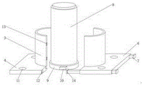
Fig. 1 is a schematic overall structure diagram of a stamping die for a hardware shaft sleeve part according to the utility model.
Fig. 2 is a schematic structural diagram of a die top cover of the stamping die for the hardware shaft sleeve part.
Fig. 3 is a schematic structural diagram of a second shaped part and a first shaped part of the stamping die for the hardware shaft sleeve part according to the utility model.
Fig. 4 is an exploded view of the stamping die for the hardware shaft sleeve part according to the utility model.
In the figure: 1. a mold top cover; 2. fixing the rod; 3. a first sizing member; 4. a first bottom plate; 5. injection molding holes; 6. a second bottom plate; 7. a pull rod; 8. a second fixed part; 9. an auxiliary chassis; 10. a loading block; 11. a fixing hole; 12. a movable groove; 13. a butt joint; 14. and a limiting block.
Detailed Description
In order to make the technical means, the creation characteristics, the achievement purposes and the effects of the utility model easy to understand, the utility model is further described with the specific embodiments.
In the first embodiment, referring to fig. 1-4, a stamping die for a hardware shaft sleeve part comprises a die top cover 1, wherein an injection hole 5 is formed in the inner wall of the die top cover 1, four groups of fixing rods 2 are arranged on the outer surface of the lower end of the die top cover 1, a first shaping piece 3 is arranged at the lower end of the die top cover 1, the first shaping piece 3 is arranged on the outer surface of the upper end of a first base plate 4, a second base plate 6 is arranged at one end of the first base plate 4, a drawing rod 7 is arranged on the inner wall of the second base plate 6, a butt joint 13 is arranged on the outer surface of one side of the first shaping piece 3, in consideration of injection molding of a die, injection molding raw materials are injected into the die top cover 1 and the first shaping piece 3 through the injection hole 5 and then are cooled to be molded, the first base plate 4 and the second base plate 6 are conveniently separated, and are blocked on a fixing hole 11 in the first base plate 4 by the fixing rods 2 in order to avoid the separation of the two in the injection molding process, like this, the separation of No. one bottom plate 4 and No. two bottom plates 6 has received the restriction of dead lever 2, and the injection moulding raw materials is wrapped up in design piece 3, the mould of being convenient for is stereotyped.
A fixing piece is arranged between the fixing rod 2 and the die top cover 1, the outer surface of the upper end of the fixing rod 2 is fixedly connected with the outer surface of the lower end of the die top cover 1 through the fixing piece, and the fixing rod 2 is convenient for fixing the first bottom plate 4 and the second bottom plate 6.
A fixing piece II is arranged between the butt joint 13 and the first shaping piece 3, the outer surface of one side of the butt joint 13 is fixedly connected with the outer surface of one side of the first shaping piece 3 through the fixing piece II, and the butt joint 13 is convenient for butt joint of the shaping pieces.
Embodiment two, please refer to fig. 1-4, based on embodiment one, the inner surface of the upper end of the first bottom plate 4 is provided with a fixing hole 11, the inner wall of the first bottom plate 4 is provided with a movable groove 12, the inside of the first shaped part 3 is provided with a second shaped part 8, the outer surface of the lower end of the second shaped part 8 is provided with an auxiliary chassis 9, the outer wall of the auxiliary chassis 9 is provided with a loading block 10, the outer surfaces of both sides of the pull-out rod 7 are provided with a limiting block 14, for demolding convenience, after the injection molding and cooling are completed, the top cover 1 and the fixing rod 2 of the mold are taken away from the first bottom plate 4, then the second bottom plate 6 is pulled away from the first bottom plate 4, wherein the limiting block 14 is installed inside the first bottom plate 4, that is to say, the second bottom plate 6 and the first bottom plate 4 are integrated and are not convenient to be separated, the drawing is drawn for convenience of structure representation, then the formed part is slowly taken out from the upper end of the outer wall of the second sizing part 8, the auxiliary chassis 9 is installed on the inner wall of the first bottom plate 4 through the loading block 10, and then the second bottom plate 6 is butted with the first bottom plate 4 again for next injection molding.
Be provided with the fastener between supplementary chassis 9 and bottom plate 4, the outer wall of supplementary chassis 9 can be dismantled with the inner wall of bottom plate 4 through the fastener and be connected, and supplementary chassis 9 is used for imbedding the inner wall of bottom plate 4, makes things convenient for the mould to stereotype.
A third fixing piece is arranged between the limiting block 14 and the drawing rod 7, the outer surface of one side of the limiting block 14 is fixedly connected with the outer surface of one side of the drawing rod 7 through the third fixing piece, and the limiting block 14 is convenient for keeping the connection between the first bottom plate 4 and the second bottom plate 6.
Principle of operation
When the mold is used, the top cover 1 of the mold is arranged to be conveniently covered on the first shaping piece 3 for injection molding, and in consideration of injection molding of the mold, injection molding raw materials are injected into the top cover 1 of the mold and the first shaping piece 3 of the mold through the injection molding holes 5 and then are cooled and molded, the first bottom plate 4 and the second bottom plate 6 are conveniently separated, and in order to avoid separation of the first bottom plate and the second bottom plate, the fixing rods 2 are clamped on the fixing holes 11 in the first bottom plate 4 in the injection molding process, so that the separation of the first bottom plate 4 and the second bottom plate 6 is limited by the fixing rods 2, and the injection molding raw materials are wrapped by the first shaping piece 3 to facilitate mold shaping; drawing pole 7 and No. two design 8 of setting, the design of the mould of being convenient for, the convenient drawing of patterns simultaneously, for the convenience drawing of patterns, here after the cooling of moulding plastics is accomplished, take away mould top cap 1 and dead lever 2 from a bottom plate 4, then pull open No. two bottom plates 6 from a bottom plate 4, stopper 14 here is installed in the inside of a bottom plate 4, that is to say No. two bottom plates 6 and a bottom plate 4 are a whole, be inconvenient separately, it so draws out to represent the structure in the picture for the convenience, then slowly take out the formed part from No. two design 8's outer wall upper end, supplementary chassis 9 is installed at a bottom plate 4's inner wall through loading piece 10, then dock No. two bottom plates 6 with a bottom plate 4 again, carry out the next time of moulding plastics.
It is noted that, herein, relational terms such as first and second (a, b, etc.) and the like may be used solely to distinguish one entity or action from another entity or action without necessarily requiring or implying any actual such relationship or order between such entities or actions. Also, the terms "comprises," "comprising," or any other variation thereof, are intended to cover a non-exclusive inclusion, such that a process, method, article, or apparatus that comprises a list of elements does not include only those elements but may include other elements not expressly listed or inherent to such process, method, article, or apparatus. Without further limitation, an element defined by the phrase "comprising an … …" does not exclude the presence of other identical elements in a process, method, article, or apparatus that comprises the element.
The foregoing shows and describes the general principles and broad features of the present invention and advantages thereof. It will be understood by those skilled in the art that the present invention is not limited to the embodiments described above, which are described in the specification and illustrated only to illustrate the principle of the present invention, but that various changes and modifications may be made therein without departing from the spirit and scope of the present invention, which fall within the scope of the utility model as claimed.
Claims (6)
1. The utility model provides a five metals axle sleeve part stamping die, includes mould top cap (1), its characterized in that: the inner wall of mould top cap (1) is provided with injection molding hole (5), the lower extreme surface of mould top cap (1) is provided with four dead levers of group (2), the lower extreme of mould top cap (1) is provided with a standard part (3), a standard part (3) is located the upper end surface of bottom plate (4) No. one, the one end of bottom plate (4) is provided with bottom plate (6) No. two, the inner wall of bottom plate (6) No. two is provided with pull pole (7), one side surface of a standard part (3) is provided with butt joint (13).
2. The hardware shaft sleeve part stamping die of claim 1, wherein: a fixing piece is arranged between the fixing rod (2) and the die top cover (1), and the outer surface of the upper end of the fixing rod (2) is fixedly connected with the outer surface of the lower end of the die top cover (1) through the fixing piece.
3. The hardware shaft sleeve part stamping die of claim 1, wherein: be provided with No. two mountings between butt joint (13) and a decide type spare (3), one side surface fixed connection of one side of butt joint (13) through No. two mountings and a decide type spare (3).
4. The hardware shaft sleeve part stamping die of claim 1, wherein: the utility model discloses a pull rod, including bottom plate (4), the inner wall of bottom plate (4) is provided with activity groove (12), the inside of a type piece (3) is provided with No. two type pieces (8), the lower extreme surface of No. two type pieces (8) is provided with auxiliary chassis (9), the outer wall of auxiliary chassis (9) is provided with loads piece (10), the both sides surface of pull rod (7) all is provided with stopper (14).
5. The hardware shaft sleeve part stamping die of claim 4, wherein: a clamping piece is arranged between the auxiliary chassis (9) and the first bottom plate (4), and the outer wall of the auxiliary chassis (9) is detachably connected with the inner wall of the first bottom plate (4) through the clamping piece.
6. The hardware shaft sleeve part stamping die of claim 4, wherein: a third fixing piece is arranged between the limiting block (14) and the drawing rod (7), and the outer surface of one side of the limiting block (14) is fixedly connected with the outer surface of one side of the drawing rod (7) through the third fixing piece.
Priority Applications (1)
| Application Number | Priority Date | Filing Date | Title |
|---|---|---|---|
| CN202122892945.7U CN216609852U (en) | 2021-11-24 | 2021-11-24 | Hardware shaft sleeve part stamping die |
Applications Claiming Priority (1)
| Application Number | Priority Date | Filing Date | Title |
|---|---|---|---|
| CN202122892945.7U CN216609852U (en) | 2021-11-24 | 2021-11-24 | Hardware shaft sleeve part stamping die |
Publications (1)
| Publication Number | Publication Date |
|---|---|
| CN216609852U true CN216609852U (en) | 2022-05-27 |
Family
ID=81696803
Family Applications (1)
| Application Number | Title | Priority Date | Filing Date |
|---|---|---|---|
| CN202122892945.7U Active CN216609852U (en) | 2021-11-24 | 2021-11-24 | Hardware shaft sleeve part stamping die |
Country Status (1)
| Country | Link |
|---|---|
| CN (1) | CN216609852U (en) |
-
2021
- 2021-11-24 CN CN202122892945.7U patent/CN216609852U/en active Active
Similar Documents
| Publication | Publication Date | Title |
|---|---|---|
| CN206614718U (en) | A kind of plastic mould with automatic demoulding functions | |
| CN216609852U (en) | Hardware shaft sleeve part stamping die | |
| CN208576151U (en) | Anti-sticking chamber combination ejection molding high-precision mold | |
| CN207859370U (en) | A kind of pickoff of plastic mould | |
| CN214820515U (en) | Forming die is used in plastic product preparation | |
| CN211030935U (en) | Polytetrafluoroethylene high-stroke mold pressing rod mold | |
| CN205522314U (en) | Plastic bowl cover injection mold | |
| CN210634034U (en) | Mould is used in rubber cell phone case preparation | |
| CN211727425U (en) | Integral demolding and die-casting die with inner insert | |
| CN216760632U (en) | Processing subassembly based on polyimide film sticky tape | |
| CN209633659U (en) | A kind of support bar mould | |
| CN210501178U (en) | Mould that machining precision is high | |
| CN111421770A (en) | Mould of filter plate handle of moulding plastics | |
| CN213728790U (en) | Drawing die for producing automobile reinforcing plate | |
| CN219055247U (en) | Shell mould convenient for demoulding | |
| CN216708252U (en) | Mould for injection molding of milk tea cup | |
| CN205851660U (en) | A kind of hi-Fix stretching die | |
| CN209616212U (en) | The plastic mould of anti-mold insert deformation | |
| CN219055227U (en) | In-mold injection molding mechanism for producing automobile parts with high molding quality | |
| CN213618072U (en) | Telephone casing device of moulding plastics convenient to drawing of patterns | |
| CN219132973U (en) | Mould for mould pressing composite bipolar plate | |
| CN204585739U (en) | A kind of air-conditining dash receiver bracket mould of improvement | |
| CN216578798U (en) | Pipe mould capable of automatically ejecting mould core | |
| CN208497489U (en) | A kind of easily demoulding plastic mould | |
| CN215849360U (en) | Recyclable precision mold |
Legal Events
| Date | Code | Title | Description |
|---|---|---|---|
| GR01 | Patent grant | ||
| GR01 | Patent grant |