CN216608142U - Become two-sided milling fixture of primary mould - Google Patents
Become two-sided milling fixture of primary mould Download PDFInfo
- Publication number
- CN216608142U CN216608142U CN202123184331.XU CN202123184331U CN216608142U CN 216608142 U CN216608142 U CN 216608142U CN 202123184331 U CN202123184331 U CN 202123184331U CN 216608142 U CN216608142 U CN 216608142U
- Authority
- CN
- China
- Prior art keywords
- rough surface
- workstation
- sided milling
- workpiece
- support frame
- Prior art date
- Legal status (The legal status is an assumption and is not a legal conclusion. Google has not performed a legal analysis and makes no representation as to the accuracy of the status listed.)
- Active
Links
Images

Abstract
The utility model relates to a double-sided milling fixture for a primary mold, which is applied to the technical field of milling fixtures and solves the problem that the end surface to be processed of a workpiece and the cutting surface of a milling cutter are not easy to be on the same plane, so that the milling precision is reduced; when the shape of a workpiece to be machined is not uniform, clamping deviation is easy to occur in the machining process, and the problem of low positioning precision is caused; the clamping position of the workpiece by the pressing clamp can be conveniently adjusted, the end face of the workpiece to be processed and the cutting face of the milling cutter are ensured to be on the same plane, and the milling precision is improved.
Description
Technical Field
The utility model is applied to the technical field of milling clamps, and particularly relates to a double-sided milling clamp for a primary forming die.
Background
The primary mould is a mould for producing various glass bottles, and along with the research and development and improvement of a line and row machine of a glass manufacturer, the outer skin of the mould is required to be milled flat so as to meet the requirements of the line and row machine. Current patent publication No. CN 210703742U has announced a two-sided milling hydraulically operated fixture, and it includes that two-sided milling workstation, mounting groove, fixture base, backing plate, portal frame, hydraulic cylinder, piston rod, compress tightly anchor clamps, two-sided milling workstation upper surface parallel arrangement has a plurality of mounting grooves, fixture base passes through the bolt to be fixed on two-sided milling workstation with the cooperation of mounting groove, fixture base upper surface parallel arrangement has a plurality of mounting grooves, and is a plurality of the backing plate passes through the bolt to be fixed on fixture base with the cooperation of mounting groove, still install the portal frame on the fixture base, invert on the portal frame and install a plurality of hydraulic cylinder, hydraulic cylinder compresses tightly anchor clamps through piston rod down. Although the clamp improves the processing efficiency, when a workpiece is placed in the clamp, the end surface to be processed of the workpiece and the cutting surface of the milling cutter are not easy to be in the same plane, thereby reducing the milling precision; in addition, when the shape of the workpiece to be machined is not uniform, clamping deviation is easy to occur in the machining process, and positioning accuracy is low.
SUMMERY OF THE UTILITY MODEL
The utility model aims to provide a double-sided milling clamp for a primary die, which solves the problem that the end surface to be processed of a workpiece and the cutting surface of a milling cutter are not easy to be on the same plane, so that the milling precision is reduced; in addition, when the shape of the workpiece to be machined is not uniform, clamping deviation is easy to occur in the machining process, and the problem of low positioning precision is caused.
In order to achieve the purpose, the utility model adopts the technical scheme that:
the utility model provides a double-sided milling clamp for an initial mold, which comprises a workbench, an inverted U-shaped support frame arranged on the workbench, a base plate arranged on the upper end surface of the workbench, and a pressing assembly, wherein the bottom end of the inverted U-shaped support frame is fixed with the workbench through a bolt, the pressing assembly comprises a hydraulic cylinder and a pressing clamp, the hydraulic cylinder is arranged on a cross rod of the inverted U-shaped support frame, the pressing clamp is connected with the hydraulic cylinder through a piston connecting rod, a limiting plate is arranged on one side surface of the workbench along the length direction of the workbench, and the limiting plate is detachably connected with the workbench.
Furthermore, the workstation is provided with the guide way along its width direction's both sides face, the bottom of the two risers of the support frame of falling U-shaped be provided with the spacing arch of guide way complex.
Further, the limiting plate is the setting of falling U-shaped, the bottom of two risers of limiting plate all is provided with fixed cardboard, on the workstation with the position that fixed cardboard corresponds is provided with the fixed block, fixed cardboard with the fixed block is fixed through the pin.
Furthermore, the backing plate is in a flat plate shape, the upper surface of the backing plate is symmetrically provided with a first rough surface, a second rough surface, a third rough surface and a fourth rough surface, and the cross sections of the first rough surface, the second rough surface, the third rough surface and the fourth rough surface are in a tooth-shaped structure.
Furthermore, the compressing clamp is of a square-shaped structure, and four corners of the lower bottom surface are provided with pyramids protruding downwards.
Due to the application of the technical scheme, compared with the prior art, the utility model has the following advantages:
according to the double-sided milling clamp for the primary mold, a workpiece to be milled is fixed through the double-sided milling clamp, so that the subsequent milling cutter can mill the workpiece conveniently, the processing precision and the yield are improved, and the operation risk coefficient is low; meanwhile, the inverted U-shaped support frame can move along the length direction of the workbench conveniently through the matching of the bolt connection and the limiting protrusion and the guide groove, so that the clamping position of the pressing clamp on the workpiece can be adjusted conveniently. A limiting plate is arranged on one side surface of the workbench along the length direction of the workbench, the position of the workpiece is limited by the limiting plate, the end surface of the workpiece to be processed and the cutting surface of the milling cutter are ensured to be on the same plane, and the milling precision is improved.
Drawings
Some specific embodiments of the utility model will be described in detail hereinafter, by way of illustration and not limitation, with reference to the accompanying drawings. The same reference numbers in the drawings identify the same or similar elements or components. Those skilled in the art will appreciate that the drawings are not necessarily drawn to scale. In the drawings:
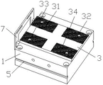
FIG. 1 is a schematic view of the overall structure in an embodiment of the present invention;
fig. 2 is a schematic diagram showing a structure of a workbench according to an embodiment of the present invention.
Wherein the reference numerals are as follows:
1. a work table; 2. an inverted U-shaped support frame; 3. a base plate; 31. a first rough pitted surface; 32. a second rough pitted surface; 33. a third rough pitted surface; 34. fourth rough pitted surface; 4. a compression assembly; 41. a hydraulic cylinder; 42. compressing the clamp; 43. a piston connecting rod; 5. a guide groove; 6. a limiting bulge; 7. a limiting plate; 8. fixing the clamping plate; 9. a fixed block; 10. a pyramid.
Detailed Description
The technical solutions of the present invention will be described clearly and completely with reference to the accompanying drawings, and it should be understood that the described embodiments are some, but not all embodiments of the present invention. All other embodiments, which can be derived by a person skilled in the art from the embodiments given herein without making any creative effort, shall fall within the protection scope of the present invention.
In the description of the present invention, it should be noted that the terms "center", "upper", "lower", "left", "right", "vertical", "horizontal", "inner", "outer", etc., indicate orientations or positional relationships based on the orientations or positional relationships shown in the drawings, and are only for convenience of description and simplicity of description, but do not indicate or imply that the device or element being referred to must have a particular orientation, be constructed and operated in a particular orientation, and thus, should not be construed as limiting the present invention. Furthermore, the terms "first," "second," and "third" are used for descriptive purposes only and are not to be construed as indicating or implying relative importance.
In addition, the technical features involved in the different embodiments of the present invention described below may be combined with each other as long as they do not conflict with each other.
Referring to fig. 1 and 2, for the double-sided milling fixture for the blank mold provided by the utility model, the double-sided milling fixture comprises a workbench 1 and an inverted U-shaped support frame 2 arranged on the workbench 1, the bottom end of the inverted U-shaped support frame 2 is fixed with the workbench 1 through a bolt, a backing plate 3 is arranged on the upper end surface of the workbench 1, the backing plate 3 is in a flat plate shape, the upper surface of the backing plate 3 is symmetrically provided with a first rough surface 31, a second rough surface 32, a third rough surface 33 and a fourth rough surface 34, the cross sections of the first rough surface 31, the second rough surface 32, the third rough surface 33 and the fourth rough surface 34 are in a toothed structure, and when a workpiece is placed on the backing plate 3, the friction force between the workpiece and the workpiece is increased through the first rough surface 31, the second rough surface 32, the third rough surface 33 and the fourth rough surface 34, so that the workpiece placed on the backing plate 3 is not easy to slide; the pressing device is characterized by further comprising a pressing assembly 4, wherein the pressing assembly 4 comprises a hydraulic cylinder 41 and a pressing clamp 42, the hydraulic cylinder 41 is arranged on a cross rod of the inverted U-shaped support frame 2, the pressing clamp 42 is connected with the hydraulic cylinder 41 through a piston connecting rod 43, the pressing clamp 42 is connected with the piston connecting rod 43 through a universal shaft, and a workpiece placed on the base plate 3 is fixed through the hydraulic assembly 4; wherein, be provided with guide way 5 on workstation 1 along its width direction's both sides face, the bottom of two risers of the support frame of falling U-shaped 2 be provided with guide way 5 complex spacing arch 6, through bolted connection and spacing arch 6 and guide way 5's cooperation, conveniently realize falling U-shaped support frame 2 along the length direction's of workstation 1 removal to be convenient for adjust the clamping position of clamp 4 to the work piece. Be provided with limiting plate 7 along its length direction's a side at workstation 1, limiting plate 7 is the setting of falling the U-shaped, and the bottom of two risers of limiting plate 7 all is provided with fixed cardboard 8, and the position that corresponds with fixed cardboard 8 on workstation 1 is provided with fixed block 9, and fixed cardboard 8 passes through the pin with fixed block 9 and fixes, prescribes a limit to the position of work piece through limiting plate 7, guarantees that the terminal surface and the milling cutter cutting face of work piece pending are on the coplanar, improves and mills the precision.
Further, referring to fig. 1 and 2, the pressing fixture 4 is a square structure, and four corners of the lower bottom surface are provided with pyramids 10 protruding downward, that is, four surfaces of the pressing fixture 4 are all in a trapezoidal arrangement, so that the pressing fixture 4 better fits round workpieces.
In summary, the following steps: the double-sided milling fixture is used for fixing a workpiece to be milled, so that the subsequent milling cutter can mill the workpiece conveniently, the processing precision and the yield are improved, and the operation risk coefficient is low; meanwhile, the inverted U-shaped support frame 2 can be conveniently moved along the length direction of the workbench 1 through the matching of the bolt connection and the limiting bulge 6 with the guide groove 5, so that the clamping position of the pressing clamp 4 to the workpiece can be conveniently adjusted. A limiting plate 7 is arranged on one side surface of the workbench 1 along the length direction of the workbench, the position of the workpiece is limited by the limiting plate 7, the end surface of the workpiece to be processed and the cutting surface of the milling cutter are ensured to be on the same plane, and the milling precision is improved.
The above embodiments are merely illustrative of the technical concept and features of the present invention, and the purpose thereof is to enable those skilled in the art to understand the content of the present invention and implement the utility model, and not to limit the scope of the utility model, and all equivalent changes or modifications made according to the spirit of the present invention should be covered by the scope of the present invention.
Claims (5)
1. The utility model provides a become two-sided milling fixture of primary mould, a serial communication port, be in including workstation and setting the support frame of falling the U-shaped on the workstation, the bottom of the support frame of falling the U-shaped with the workstation passes through the bolt fastening, the up end of workstation is provided with the backing plate, still including compressing tightly the subassembly, it includes the pneumatic cylinder and compresses tightly anchor clamps to compress tightly the subassembly, the pneumatic cylinder sets up on the horizontal pole of the support frame of falling the U-shaped, compress tightly anchor clamps pass through piston rod with the pneumatic cylinder is connected, the workstation is provided with the limiting plate along its length direction's a side, the limiting plate with the connection can be dismantled to the workstation.
2. The primary mold forming die double-sided milling fixture as claimed in claim 1, wherein the worktable is provided with guide grooves on both sides along the width direction thereof, and the bottom ends of the two risers of the inverted U-shaped support frame are provided with limit protrusions engaged with the guide grooves.
3. The primary mold forming die double-sided milling fixture as claimed in claim 1 or 2, wherein the limiting plate is in an inverted U shape, the bottom ends of two vertical plates of the limiting plate are provided with fixing clamping plates, the position on the workbench corresponding to the fixing clamping plates is provided with fixing blocks, and the fixing clamping plates are fixed with the fixing blocks through pins.
4. The blank mold double-sided milling fixture as claimed in claim 3, wherein the backing plate is a flat plate, the upper surface of the backing plate is symmetrically provided with a first rough surface, a second rough surface, a third rough surface and a fourth rough surface, and the cross sections of the first rough surface, the second rough surface, the third rough surface and the fourth rough surface are in a tooth-shaped structure.
5. The primary mold double-sided milling fixture as claimed in claim 4, wherein the compressing fixture is a square-block structure, and four corners of the lower bottom surface are provided with pyramids protruding downwards.
Priority Applications (1)
| Application Number | Priority Date | Filing Date | Title |
|---|---|---|---|
| CN202123184331.XU CN216608142U (en) | 2021-12-17 | 2021-12-17 | Become two-sided milling fixture of primary mould |
Applications Claiming Priority (1)
| Application Number | Priority Date | Filing Date | Title |
|---|---|---|---|
| CN202123184331.XU CN216608142U (en) | 2021-12-17 | 2021-12-17 | Become two-sided milling fixture of primary mould |
Publications (1)
| Publication Number | Publication Date |
|---|---|
| CN216608142U true CN216608142U (en) | 2022-05-27 |
Family
ID=81703967
Family Applications (1)
| Application Number | Title | Priority Date | Filing Date |
|---|---|---|---|
| CN202123184331.XU Active CN216608142U (en) | 2021-12-17 | 2021-12-17 | Become two-sided milling fixture of primary mould |
Country Status (1)
| Country | Link |
|---|---|
| CN (1) | CN216608142U (en) |
-
2021
- 2021-12-17 CN CN202123184331.XU patent/CN216608142U/en active Active
Similar Documents
| Publication | Publication Date | Title |
|---|---|---|
| CN204818848U (en) | Machine tool machining anchor clamps | |
| CN201309088Y (en) | Fixture of milling machine | |
| CN214162748U (en) | Flat steel clamping device | |
| CN216608142U (en) | Become two-sided milling fixture of primary mould | |
| CN217800359U (en) | Special fixture for processing roller carrier shaft of belt conveyor | |
| CN212705629U (en) | Milling machine precision finishing loop forming element is with machining structure | |
| CN214488973U (en) | Frock clamp that mould processing milling machine was used | |
| CN110911936B (en) | Transformer binding post makes shaping processing equipment | |
| CN210281483U (en) | Tool for processing flat piece sample | |
| CN211332325U (en) | Self-centering clamp for glass mold forming initial mold | |
| CN215035403U (en) | Aluminum die casting high strength locking auxiliary fixtures structure | |
| CN220311545U (en) | Workpiece positioning device for punching machine | |
| CN217167589U (en) | Glass mold excircle clamp | |
| CN212444415U (en) | 25 hole surface grinding machine anchor clamps | |
| CN110539191A (en) | Special fixture for lower cross beam of automobile front wall plate | |
| CN219704833U (en) | Hydraulic clamping mechanism for rod-shaped special-shaped piece | |
| CN220613084U (en) | Workpiece double-sided machining tool | |
| CN215919130U (en) | Clamp for drilling holes in end face of flange cover | |
| CN216541982U (en) | Multi-station clamp for precision machining of die parts | |
| CN219443727U (en) | Eccentric positioning tool suitable for gear shaping machine | |
| CN217394355U (en) | Round pin axle mills frock in batches | |
| CN211841092U (en) | Caliper tool | |
| CN220161885U (en) | A horizontal machining center anchor clamps for main drive case casing processing | |
| CN216097529U (en) | Workpiece clamping device for precise vertical and horizontal machining center | |
| CN219633573U (en) | Clamping and positioning tool for reference machining of large-scale blades |
Legal Events
| Date | Code | Title | Description |
|---|---|---|---|
| GR01 | Patent grant | ||
| GR01 | Patent grant |