CN216584632U - Environment-friendly circulating wastewater treatment device - Google Patents
Environment-friendly circulating wastewater treatment device Download PDFInfo
- Publication number
- CN216584632U CN216584632U CN202122768684.8U CN202122768684U CN216584632U CN 216584632 U CN216584632 U CN 216584632U CN 202122768684 U CN202122768684 U CN 202122768684U CN 216584632 U CN216584632 U CN 216584632U
- Authority
- CN
- China
- Prior art keywords
- fixed mounting
- pipe
- oxygen deficiency
- settling tank
- frame body
- Prior art date
- Legal status (The legal status is an assumption and is not a legal conclusion. Google has not performed a legal analysis and makes no representation as to the accuracy of the status listed.)
- Active
Links
Images


Abstract
The utility model discloses an environment-friendly circulating wastewater treatment device which comprises a frame body, wherein a water inlet pipe and a water outlet pipe are respectively and fixedly installed on the side wall of the frame body, a filtering device is fixedly installed on the inner side wall of the frame body, a settling tank is fixedly installed at the bottom in the frame body, an isolating device is fixedly installed at the top in the settling tank, a connecting pipe is fixedly installed at the upper end of the settling tank, an anti-blocking device is fixedly installed on the side wall of the connecting pipe, the settling tank is fixedly connected with the filtering device through the connecting pipe, an anoxic device is fixedly installed at the upper end of the settling tank, the anoxic device is fixedly connected with the top in the frame body, a first filter screen is fixedly installed at the top in the settling tank, a disinfection tank is fixedly installed on the anoxic device, and the bottom of the disinfection tank is fixedly installed with the bottom in the frame body. According to the utility model, through arranging the filtering device and the isolating device, particulate matters and inorganic matters in the sewage can be cleaned, the sewage treatment effect is good, and the sewage treatment is very environment-friendly.
Description
Technical Field
The utility model relates to the technical field of wastewater treatment, in particular to an environment-friendly circulating wastewater treatment device.
Background
Waste water in farm and rural areas, waste water used in households, urban sewage, fish farming waste water, and various industrial waste water, and the sewage treatment is performed by the activated sludge method, and aerobic microorganisms and anaerobic microorganisms are used for treatment. In the case of the conventional activated sludge process, the retention time of wastewater in an aeration tank is designed to be 6 to 8 hours, however, recently, the amount of wastewater tends to increase with the development of industry and change of life, and thus when a large amount of wastewater is treated according to the activated sludge process using the conventional wastewater treatment tank, abnormal phenomena such as sludge bulking are generated due to the shortened retention time of wastewater, and thus the wastewater cannot be satisfactorily treated.
Present sewage treatment plant, simple structure, the treatment effect is not good, remains bacterium and partial inorganic matter easily to the pipeline blocks up easily in the processing procedure, greatly influences sewage treatment efficiency and sewage treatment's dynamics.
SUMMERY OF THE UTILITY MODEL
The utility model aims to solve the defects in the prior art and provides an environment-friendly circulating wastewater treatment device.
In order to achieve the purpose, the utility model adopts the following technical scheme: the utility model provides an environmental protection circulating effluent treatment plant, includes the framework, framework lateral wall fixed mounting has inlet tube and outlet pipe respectively, framework inside wall fixed mounting has filter equipment, bottom fixed mounting has the setting tank in the framework, top fixed mounting has isolating device in the setting tank, setting tank upper end fixed mounting has the connecting pipe, connecting pipe lateral wall fixed mounting has prevents stifled device, the setting tank passes through connecting pipe fixed connection with filter equipment, setting tank upper end fixed mounting has the oxygen deficiency device, top fixed connection in oxygen deficiency device and the framework, top fixed mounting has a filter screen in the setting tank, oxygen deficiency device fixed mounting has the disinfect box, bottom fixed mounting in disinfect box bottom and the framework, outlet pipe and disinfect box lateral wall fixed mounting.
As a further description of the above technical solution:
the filter equipment includes the rose box, rose box lateral wall fixed mounting has a motor, a motor output fixedly connected with movable rod, movable rod surface activity cover is equipped with the puddler, puddler lateral wall fixed mounting has the stirring vane, movable rod tip swing joint has fixed subassembly.
The fixed subassembly includes the bearing, bearing and movable rod swing joint, the one end fixed mounting that the movable rod was kept away from to the bearing has the fixed block, top fixed mounting in fixed block and the rose box, rose box inside wall fixed mounting has No. two filter screens, the delivery port has been seted up to the rose box bottom.
As a further description of the above technical solution:
the oxygen deficiency device comprises an oxygen deficiency box, an air outlet pipe is fixedly mounted at the upper end of the oxygen deficiency box, a fan is fixedly mounted at one end, away from the oxygen deficiency box, of the air outlet pipe, a guide pipe is fixedly mounted on one side of the oxygen deficiency box, and a water pumping assembly is fixedly mounted on the other side of the oxygen deficiency box.
As a further description of the above technical solution:
the subassembly of drawing water includes No. two pipes, No. two one end fixed mounting that the oxygen deficiency case was kept away from to the pipe have No. two pipes, No. two one end fixed mounting that the water pump was kept away from to the pipe have No. three pipes, No. three pipes and settling tank lateral wall fixed connection.
As a further description of the above technical solution:
the isolating device comprises a connecting plate, an adsorption net is fixedly mounted at the bottom of the connecting plate, a buffer sheet is fixedly mounted at the lower end of the adsorption net, a connecting column is fixedly mounted at the upper end of the connecting plate, an air cylinder is fixedly mounted at one end, far away from the connecting plate, of the connecting column, the air cylinder is fixedly connected with the outer top of the settling tank, and a spring is fixedly mounted at the lower end of the connecting plate.
As a further description of the above technical solution:
the anti-blocking device comprises a second motor, the second motor is fixedly mounted on the outer side wall of the connecting pipe, a connecting rod is fixedly mounted at the output end of the second motor, a stirring rod is fixedly mounted at one end, far away from the second motor, of the connecting rod, and a plurality of stirring teeth are fixedly mounted on the side wall of the stirring rod.
The utility model has the following beneficial effects:
1. compared with the prior art, this cyclic effluent treatment plant of environmental protection through setting up filter equipment, isolating device, can clear up particulate matter and inorganic matter in the sewage, and sewage treatment is effectual for sewage treatment's ten minutes environmental protection.
2. Compared with the prior art, this environmental protection endless effluent treatment plant prevents stifled device through setting up, can avoid appearing the phenomenon of blockking up the pipeline in sewage circulation process, has improved sewage treatment's efficiency, has reduced daily fault rate, has reduced the routine maintenance cost.
Drawings
FIG. 1 is a schematic view showing the overall construction of an environmentally friendly circulating wastewater treatment apparatus according to the present invention;
FIG. 2 is a schematic view of a filtration apparatus of an environmentally friendly circulating wastewater treatment apparatus according to the present invention;
FIG. 3 is a schematic view of an anoxic apparatus of an environmentally-friendly circulating wastewater treatment apparatus according to the present invention;
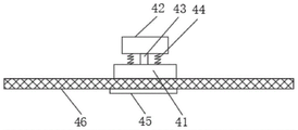
FIG. 4 is a schematic view of an isolation device of an environmentally-friendly circulating wastewater treatment device according to the present invention.
FIG. 5 is a schematic view of an anti-blocking device of an environmentally-friendly circulating wastewater treatment device provided by the utility model.
Illustration of the drawings:
1. a frame body; 2. a filtration device; 3. an anoxic device; 4. an isolation device; 5. an anti-blocking device; 6. a first filter screen; 7. a settling tank; 8. a connecting pipe; 9. a sterilizing box; 10. a water outlet pipe; 11. a water inlet pipe; 21. a filter box; 22. a fixed block; 23. a bearing; 24. a stirring sheet; 25. a stirring rod; 26. a movable rod; 27. a first motor; 28. a second filter screen; 29. a water outlet; 31. an anoxic tank; 32. a first catheter; 33. an air outlet pipe; 34. a fan; 35. a second catheter; 36. a water pump; 37. a third catheter; 41. a connecting plate; 42. a cylinder; 43. connecting columns; 44. a spring; 45. a buffer sheet; 46. an adsorption net; 51. stirring teeth; 52. a stirring rod; 53. a connecting rod; 54. and a second motor.
Detailed Description
The technical solutions in the embodiments of the present invention will be clearly and completely described below with reference to the drawings in the embodiments of the present invention, and it is obvious that the described embodiments are only a part of the embodiments of the present invention, and not all of the embodiments. All other embodiments, which can be derived by a person skilled in the art from the embodiments given herein without making any creative effort, shall fall within the protection scope of the present invention.
In the description of the present invention, it should be noted that the terms "center", "upper", "lower", "left", "right", "vertical", "horizontal", "inner", "outer", etc., indicate orientations or positional relationships based on the orientations or positional relationships shown in the drawings, and are only for convenience of description and simplicity of description, but do not indicate or imply that the device or element being referred to must have a particular orientation, be constructed and operated in a particular orientation, and thus, should not be construed as limiting the present invention; the terms "first," "second," and "third" are used for descriptive purposes only and are not to be construed as indicating or implying relative importance, and furthermore, unless otherwise explicitly stated or limited, the terms "mounted," "connected," and "connected" are to be construed broadly and may be, for example, fixedly connected, detachably connected, or integrally connected; can be mechanically or electrically connected; they may be connected directly or indirectly through intervening media, or they may be interconnected between two elements. The specific meanings of the above terms in the present invention can be understood in specific cases to those skilled in the art.
Referring to fig. 1 to 5, the present invention provides an environmentally friendly circulating wastewater treatment apparatus: including framework 1, framework 1 lateral wall is fixed mounting respectively has inlet tube 11 and outlet pipe 10, 1 inside wall fixed mounting of framework has filter equipment 2, bottom fixed mounting has setting tank 7 in framework 1, top fixed mounting has isolating device 4 in setting tank 7, 7 upper ends fixed mounting of setting tank have connecting pipe 8, 8 lateral wall fixed mounting of connecting pipe has anti-blocking device 5, setting tank 7 passes through connecting pipe 8 fixed connection with filter equipment 2, 7 upper ends fixed mounting of setting tank have oxygen deficiency device 3, top fixed mounting has filter screen 6 in oxygen deficiency device 3 and the framework 1, top fixed mounting has No. one in setting tank 7, 3 fixed mounting of oxygen deficiency device has disinfect box 9, bottom fixed mounting in disinfect box 9 bottom and the framework 1, outlet pipe 10 and 9 lateral wall fixed mounting of disinfect box.
Fixed subassembly includes bearing 23, bearing 23 and movable rod 26 swing joint, and bearing 23 keeps away from the one end fixed mounting of movable rod 26 has fixed block 22, top fixed mounting in fixed block 22 and the rose box 21, and rose box 21 inside wall fixed mounting has No. two filter screens 28, and delivery port 29 has been seted up to rose box 21 bottom, and bearing 23 makes movable rod 26 and movable rod 26 swing joint.
The hypoxia device 3 comprises a hypoxia box 31, an air outlet pipe 33 is fixedly installed at the upper end of the hypoxia box 31, a fan 34 is fixedly installed at one end, far away from the hypoxia box 31, of the air outlet pipe 33, a guide pipe 32 is fixedly installed on one side of the hypoxia box 31, a water pumping assembly is fixedly installed on the other side of the hypoxia box 31, and the air outlet pipe 33 mainly outputs ineffective gas.
The subassembly that draws water includes No. two pipes 35, and No. two pipes 35 keep away from the one end fixed mounting of oxygen deficiency case 31 has No. two pipes 35, and No. two pipes 35 keep away from the one end fixed mounting of water pump 36 has No. three pipes 37, No. three pipes 37 and 7 lateral walls fixed connection of setting tank, and setting tank 7 mainly lets the granule of aquatic deposit.
Isolating device 4 includes connecting plate 41, connecting plate 41 bottom fixed mounting has adsorption net 46, adsorption net 46 lower extreme fixed mounting has buffer piece 45, connecting plate 41 upper end fixed mounting has spliced pole 43, the one end fixed mounting that connecting plate 41 was kept away from to spliced pole 43 has cylinder 42, the outer top fixed connection of cylinder 42 and settling tank 7, connecting plate 41 lower extreme fixed mounting has spring 44, buffer piece 45 mainly plays the cushioning effect, improves adsorption net 46's life.
The working principle is as follows: sewage enters the filtering device 2 through the water inlet pipe 11, the first motor 27 is started to enable the movable rod 26 to drive the stirring sheet 24 to rotate, sewage particles are smashed, the sewage enters the bottom end through the second filter screen 28, enters the connecting pipe 8 through the water outlet 29, starts the second motor 54 to drive the stirring rod 52 and the stirring teeth 51 to rotate, prevents the connecting pipe 8 from being blocked, then sewage enters the settling tank 7, through starting cylinder 42, drive absorption net 46 up-and-down back and forth movement for absorption net 46 adsorbs impurity in the sewage, start water pump 36, enter into No. three pipe 37 and No. two pipe 35 after filtering through filter screen 6 with the water in the setting tank 7 in, finally get into the oxygen deficiency case 31 in, start fan 34, discharge the gas in the oxygen deficiency case 31 by outlet duct 33, the water of handling passes through the oxygen deficiency case 31 and gets into disinfect box 9 in, the back of disinfecting, the water purification is discharged by outlet pipe 10.
Finally, it should be noted that: although the present invention has been described in detail with reference to the foregoing embodiments, it will be apparent to those skilled in the art that modifications may be made to the embodiments or portions thereof without departing from the spirit and scope of the utility model.
Claims (7)
1. The utility model provides an environmental protection endless effluent treatment plant, includes framework (1), its characterized in that: the improved anti-blocking device is characterized in that the side wall of the frame body (1) is respectively fixedly provided with a water inlet pipe (11) and a water outlet pipe (10), the inner side wall of the frame body (1) is fixedly provided with a filtering device (2), the inner bottom of the frame body (1) is fixedly provided with a settling tank (7), the inner top of the settling tank (7) is fixedly provided with an isolating device (4), the upper end of the settling tank (7) is fixedly provided with a connecting pipe (8), the side wall of the connecting pipe (8) is fixedly provided with an anti-blocking device (5), the settling tank (7) is fixedly connected with the filtering device (2) through the connecting pipe (8), the upper end of the settling tank (7) is fixedly provided with an oxygen deficiency device (3), the oxygen deficiency device (3) is fixedly connected with the inner top of the frame body (1), the inner top of the settling tank (7) is fixedly provided with a filter screen (6), and the oxygen deficiency device (3) is fixedly provided with a disinfection box (9), the bottom of the disinfection box (9) is fixedly installed with the bottom of the frame body (1), and the water outlet pipe (10) is fixedly installed with the side wall of the disinfection box (9).
2. The environmentally friendly circulating wastewater treatment plant of claim 1, wherein: filter equipment (2) includes rose box (21), rose box (21) lateral wall fixed mounting has motor (27) No. one, motor (27) output end fixedly connected with movable rod (26), movable rod (26) surface activity cover is equipped with puddler (25), puddler (25) lateral wall fixed mounting has stirring piece (24), movable rod (26) tip swing joint has fixed subassembly.
3. The environmentally friendly circulating wastewater treatment plant of claim 2, wherein: fixed subassembly includes bearing (23), bearing (23) and movable rod (26) swing joint, the one end fixed mounting that movable rod (26) were kept away from in bearing (23) has fixed block (22), fixed block (22) and rose box (21) interior top fixed mounting, rose box (21) inside wall fixed mounting has No. two filter screens (28), delivery port (29) have been seted up to rose box (21) bottom.
4. The environmentally friendly circulating wastewater treatment plant of claim 1, wherein: the oxygen deficiency device (3) includes oxygen deficiency case (31), oxygen deficiency case (31) upper end fixed mounting has outlet duct (33), the one end fixed mounting that oxygen deficiency case (31) were kept away from in outlet duct (33) has fan (34), No. one pipe (32) of oxygen deficiency case (31) one side fixed mounting, oxygen deficiency case (31) opposite side fixed mounting has the subassembly of drawing water.
5. The environmentally friendly circulating wastewater treatment plant of claim 4, wherein: the subassembly of drawing water includes No. two pipe (35), the one end fixed mounting that oxygen deficiency case (31) was kept away from in No. two pipe (35) has No. two pipe (35), the one end fixed mounting that water pump (36) was kept away from in No. two pipe (35) has No. three pipe (37), No. three pipe (37) and setting tank (7) lateral wall fixed connection.
6. The environmentally friendly circulating wastewater treatment plant of claim 1, wherein: isolating device (4) includes connecting plate (41), connecting plate (41) bottom fixed mounting has adsorption net (46), adsorption net (46) lower extreme fixed mounting has buffer sheet (45), connecting plate (41) upper end fixed mounting has spliced pole (43), the one end fixed mounting that connecting plate (41) were kept away from to spliced pole (43) has cylinder (42), the outer top fixed connection of cylinder (42) and setting tank (7), connecting plate (41) lower extreme fixed mounting has spring (44).
7. The environmentally friendly circulating wastewater treatment plant of claim 1, wherein: prevent stifled device (5) including No. two motor (54), No. two motor (54) fixed mounting is on connecting pipe (8) lateral wall, No. two motor (54) output fixed mounting have connecting rod (53), the one end fixed mounting that No. two motor (54) were kept away from in connecting rod (53) has stirring rod (52), stirring rod (52) lateral wall fixed mounting has a plurality of stirring teeth (51).
Priority Applications (1)
| Application Number | Priority Date | Filing Date | Title |
|---|---|---|---|
| CN202122768684.8U CN216584632U (en) | 2021-11-12 | 2021-11-12 | Environment-friendly circulating wastewater treatment device |
Applications Claiming Priority (1)
| Application Number | Priority Date | Filing Date | Title |
|---|---|---|---|
| CN202122768684.8U CN216584632U (en) | 2021-11-12 | 2021-11-12 | Environment-friendly circulating wastewater treatment device |
Publications (1)
| Publication Number | Publication Date |
|---|---|
| CN216584632U true CN216584632U (en) | 2022-05-24 |
Family
ID=81645972
Family Applications (1)
| Application Number | Title | Priority Date | Filing Date |
|---|---|---|---|
| CN202122768684.8U Active CN216584632U (en) | 2021-11-12 | 2021-11-12 | Environment-friendly circulating wastewater treatment device |
Country Status (1)
| Country | Link |
|---|---|
| CN (1) | CN216584632U (en) |
-
2021
- 2021-11-12 CN CN202122768684.8U patent/CN216584632U/en active Active
Similar Documents
| Publication | Publication Date | Title |
|---|---|---|
| CN112573780A (en) | Membrane biological reaction MBR integration sewage treatment system | |
| CN208907065U (en) | A kind of waste water treatment box of sewage treatment | |
| CN212982719U (en) | High-efficient sewage treatment purifies groove | |
| CN211394202U (en) | MBR integration sewage treatment device | |
| CN211946668U (en) | Quick system of buried domestic sewage treatment device | |
| CN216584632U (en) | Environment-friendly circulating wastewater treatment device | |
| CN213623678U (en) | Waste water environmental protection processing apparatus is used in processing of agricultural and livestock products | |
| CN105084601B (en) | River pretreatment unit | |
| CN211111614U (en) | Domestic sewage integration equipment | |
| CN211871727U (en) | High-efficient domestic sewage treatment plant based on MBBR technique | |
| CN211644936U (en) | Culture water treatment system | |
| CN210945183U (en) | Energy-concerving and environment-protective type domestic sewage special treatment device | |
| CN211896363U (en) | Sewage treatment of municipal administration sewage pipe network purifies integrative device | |
| CN211644977U (en) | Membrane biological reaction tank applied to industrial sewage treatment | |
| CN220684887U (en) | Medical sewage treatment equipment | |
| CN213834949U (en) | Utilize sewage treatment system of microbial treatment rural sewage | |
| CN219950735U (en) | Water purification filtering and sterilizing device | |
| CN214880950U (en) | A-M ceramic membrane water purifier | |
| CN214360762U (en) | Domestic sewage filterable recovery unit | |
| CN212102408U (en) | Novel integrated water quality purification treatment device | |
| CN211946687U (en) | Domestic sewage's treatment facility | |
| CN214060205U (en) | Sewage treatment plant is used in gardens that purifying effect is good | |
| CN220745652U (en) | A effluent treatment plant for overware cleaning machine | |
| CN220034205U (en) | Device for purifying and deodorizing sewage by microorganisms | |
| CN215712472U (en) | Small-size integrated medical waste water treatment equipment of social health hospital level |
Legal Events
| Date | Code | Title | Description |
|---|---|---|---|
| GR01 | Patent grant | ||
| GR01 | Patent grant |