CN216550998U - Feeding mechanism for overedger and overedger - Google Patents
Feeding mechanism for overedger and overedger Download PDFInfo
- Publication number
- CN216550998U CN216550998U CN202123143089.1U CN202123143089U CN216550998U CN 216550998 U CN216550998 U CN 216550998U CN 202123143089 U CN202123143089 U CN 202123143089U CN 216550998 U CN216550998 U CN 216550998U
- Authority
- CN
- China
- Prior art keywords
- tooth
- feeding
- differential
- crank
- presser foot
- Prior art date
- Legal status (The legal status is an assumption and is not a legal conclusion. Google has not performed a legal analysis and makes no representation as to the accuracy of the status listed.)
- Active
Links
Images


Landscapes
- Sewing Machines And Sewing (AREA)
Abstract
The utility model discloses a feeding mechanism for an overlock machine and the overlock machine, relating to the technical field of overlock machines, wherein the feeding mechanism comprises a presser foot and a needle plate, the presser foot is connected with a presser foot arm, the presser foot can move up and down relative to the needle plate through the drive of a drive part, the presser foot is provided with a needle slot for accommodating a needle, the needle plate is provided with a first through slot, a lower differential tooth and a lower feeding tooth are arranged in the first through slot, the lower differential tooth and the lower feeding tooth can do translational motion in the first through slot under the drive of a lower tooth drive mechanism, the overlock machine also comprises an upper differential tooth, the upper differential tooth is provided with an upper differential auxiliary tooth, the presser foot is provided with a second through slot, the upper differential tooth and the upper differential auxiliary tooth can do translational motion in the second through slot under the drive of an upper tooth drive mechanism, the upper differential tooth and the lower differential tooth form clamping differential feeding matching, the upper differential auxiliary tooth and the lower feeding tooth form clamping differential feeding matching, the feeding is smooth and flat, and the binding strip cloth is not easy to be sewed.
Description
Technical Field
The utility model relates to the technical field of overedgers, in particular to a feeding mechanism for an overedger and the overedger.
Background
The hemming machine is also called a hemming machine, a stacking machine and a sewing machine, and has the main function of preventing the sewing head of clothes from fluffing through hemming, the feeding mechanism of the existing hemming machine generally comprises a presser foot and a needle plate, a differential tooth and a differential feeding mechanism are arranged below the needle plate, when the hemming machine is used for sewing and hemming binding strips, the feeding of the binding strip cloth is not smooth and uneven, the binding strip cloth can cause wrinkling after sewing, and the edges of the binding strip cloth can be easily separated from sewing during turning.
SUMMERY OF THE UTILITY MODEL
Aiming at the defects of the prior art, the utility model provides a feeding mechanism for a overedger, aiming at solving the problems that the fabric is wrinkled after the binding strip cloth is sewn by the overedger and the edge of the binding strip cloth is easy to be unstitched when the overedger turns.
The technical scheme provided by the utility model is as follows:
the feeding mechanism for the overedger comprises a presser foot and a needle plate, wherein the presser foot is connected with a presser foot arm, the presser foot can move up and down relative to the needle plate under the drive of a driving piece, the presser foot is provided with a needle groove for accommodating a needle, the needle plate is provided with a first through groove, a lower differential tooth and a lower feeding tooth are arranged in the first through groove, the lower differential tooth and the lower feeding tooth can move in a translation mode in the first through groove under the drive of a lower tooth driving mechanism, the overedger further comprises an upper differential tooth, an upper differential auxiliary tooth is arranged on the upper differential tooth, the presser foot is provided with a second through groove, the upper differential tooth and the upper differential auxiliary tooth can move in a translation mode in the second through groove under the drive of the upper tooth driving mechanism, the upper differential tooth and the lower differential tooth form clamping differential feeding matching, and the upper differential auxiliary tooth and the lower feeding tooth form clamping differential feeding matching.
Preferably, a binding strip cloth feeding port is formed in the middle of the presser foot, the binding strip cloth feeding port divides the presser foot into a front end and a rear end according to the cloth advancing direction, the upper differential tooth is arranged at the front end of the presser foot, and the upper differential auxiliary tooth is arranged at the rear end of the presser foot.
Furthermore, the feed inlet of the binding strip cloth is provided with an arc-shaped surface.
The upper differential pair teeth are mounted on the upper differential teeth through screws, sliding grooves are formed in the upper differential pair teeth, and the upper differential pair teeth can move up and down along the sliding grooves when the screws are in a loose state.
The driving piece comprises a driving crank arm and a driving shaft, one end of the driving crank arm is connected with the driving shaft, the other end of the driving crank arm is connected with the presser foot arm, and the driving shaft can drive the driving crank arm to rotate so as to drive the presser foot arm to move up and down through rotation.
The lower tooth driving mechanism comprises a lower differential tooth rack, a lower feeding tooth rack, a feeding crank, a feeding differential crank and a main feeding shaft, wherein the lower differential tooth is in transmission connection with the lower differential tooth rack and the feeding differential crank in sequence, the lower feeding tooth is in transmission connection with the lower feeding tooth rack and the feeding crank in sequence, and the feeding crank and the feeding differential crank are sleeved on the main feeding shaft.
The upper tooth driving mechanism comprises an upper feeding tooth rack, an upper cloth feeding shaft, an upper cloth feeding crank assembly, an upper cloth feeding connecting rod and a main shaft, the upper differential tooth is sequentially in transmission connection with the upper feeding tooth rack and the upper cloth feeding shaft, the upper cloth feeding crank assembly comprises a first crank and a second crank, the first crank is sleeved on the upper cloth feeding shaft, the second crank is in transmission connection with the first crank and the upper cloth feeding connecting rod respectively, and the upper cloth feeding connecting rod is sleeved on the main shaft.
The utility model also provides an overlock machine which comprises the feeding mechanism for the overlock machine.
The utility model has the beneficial effects that: the utility model ensures the flatness of the binding strip cloth in the sewing process through the differential and comprehensive feeding of the two groups of upper and lower teeth, so that the feeding of the binding strip cloth is smoother and smoother, the edge seam of the binding strip cloth can not be removed in the turning process, and the quality and the production efficiency of products are improved.
Drawings
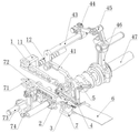
Fig. 1 is a schematic perspective view of a feeding mechanism according to the present invention.
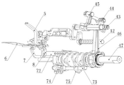
Fig. 2 is a schematic perspective view of another angle of the feeding mechanism of the present invention.
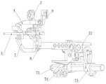
Fig. 3 is a schematic perspective view of a partial structure of the feeding mechanism of the present invention.
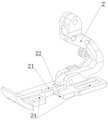
Fig. 4 is a schematic structural view of a presser foot of the feeding mechanism of the present invention.
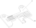
Fig. 5 is a schematic structural view of a needle plate of the feed mechanism of the present invention.
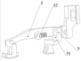
Fig. 6 is an exploded view of the upper differential tooth and the upper differential auxiliary tooth of the feeding mechanism of the present invention.
Fig. 7 is a schematic structural view of a lower differential tooth and a lower feed tooth of the feed mechanism of the present invention.
FIG. 8 is a schematic structural view of the overlock machine of the present invention.
Detailed Description
The embodiments of the present invention will be further described with reference to the accompanying drawings.
As shown in fig. 1-7, a feeding mechanism for an overlock machine comprises a presser foot 2 and a needle plate 3, wherein the presser foot 2 is connected with a presser foot arm 1, the presser foot 2 can move up and down relative to the needle plate 3 through the driving of a driving part, the driving part comprises a driving crank arm 11 and a driving shaft 12, one end of the driving crank arm 11 is connected with the driving shaft 12, the other end of the driving crank arm is connected with the presser foot arm 1, and the driving shaft 12 can drive the driving crank arm 11 to rotate so as to drive the presser foot arm 1 to move up and down.
The presser foot 2 is provided with a needle groove 21 for accommodating a needle, the needle plate 3 is provided with a first through groove 31, a lower differential tooth 7 and a lower feeding tooth 8 are arranged in the first through groove 31, the lower differential tooth 7 and the lower feeding tooth 8 can move in the first through groove 31 in a translation mode under the driving of a lower tooth driving mechanism, the lower tooth driving mechanism comprises a lower differential tooth frame 71, a lower feeding tooth frame 72, a feeding crank 75, a feeding differential crank 74 and a main feeding shaft 73, the lower differential tooth 7 is sequentially in transmission connection with the lower differential tooth frame 71 and the feeding differential crank 74, the lower feeding tooth 8 is sequentially in transmission connection with the lower feeding tooth frame 72 and the feeding crank 75, and the feeding crank 75 and the feeding differential crank 74 are sleeved on the main feeding shaft 73. The main feeding shaft 73 can drive the feeding crank 75 and the feeding differential crank 74 to rotate so as to drive the lower differential rack 71 and the lower feeding rack 72 to do translational motion, and due to the fact that the rotating paths of the feeding crank 75 and the feeding differential crank 74 are different, the translational speeds of the lower differential rack 71 and the lower feeding rack 72 are different, and differential feeding is achieved.
In this embodiment, the differential tooth fixing device further comprises an upper differential tooth 4, an upper differential auxiliary tooth 9 is arranged on the upper differential tooth 4, the upper differential auxiliary tooth 9 is mounted on the upper differential tooth 4 through a screw 42, the upper differential auxiliary tooth 9 is provided with a sliding groove 91, the upper differential auxiliary tooth 9 can move up and down along the sliding groove when the screw 42 is in a loose state, and the screw 42 can be screwed down to complete fixing when the screw 42 moves to a specified position. The presser foot is provided with a second through groove 24, the upper differential tooth 4 and the upper differential auxiliary tooth 9 can perform translational motion in the second through groove 24 under the driving of an upper tooth driving mechanism, the upper tooth driving mechanism comprises an upper feeding tooth rack 41, an upper cloth feeding shaft 43, an upper cloth feeding crank assembly, an upper cloth feeding connecting rod 46 and a main shaft 47, the upper differential tooth 4 is sequentially in transmission connection with the upper feeding tooth rack 41 and the upper cloth feeding shaft 43, the upper cloth feeding crank assembly comprises a first crank 44 and a second crank 45, the first crank 44 is sleeved on the upper cloth feeding shaft 43, the second crank 45 is respectively in transmission connection with the first crank 44 and the upper cloth feeding connecting rod 46, and the upper cloth feeding connecting rod 46 is sleeved on the main shaft 47.
The upper differential tooth 4 and the lower differential tooth 7 form clamping differential feeding matching, and the upper differential auxiliary tooth 9 and the lower feeding tooth 8 form clamping differential feeding matching. The clamping differential feeding matching means that two groups of teeth are clamped mutually, and the translation speeds are inconsistent through the upper tooth driving mechanism and the lower tooth driving mechanism, so that differential feeding is realized.
In this embodiment, the middle of the presser foot 2 is provided with a binding strip cloth feeding port 22, and the binding strip cloth feeding port 22 is provided with an arc-shaped surface for feeding. The binding strip cloth feed port 22 divides the presser foot into a front end and a rear end according to the cloth advancing direction, the upper differential tooth 4 is arranged at the front end of the presser foot 2, and the upper differential auxiliary tooth 9 is arranged at the rear end of the presser foot. During feeding, the cloth 6 is fed from the front end of the presser foot 2, and the binding strip cloth 5 is fed from the binding strip cloth feed port 22 in the middle of the presser foot 2, so that the feeding is smoother and smoother.
As shown in fig. 8, the overedger comprises a shell 101 and a needle plate seat 102, wherein the feeding mechanism for the overedger is characterized in that a needle plate 2 of the feeding mechanism is arranged on the needle plate seat 102, and the flatness of the binding strip cloth in the sewing process is ensured through differential comprehensive feeding by compressing two groups of upper teeth and lower teeth, so that the feeding of the binding strip 5 is smoother, the edge seam of the binding strip cloth can not be removed in the turning process, and the quality and the production efficiency of products are improved.
The examples should not be construed as limiting the utility model, and any non-inventive modifications made based on the spirit of the utility model should be construed as being within the scope of the utility model.
Claims (8)
1. A feeding mechanism for overedger, including presser foot (2), faller (3), presser foot (2) link to each other with presser foot arm (1), presser foot (2) can be for faller (3) up-and-down motion through the driving piece drive, presser foot (2) have the eedle groove (21) of holding eedle, faller (3) are equipped with first logical groove (31), be equipped with down differential tooth (7) and lower pay-off tooth (8) in first logical groove (31), down differential tooth (7) and pay-off tooth (8) can make translational motion in first logical groove (31) under tooth actuating mechanism's drive down, its characterized in that: the upper differential tooth (4) is provided with an upper differential auxiliary tooth (9), the presser foot (2) is provided with a second through groove (24), the upper differential tooth (4) and the upper differential auxiliary tooth (9) can perform translational motion in the second through groove (24) under the driving of an upper tooth driving mechanism, the upper differential tooth (4) and the lower differential tooth (7) form clamping differential feeding matching, and the upper differential auxiliary tooth (9) and the lower feeding tooth (8) form clamping differential feeding matching.
2. The feed mechanism for an overlock machine as claimed in claim 1, wherein: the cloth pressing device is characterized in that a binding strip cloth feeding hole (22) is formed in the middle of the pressing foot (2), the binding strip cloth feeding hole (22) divides the pressing foot (2) into a front end and a rear end according to the cloth advancing direction, the upper differential tooth (4) is arranged at the front end of the pressing foot, and the upper differential auxiliary tooth (9) is arranged at the rear end of the pressing foot.
3. The feed mechanism for an overlock machine as claimed in claim 2, wherein: the binding strip cloth feeding hole (22) is provided with an arc-shaped surface.
4. The feed mechanism for an overlock machine as claimed in claim 1, wherein: the upper differential auxiliary tooth (9) is mounted on the upper differential tooth (4) through a screw (42), the upper differential auxiliary tooth (9) is provided with a sliding groove (91), and the upper differential auxiliary tooth (9) can move up and down along the sliding groove (91) when the screw (42) is in a loose state.
5. The feed mechanism for an overlock machine as claimed in claim 1, wherein: the driving piece comprises a driving crank arm (11) and a driving shaft (12), one end of the driving crank arm (11) is connected with the driving shaft (12), the other end of the driving crank arm is connected with the presser foot arm (1), and the driving shaft (12) can drive the driving crank arm (11) to rotate so as to drive the presser foot arm (1) to move up and down.
6. The feed mechanism for an overlock machine as claimed in claim 1, wherein: the lower tooth driving mechanism comprises a lower differential tooth rack (71), a lower feeding tooth rack (72), a feeding crank (75), a feeding differential crank (74) and a main feeding shaft (73), the lower differential tooth (7) is sequentially in transmission connection with the lower differential tooth rack (71) and the feeding differential crank (74), the lower feeding tooth (8) is sequentially in transmission connection with the lower feeding tooth rack (72) and the feeding crank (75), and the feeding crank (75) and the feeding differential crank (74) are sleeved on the main feeding shaft (73).
7. The feed mechanism for an overlock machine as claimed in claim 1, wherein: the upper tooth driving mechanism comprises an upper feeding tooth frame (41), an upper cloth feeding shaft (43), an upper cloth feeding crank assembly, an upper cloth feeding connecting rod (46) and a main shaft (47), the upper differential tooth (4) is sequentially in transmission connection with the upper feeding tooth frame (41) and the upper cloth feeding shaft (43), the upper cloth feeding crank assembly comprises a first crank (44) and a second crank (45), the upper cloth feeding shaft (43) is sleeved with the first crank (44), the second crank (45) is in transmission connection with the first crank (44) and the upper cloth feeding connecting rod (46) respectively, and the upper cloth feeding connecting rod (46) is sleeved on the main shaft (47).
8. An overlock machine, characterized in that: comprising a feed mechanism for an overlock machine as claimed in any one of claims 1 to 7.
Priority Applications (1)
| Application Number | Priority Date | Filing Date | Title |
|---|---|---|---|
| CN202123143089.1U CN216550998U (en) | 2021-12-15 | 2021-12-15 | Feeding mechanism for overedger and overedger |
Applications Claiming Priority (1)
| Application Number | Priority Date | Filing Date | Title |
|---|---|---|---|
| CN202123143089.1U CN216550998U (en) | 2021-12-15 | 2021-12-15 | Feeding mechanism for overedger and overedger |
Publications (1)
| Publication Number | Publication Date |
|---|---|
| CN216550998U true CN216550998U (en) | 2022-05-17 |
Family
ID=81542392
Family Applications (1)
| Application Number | Title | Priority Date | Filing Date |
|---|---|---|---|
| CN202123143089.1U Active CN216550998U (en) | 2021-12-15 | 2021-12-15 | Feeding mechanism for overedger and overedger |
Country Status (1)
| Country | Link |
|---|---|
| CN (1) | CN216550998U (en) |
-
2021
- 2021-12-15 CN CN202123143089.1U patent/CN216550998U/en active Active
Similar Documents
| Publication | Publication Date | Title |
|---|---|---|
| CN210975088U (en) | Cloth pressing device of sewing machine | |
| CN216550998U (en) | Feeding mechanism for overedger and overedger | |
| CN214244829U (en) | Cloth clamping mechanism of automatic flanging device for front trouser pocket welting sewing | |
| CN219079800U (en) | Thick material flush joint machine | |
| CN110130011B (en) | Upper-folded non-ironing slotting composite pull cylinder | |
| CN213061282U (en) | Special edge-covering sewing transmission structure for zigzag sewing machine | |
| CN216427575U (en) | 3D screen cloth sewing machine that bordures | |
| CN212895306U (en) | Double-needle synchronous adhesive tape sewing machine | |
| CN218580235U (en) | Handle sewing device for handle serging machine | |
| CN216998831U (en) | Novel front trouser pocket welt sewing device | |
| CN214300655U (en) | Sewing device | |
| CN218711348U (en) | Auxiliary clamping mechanism of sewing machine | |
| CN214244824U (en) | Automatic flanging device for front trouser pocket welting and sewing | |
| CN218711327U (en) | Double-needle flat-seam sewing machine for making non-woven fabric bag | |
| CN210481707U (en) | Needle plate assembly of double-thread arching stitch of flat seaming machine | |
| CN103643408A (en) | Fabric hemming and stitching device | |
| CN216585519U (en) | Jeans thick line sewing equipment | |
| CN217948454U (en) | Double-needle sewing edge-covering sewing pull cylinder | |
| CN215829034U (en) | Automatic hemming and sewing mechanism of hemming machine | |
| CN218466093U (en) | Sewing thread take-up mechanism with compact structure and sewing machine | |
| CN217757906U (en) | Overedger | |
| CN112411039B (en) | Three-dimensional enhanced fold embroidery forming mechanism | |
| CN216688597U (en) | Supplementary device of tailorring of down coat processing sewing machine | |
| CN210826629U (en) | Side-splicing double-purlin edge presser foot | |
| CN214938291U (en) | Cloth feeding system |
Legal Events
| Date | Code | Title | Description |
|---|---|---|---|
| GR01 | Patent grant | ||
| GR01 | Patent grant |