CN216534810U - Improved quantitative drinking cup - Google Patents
Improved quantitative drinking cup Download PDFInfo
- Publication number
- CN216534810U CN216534810U CN202123265569.5U CN202123265569U CN216534810U CN 216534810 U CN216534810 U CN 216534810U CN 202123265569 U CN202123265569 U CN 202123265569U CN 216534810 U CN216534810 U CN 216534810U
- Authority
- CN
- China
- Prior art keywords
- cup
- quantitative
- water
- water storage
- drinking
- Prior art date
- Legal status (The legal status is an assumption and is not a legal conclusion. Google has not performed a legal analysis and makes no representation as to the accuracy of the status listed.)
- Active
Links
Images



Landscapes
- Medical Preparation Storing Or Oral Administration Devices (AREA)
Abstract
The utility model discloses an improved quantitative water drinking cup, which comprises a water storage cup, a quantitative water suction mechanism, a quantitative cup and a cup mouth, wherein the water storage cup is arranged on the upper part of the water storage cup; the top of the water storage cup is detachably and hermetically connected with the bottom of the quantitative water absorption mechanism, and the top of the quantitative water absorption mechanism is fixedly connected with the bottom of the quantitative cup; the quantitative water sucking mechanism is provided with a water sucking pipe and a water outlet pipe, the water sucking pipe extends to the bottom of the water storage cup, the water outlet pipe extends into the quantitative cup, and the quantitative water sucking mechanism sucks water from the water storage cup and supplies the water to the quantitative cup; the quantitative cup is made of transparent materials, and the peripheral wall of the quantitative cup is provided with volume scales; the cup mouth is detachably connected with the top of the quantitative cup. The water storage cup can suck quantitative water from the water storage cup into the quantitative cup at the top every time, so that a bedridden heart failure patient can drink and record the water, the workload of accompanying and attending is reduced, and the risk of heart failure caused by excessive drinking of the patient is reduced.
Description
Technical Field
The utility model relates to the technical field of medical equipment, in particular to an improved quantitative drinking cup.
Background
Chronic heart failure is one of the common cardiovascular diseases in clinic, is better developed for the elderly, and is the final outcome of most cardiovascular diseases in clinic. Heart failure, or heart failure, is a group of clinical syndromes caused by ventricular filling and/or hypofunction of ejection due to various structural or functional abnormalities of the heart. The main manifestations are dyspnea, fatigue and fluid retention. Water-limited treatment is used as an important component of clinical care and self-care of heart failure patients, and accurate recording of the amount of the entering and exiting is the most basic clinical care work. The input is mainly diet, drinking water and transfusion, and the accurate record of the method has key influence on the doctor to make and adjust the diagnosis and treatment scheme. The existing drinking cup has no display of small quantitative scales, and the water intake of a patient cannot be accurately calculated. Some old people forget to drink water; after the individual patient uses the diuretic, the patient feels thirsty obviously and the drinking amount is not increased voluntarily, but the patient and the accompanying person cannot record the thirst accurately every time the patient uses a small mouth or a small spoon. Many attendants are difficult to calculate or cannot accompany and register for a long time clinically, and the water intake is estimated approximately at many times, so that the intake record is inaccurate, interference is caused for doctors to make and adjust diagnosis and treatment schemes, and the rehabilitation of patients is influenced.
Disclosure of Invention
The utility model provides an improved quantitative water drinking cup which can suck quantitative water from a water storage cup into a quantitative cup at the top every time, so that a bedridden heart failure patient can drink and record the water by himself, the workload of accompanying and attending is reduced, and the risk of heart failure caused by excessive drinking of the patient is reduced.
In order to achieve the purpose, the utility model adopts the technical scheme that:
an improved quantitative drinking cup comprises a water storage cup, a quantitative water suction mechanism, a quantitative cup and a cup mouth; the top of the water storage cup is detachably and hermetically connected with the bottom of the quantitative water absorption mechanism, and the top of the quantitative water absorption mechanism is fixedly connected with the bottom of the quantitative cup; the quantitative water sucking mechanism is provided with a water sucking pipe and a water outlet pipe, the water sucking pipe extends to the bottom of the water storage cup, the water outlet pipe extends into the quantitative cup, and the quantitative water sucking mechanism sucks water from the water storage cup and supplies the water to the quantitative cup; the quantitative cup is made of transparent materials, and the peripheral wall of the quantitative cup is provided with volume scales; the cup mouth is detachably connected with the top of the quantitative cup.
Further, the quantitative water absorption mechanism comprises a mounting shell and a pressing pump body; the installation shell is internally provided with a cavity structure, the pressing pump body is installed in the installation shell, and the water suction pipe and the water outlet pipe are connected to the pressing pump body; the bottom of the mounting shell is hermetically connected with the water storage cup; the top of the mounting shell is fixedly connected with the quantifying cup; the pressing head of the pressing pump body extends out of the mounting shell.
Further, the bottom of the mounting shell is in threaded connection with the water storage cup, and the top of the mounting shell and the top of the water storage cup are sealed by a sealing ring.
Furthermore, two sides of the mounting shell are respectively provided with a force application boss.
Further, the improved quantitative drinking cup further comprises a protective rubber sleeve; the protective rubber sleeve is sleeved on the periphery of the water storage cup, and two handles are arranged on two sides of the protective rubber sleeve respectively.
Furthermore, the cup mouth comprises a cup cover and a suction pipe, the cup cover is in threaded connection with the top of the quantifying cup, the cup cover is provided with a through hole, the suction pipe enters the quantifying cup from the through hole, and a gravity ball is arranged at one end of the suction pipe, which is located in the quantifying cup.
Further, the cup mouth comprises a cup cover and a liquid food joint; the cup cover is in threaded connection with the top of the quantifying cup, the liquid food connector is fixedly connected to the cup cover, and the liquid food connector is communicated into the quantifying cup.
The utility model has the beneficial effects that:
quantitative drinking water mechanism absorbs quantitative water from the retaining cup at every turn and gets into in the quantitative cup at top, volume scale through the periphery wall, can accurate record low dose water intake, make things convenient for the nurse to carry out the healthy propaganda and education of pertinence post-operative nursing, improve the compliance of healthy propaganda and education, make things convenient for bed heart failure patient to drink water and record by oneself, reduce the work load of accompanying and attending to, improve clinical work efficiency, make for the doctor, the adjustment is diagnose the scheme and is provided powerful evidence, more be favorable to patient's recovery, and the personal diet nursing at home of patient after the discharge, reduce the patient because the drinking water excess leads to the risk of heart failure, also reduce the work load that the family was attended to after the patient was discharged.
Drawings
The following detailed description of embodiments of the utility model is provided in conjunction with the appended drawings, in which:
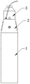
FIG. 1 is a perspective view of the present invention;
FIG. 2 is a schematic rear view of the present invention;
FIG. 3 is a schematic structural view of a first embodiment of a nozzle according to the present invention;
FIG. 4 is a schematic structural view of a second embodiment of the nozzle of the present invention;
the attached drawings are as follows:
1-water storage cup, 2-quantitative water absorption mechanism, 3-quantitative cup, 4-cup mouth, 5-protective rubber sleeve, 21-installation shell, 22-pressing pump body, 23-water absorption pipe, 24-water outlet pipe, 31-volume scale, 41-cup cover, 42-suction pipe, 43-gravity ball, and 44-liquid diet joint.
Detailed Description
The technical solutions in the embodiments of the present invention will be clearly and completely described below with reference to the drawings in the embodiments of the present invention, and it is obvious that the described embodiments are only a part of the embodiments of the present invention, and not all of the embodiments. All other embodiments, which can be derived by a person skilled in the art from the embodiments given herein without making any creative effort, shall fall within the protection scope of the present invention.
It will be understood that when an element is referred to as being "secured to" another element, it can be directly on the other element or intervening elements may also be present. When a component is referred to as being "connected" to another component, it can be directly connected to the other component or intervening components may also be present. When a component is referred to as being "disposed on" another component, it can be directly on the other component or there can be intervening components, and when a component is referred to as being "disposed in the middle," it is not just disposed in the middle, so long as it is not disposed at both ends, but rather is within the scope of the middle. The terms "vertical," "horizontal," "left," "right," and the like as used herein are for illustrative purposes only.
Unless defined otherwise, all technical and scientific terms used herein have the same meaning as commonly understood by one of ordinary skill in the art to which this invention belongs. The terminology used in the description of the utility model herein is for the purpose of describing particular embodiments only and is not intended to be limiting of the utility model. As used herein, the term "and/or" includes any and all combinations of one or more of the associated listed items.
Referring to fig. 1 to 4, an improved quantitative drinking cup comprises a water storage cup 1, a quantitative water absorption mechanism 2, a quantitative cup 3 and a cup mouth 4; the top of the water storage cup 1 is detachably and hermetically connected with the bottom of the quantitative water absorption mechanism 2, and the top of the quantitative water absorption mechanism 2 is fixedly connected with the bottom of the quantitative cup 3; the quantitative water absorption mechanism 2 is provided with a water absorption pipe 23 and a water outlet pipe 24, the water absorption pipe 23 extends to the bottom of the water storage cup 1, the water outlet pipe 24 extends into the quantitative cup 3, and the quantitative water absorption mechanism 2 absorbs water from the water storage cup 1 and supplies the water to the quantitative cup 3; the quantitative cup 3 is made of transparent materials, and the peripheral wall of the quantitative cup 3 is provided with volume scales 31; the cup mouth 4 is detachably connected with the top of the quantitative cup 3. Specifically, the water storage cup 1 is designed to be cylindrical, the water storage cup 1 and the quantitative water absorption mechanism 2 are detachably and hermetically connected to form a water storage cavity, and water can be conveniently disassembled and filled due to the detachable design; retaining cup 1, the ration mechanism of absorbing water 2, ration cup 3 is arranged from supreme down in proper order, ration drinking water mechanism 2 absorbs quantitative water from retaining cup 1 at every turn and gets into in the ration cup 3 at top, volume scale 31 through the periphery wall, can accurate record small dose drinking water volume, make things convenient for the nurse to carry out the healthy propaganda and education of pertinence postoperative care, improve the compliance of healthy propaganda and education, make things convenient for the heart failure patient of lying in bed to drink water and record by oneself, reduce the work load of accompanying and attending to, improve clinical work efficiency, for the doctor makes, adjustment diagnosis and treatment scheme provides strong evidence, more be favorable to patient's recovery, and the individual diet nursing at home of the back patient of leaving the hospital, reduce the patient because the incidence of drinking water excessive heart failure, also for the work load that reduces family care after the patient leaves the hospital.
The quantitative water absorption mechanism 2 comprises a mounting shell 21 and a pressing pump body 22; a cavity structure is arranged in the mounting shell 21, the pressing pump body 22 is mounted in the mounting shell 21, and the water suction pipe 23 and the water outlet pipe 24 are both connected to the pressing pump body 22; the bottom of the mounting shell 21 is hermetically connected with the water storage cup 1; the top of the mounting shell 21 is fixedly connected with the quantifying cup 3; the pressing head of the pressing pump body 22 extends to the outside of the mounting case 21. The bottom of the mounting shell 21 is in threaded connection with the water storage cup 1, and the mounting shell 21 and the top of the water storage cup 1 are sealed by a sealing ring. Two sides of the mounting housing 21 are respectively provided with a force applying boss 221. The improved quantitative drinking cup further comprises a protective rubber sleeve 5; the protective rubber sleeve 5 is sleeved on the periphery of the water storage cup 1, and two handles 51 are respectively arranged on two sides of the protective rubber sleeve 5. Specifically, the mounting housing 21 is made of a hard plastic material; the water storage cup 1 and the quantitative cup 3 are both made of high borosilicate glass materials; the pressing pump body 22 adopts a conventional small pressing pump, and the pipeline arrangement can be adaptively changed according to the actual situation during manufacturing; the protection gum cover 5 adopts silica gel material, and the handle 51 makes things convenient for the bed patient to hold by oneself and takes, and whole protection gum cover 5 prevents scalding with the parcel of retaining cup 1, and protection gum cover 5 also plays the antiskid effect moreover, and the application of force boss 221 on the cooperation installation casing 21 facilitates the user and unscrews installation casing 21, opens the retaining cup. During the use, the user passes through the press head of pressing pump body 22 and in drainage to ration cup 3 with the water in the retaining cup 1, carries the water yield of quota according to the doctor's advice. In order to increase the sealing performance, the water suction pipe 23, the water outlet pipe 24 and the mounting shell 21 are directly sealed by rubber rings.
The first embodiment of the cup mouth:
referring to fig. 3, the nozzle 4 includes a cup cover 41 and a suction pipe 42, the cup cover 41 is in threaded connection with the top of the dosing cup 3, the cup cover 41 is provided with a through hole, the suction pipe enters the dosing cup from the through hole, and one end of the suction pipe located in the dosing cup is provided with a gravity ball 43. The patient sucks the water in the measuring cup 3 through the suction tube 42, and the gravity ball 43 allows the end of the suction tube to sink to the bottom of the measuring cup 3. Correspondingly, the measuring range of the volume scale 31 needs to be finely adjusted according to the shapes of the suction pipe and the gravity ball.
Embodiment two of the cup mouth:
referring to fig. 4, the cup mouth 4 includes a cup lid 41 and a feeding joint 44; the cup cover 41 is in threaded connection with the top of the dosing cup 3, the liquid food connector 44 is fixedly connected to the cup cover 41, and the liquid food connector 44 is communicated into the dosing cup 3. The present invention can also be used to dose liquid foods via the liquid food connector 44.
The above embodiments are only for illustrating the technical solutions of the present invention and are not limited thereto, and any modification or equivalent replacement without departing from the spirit and scope of the present invention should be covered within the technical solutions of the present invention.
Claims (7)
1. An improved quantitative drinking cup is characterized by comprising a water storage cup, a quantitative water sucking mechanism, a quantitative cup and a cup mouth; the top of the water storage cup is detachably and hermetically connected with the bottom of the quantitative water absorption mechanism, and the top of the quantitative water absorption mechanism is fixedly connected with the bottom of the quantitative cup; the quantitative water sucking mechanism is provided with a water sucking pipe and a water outlet pipe, the water sucking pipe extends to the bottom of the water storage cup, the water outlet pipe extends into the quantitative cup, and the quantitative water sucking mechanism sucks water from the water storage cup and supplies the water to the quantitative cup; the quantitative cup is made of transparent materials, and the peripheral wall of the quantitative cup is provided with volume scales; the cup mouth is detachably connected with the top of the quantitative cup.
2. The improved quantitative drinking cup as claimed in claim 1, wherein the quantitative water sucking mechanism comprises a mounting housing and a pressing pump body; the installation shell is internally provided with a cavity structure, the pressing pump body is installed in the installation shell, and the water suction pipe and the water outlet pipe are connected to the pressing pump body; the bottom of the mounting shell is hermetically connected with the water storage cup; the top of the mounting shell is fixedly connected with the quantifying cup; the pressing head of the pressing pump body extends out of the mounting shell.
3. The improved quantitative drinking cup as claimed in claim 2, wherein the bottom of the mounting housing is screwed to the water cup, and the mounting housing is sealed with the top of the water cup by a sealing ring.
4. The improved quantitative drinking cup as claimed in claim 3, wherein the mounting housing has a force applying boss at each side.
5. The improved quantitative drinking cup as claimed in claim 3, further comprising a protective rubber sleeve; the protective rubber sleeve is sleeved on the periphery of the water storage cup, and two handles are arranged on two sides of the protective rubber sleeve respectively.
6. The improved quantitative drinking cup as claimed in claim 1, wherein the mouth includes a lid and a suction tube, the lid is screwed to the top of the quantitative cup, the lid has a through hole, the suction tube enters the quantitative cup through the through hole, and a gravity ball is disposed at an end of the suction tube inside the quantitative cup.
7. The improved quantitative drinking cup as set forth in claim 1, wherein the mouth includes a lid and a drinking nipple; the cup cover is in threaded connection with the top of the quantifying cup, the liquid food connector is fixedly connected to the cup cover, and the liquid food connector is communicated into the quantifying cup.
Priority Applications (1)
| Application Number | Priority Date | Filing Date | Title |
|---|---|---|---|
| CN202123265569.5U CN216534810U (en) | 2021-12-23 | 2021-12-23 | Improved quantitative drinking cup |
Applications Claiming Priority (1)
| Application Number | Priority Date | Filing Date | Title |
|---|---|---|---|
| CN202123265569.5U CN216534810U (en) | 2021-12-23 | 2021-12-23 | Improved quantitative drinking cup |
Publications (1)
| Publication Number | Publication Date |
|---|---|
| CN216534810U true CN216534810U (en) | 2022-05-17 |
Family
ID=81555892
Family Applications (1)
| Application Number | Title | Priority Date | Filing Date |
|---|---|---|---|
| CN202123265569.5U Active CN216534810U (en) | 2021-12-23 | 2021-12-23 | Improved quantitative drinking cup |
Country Status (1)
| Country | Link |
|---|---|
| CN (1) | CN216534810U (en) |
-
2021
- 2021-12-23 CN CN202123265569.5U patent/CN216534810U/en active Active
Similar Documents
| Publication | Publication Date | Title |
|---|---|---|
| WO2018053045A2 (en) | Breast sense feeding monitor | |
| CN105768777A (en) | Intelligent old-people healthy-water-drinking monitoring system | |
| CN216534810U (en) | Improved quantitative drinking cup | |
| CN203468831U (en) | Urine collector for women | |
| CN206896475U (en) | A kind of unisex type sickbed patients multifunctional urine or excrement receiving device | |
| CN210870898U (en) | Swallowing disorder patient feeds a cup with liquid food | |
| CN208834532U (en) | A kind of hemodialysis catheter nursing brand teaching aid | |
| CN208641117U (en) | Woman urine acceptor and nursing system | |
| CN208372069U (en) | It is a kind of can Precise collection urine Portable medical chamber pot | |
| CN208710339U (en) | A kind of medical woman style bedpan facilitating metering urine | |
| CN220236572U (en) | Anti-choking metering multifunctional drinking cup | |
| CN209436741U (en) | A kind of head auxiliary drop panel for baby | |
| CN213911008U (en) | Portable universal bed urinal | |
| CN213371177U (en) | Quantity-controlled tableware capable of displaying temperature | |
| CN218010467U (en) | Neonate nurses and uses urine ration collection system | |
| CN215938339U (en) | Vomitus collecting device with oral cavity flushing function | |
| CN220344760U (en) | Medicine feeding and feeding nursing device | |
| CN220459102U (en) | Quantitative drinking cup for heart failure patient | |
| CN214713463U (en) | Special medicine taking metering cup for department of pediatrics | |
| CN214596519U (en) | Thoracic cardiac surgery nursing is with children's medicine feed device | |
| CN216652991U (en) | Drainage bottle convenient to measurement monitoring | |
| CN215022563U (en) | Swallowing disorder patient feeds a cup with liquid food | |
| CN212995872U (en) | Intelligent cup for measuring liquid intake | |
| CN203183338U (en) | Drinking cup for bedridden patient | |
| CN210963095U (en) | Heavily sick patient is with device of dosing |
Legal Events
| Date | Code | Title | Description |
|---|---|---|---|
| GR01 | Patent grant | ||
| GR01 | Patent grant |