CN216526907U - Temperature controller with protection function - Google Patents
Temperature controller with protection function Download PDFInfo
- Publication number
- CN216526907U CN216526907U CN202122743235.8U CN202122743235U CN216526907U CN 216526907 U CN216526907 U CN 216526907U CN 202122743235 U CN202122743235 U CN 202122743235U CN 216526907 U CN216526907 U CN 216526907U
- Authority
- CN
- China
- Prior art keywords
- connecting rod
- magnet
- spring
- iron
- wall
- Prior art date
- Legal status (The legal status is an assumption and is not a legal conclusion. Google has not performed a legal analysis and makes no representation as to the accuracy of the status listed.)
- Active
Links
Images


Landscapes
- Casings For Electric Apparatus (AREA)
Abstract
The utility model relates to the technical field of temperature controllers, and discloses a temperature controller with a protection function, which comprises a temperature controller body and a using device, wherein the using device comprises a mounting box, a first magnet strip, a metal frame transparent cover, a rotating shaft, a hand-held block, a first connecting rod, a sliding block, a spring, a folding type blocking cloth, a second connecting rod, a first iron-absorbing stone and a second iron-absorbing stone, the first connecting rod, the sliding block, the spring, the folding type blocking cloth, the second connecting rod, the first iron-absorbing stone and the second iron-absorbing stone are arranged, the folding type blocking cloth has a certain folding function by pulling the second connecting rod, when the second connecting rod is completely pulled, the first iron-absorbing stone and the second iron-absorbing stone are attracted to protect, wherein the spring has certain elasticity by using the spring, when the first iron-absorbing stone and the second iron-absorbing stone are separated from the attraction state, the spring rebounds, folding type blocking cloth can be conveniently and rapidly folded, and the effect of convenience is achieved.
Description
Technical Field
The utility model relates to the technical field of temperature controllers, in particular to a temperature controller with a protection function.
Background
The temperature controller is a series of automatic control elements which are physically deformed in a switch according to the temperature change of a working environment so as to generate certain special effects and generate on or off actions, and is also called a temperature control switch, a temperature protector and a temperature controller, the temperature controller is called the temperature controller for short, or the temperature is transmitted to the temperature controller through the temperature protector, the temperature controller sends a switch command, so that the operation of equipment is controlled to achieve ideal temperature and energy-saving effects, the application range of the temperature controller is very wide, and the temperature controller is applied to various products such as household appliances, motors, refrigeration or heating and the like according to different types of temperature controllers.
The existing temperature controller does not have a protection function, and a display screen of the temperature controller is easy to damage and scratch due to impact of external force, so that the service life is shortened.
SUMMERY OF THE UTILITY MODEL
The utility model aims to provide a temperature controller with a protection function, and the purpose of convenient use is achieved.
In order to achieve the purpose, the utility model provides the following technical scheme: the utility model provides a temperature controller that possesses safeguard function, includes temperature controller body and operative installations, operative installations is including mounting box, first magnet strip, metal frame translucent cover, axis of rotation, portable piece, first connecting rod, slider, spring, foldable fender cloth, second connecting rod, first magnet and second magnet, temperature controller body sets up in the mounting box, inner wall one side and the setting of first magnet strip of mounting box, the inner wall one side rotation of metal frame translucent cover through axis of rotation and mounting box is connected, the sliding tray has been seted up to the mounting box.
Preferably, the front face of the metal frame transparent cover is fixedly connected with the portable block, and the metal frame transparent cover is convenient to turn over by using the portable block.
Preferably, one side of the back surface of the metal frame transparent cover is attracted with the first magnet strip, and the first magnet strip and the metal frame transparent cover can be attracted, so that the protection effect is achieved.
Preferably, one end of the first connecting rod is fixedly connected with the front face of the sliding block, and the outer wall of the sliding block is connected with the inner wall of the sliding groove in a sliding mode.
Preferably, the one end of spring and inner wall one side fixed connection of sliding tray, the other end of spring and one side fixed connection of slider, through using the spring, the spring has certain elasticity, and when making first magnet and second magnet break away from the actuation state, the spring kick-backs, is convenient for can pack up foldable fender cloth fast.
Preferably, one side of the foldable blocking cloth is fixedly connected with one side of the first connecting rod, the other side of the foldable blocking cloth is fixedly connected with one side of the second connecting rod, and one end of the second connecting rod is fixedly connected with the front side of the first iron-absorbing stone.
Preferably, the outer wall of the first magnet is connected with the inner wall of the sliding groove in a sliding mode, the first magnet is attracted with the second magnet, the second magnet is fixedly installed on the other side of the inner wall of the sliding groove and attracted with the second magnet through the first magnet, and therefore protection is achieved.
The utility model provides a temperature controller with a protection function. The method has the following beneficial effects:
(1) according to the utility model, by arranging the mounting box, the first magnet strip, the metal frame transparent cover, the rotating shaft and the portable block, a user can turn over the metal frame transparent cover, and the first magnet strip and the metal frame transparent cover can be attracted, so that a protection effect is achieved.
(2) According to the utility model, the first connecting rod, the sliding block, the spring, the folding type blocking cloth, the second connecting rod, the first magnet and the second magnet are arranged, and the second connecting rod is pulled, so that the folding type blocking cloth has a certain folding function, and when the second connecting rod is completely pulled, the first magnet and the second magnet are attracted, so that protection is performed.
Drawings
FIG. 1 is a front view of the mounting box of the present invention;
FIG. 2 is a front view of the metal bezel transparency of the present invention;
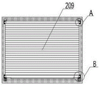
FIG. 3 is a front view of the folding patch of the present invention;
FIG. 4 is an enlarged view of A of FIG. 3 in accordance with the present invention;
fig. 5 is an enlarged view of B of fig. 3 according to the present invention.
In the figure: 1 temperature controller body, 2 using device, 201 mounting box, 202 first magnet strip, 203 metal frame transparent cover, 204 rotating shaft, 205 portable block, 206 first connecting rod, 207 sliding block, 208 spring, 209 folding blocking cloth, 210 second connecting rod, 211 first magnet and 212 second magnet.
Detailed Description
The technical solutions in the embodiments of the present invention will be clearly and completely described below with reference to the drawings in the embodiments of the present invention, and it is obvious that the described embodiments are only a part of the embodiments of the present invention, and not all of the embodiments. All other embodiments, which can be derived by a person skilled in the art from the embodiments given herein without making any creative effort, shall fall within the protection scope of the present invention.
Examples of which are illustrated in the accompanying drawings, wherein like reference numerals refer to the same or similar elements or elements having the same or similar function throughout. The embodiments described below with reference to the drawings are illustrative and intended to be illustrative of the utility model and are not to be construed as limiting the utility model.
In the description of the present invention, it is to be understood that the terms "central," "longitudinal," "lateral," "length," "width," "thickness," "upper," "lower," "front," "rear," "left," "right," "vertical," "horizontal," "top," "bottom," "inner," "outer," "clockwise," "counterclockwise," "axial," "radial," "circumferential," and the like are used in the orientations and positional relationships indicated in the drawings for convenience in describing the utility model and to simplify the description, and are not intended to indicate or imply that the referenced devices or elements must have a particular orientation, be constructed and operated in a particular orientation, and are therefore not to be considered limiting of the utility model.
In the present invention, unless otherwise expressly stated or limited, the terms "mounted," "connected," "secured," and the like are to be construed broadly and can, for example, be fixedly connected, detachably connected, or integrally formed; can be mechanically or electrically connected; either directly or indirectly through intervening media, either internally or in any other relationship. The specific meanings of the above terms in the present invention can be understood by those skilled in the art according to specific situations.
As shown in fig. 1 to 5, the present invention provides a technical solution: a temperature controller with a protection function comprises a temperature controller body 1 and a using device 2, wherein the using device 2 comprises a mounting box 201, a first magnet strip 202, a metal frame transparent cover 203, a rotating shaft 204, a portable block 205, a first connecting rod 206, a sliding block 207, a spring 208, a folding type blocking cloth 209, a second connecting rod 210, a first iron-absorbing stone 211 and a second iron-absorbing stone 212, the temperature controller body 1 is arranged in the mounting box 201, one side of the inner wall of the mounting box 201 is arranged with the first magnet strip 202, the metal frame transparent cover 203 is rotatably connected with one side of the inner wall of the mounting box 201 through the rotating shaft 204, the front of the metal frame transparent cover 203 is fixedly connected with the portable block 205, one side of the back of the metal frame transparent cover 203 is attracted with the first magnet strip 202, the mounting box 201 is provided with a sliding groove, the mounting box 201, the first magnet strip 202, the metal frame transparent cover 203, the rotating shaft 204 and the portable block 205 are arranged, the user can turn over the metal frame transparent cover 203 by turning over the metal frame transparent cover 203, because the first magnet strip 202 and the metal frame transparent cover 203 can be attracted, thereby playing a role of protection, wherein the metal frame transparent cover 203 is convenient to turn over by using the handle block 205, thereby achieving an effect of convenient use, one end of the first connecting rod 206 is fixedly connected with the front surface of the sliding block 207, the outer wall of the sliding block 207 is slidably connected with the inner wall of the sliding groove, one end of the spring 208 is fixedly connected with one side of the sliding groove, the other end of the spring 208 is fixedly connected with one side of the sliding block 207, one side of the folding blocking cloth 209 is fixedly connected with one side of the first connecting rod 206, the other side of the folding blocking cloth 209 is fixedly connected with one side of the second connecting rod 210, one end of the second connecting rod 210 is fixedly connected with the front surface of the first magnet 211, the outer wall of the first magnet 211 is slidably connected with the inner wall of the sliding groove, the first magnet 211 is attracted with the second magnet 212, the second magnet 212 is fixedly arranged on the other side of the inner wall of the sliding groove, and by arranging the first connecting rod 206, the sliding block 207, the spring 208, the folding-type blocking cloth 209, the second connecting rod 210, the first magnet 211 and the second magnet 212, and by pulling the second connecting rod 210, because the folding-type blocking cloth 209 has a certain folding effect, when the second connecting rod 210 is completely pulled, the first magnet 211 and the second magnet 212 are attracted until the first magnet 211 and the second magnet 212 are attracted, so that protection is performed, wherein by using the spring 208, the spring 208 has certain elasticity, when the first magnet 211 and the second magnet 212 are separated from the attraction state, the spring 208 rebounds, the folding-type blocking cloth 209 can be conveniently and rapidly folded, and the effect of convenience is achieved.
When using, the user is through upset metal frame translucent cover 203, because first magnet strip 202 and metal frame translucent cover 203 can the actuation, thereby played the effect of protection, wherein through using portable piece 205, be convenient for overturn metal frame translucent cover 203, through pulling second connecting rod 210, because foldable fender cloth 209 has certain folding effect, when pulling second connecting rod 210 completely, until first magnet 211 and the actuation of second magnet 212, thereby protect, wherein, through using spring 208, spring 208 has certain elasticity, when making first magnet 211 and second magnet 212 break away from the actuation state, spring 208 kick-backs, be convenient for can pack up foldable fender cloth 209 fast.
In summary, by arranging the mounting box 201, the first magnet strip 202, the metal frame transparent cover 203, the rotating shaft 204 and the portable block 205, the user can rotate the metal frame transparent cover 203 by turning over the metal frame transparent cover 203, and the first magnet strip 202 and the metal frame transparent cover 203 can be attracted to protect the user, so that the metal frame transparent cover 203 can be conveniently turned over by using the portable block 205, and the effect of convenient use is achieved.
Through setting up first connecting rod 206, slider 207, spring 208, foldable fender cloth 209, second connecting rod 210, first magnet 211 and second magnet 212, through pulling second connecting rod 210, because foldable fender cloth 209 has certain folding effect, when pulling second connecting rod 210 completely, until first magnet 211 and second magnet 212 actuation, thereby protect, wherein, through using spring 208, spring 208 has certain elasticity, when making first magnet 211 and second magnet 212 break away from the actuation state, spring 208 kick-backs, be convenient for can pack up foldable fender cloth 209 fast, the effect of being convenient for has been reached.
It is noted that, herein, relational terms such as first and second, and the like may be used solely to distinguish one entity or action from another entity or action without necessarily requiring or implying any actual such relationship or order between such entities or actions. Also, the terms "comprises," "comprising," or any other variation thereof, are intended to cover a non-exclusive inclusion, such that a process, method, article, or apparatus that comprises a list of elements does not include only those elements but may include other elements not expressly listed or inherent to such process, method, article, or apparatus.
Finally, it should be noted that: although the present invention has been described in detail with reference to the foregoing embodiments, it will be apparent to those skilled in the art that changes may be made in the embodiments and/or equivalents thereof without departing from the spirit and scope of the utility model. Any modification, equivalent replacement, or improvement made within the spirit and principle of the present invention should be included in the protection scope of the present invention.
Claims (7)
1. The utility model provides a temperature controller that possesses safeguard function, includes temperature controller body (1) and operative installations (2), its characterized in that: the using device (2) comprises a mounting box (201), a first magnet strip (202), a metal frame transparent cover (203), a rotating shaft (204), a portable block (205), a first connecting rod (206), a sliding block (207), a spring (208), a foldable blocking cloth (209), a second connecting rod (210), a first magnet (211) and a second magnet (212), the temperature controller body (1) is arranged in the mounting box (201), one side of the inner wall of the mounting box (201) is arranged with the first magnet strip (202), the metal frame transparent cover (203) is rotatably connected with one side of the inner wall of the mounting box (201) through the rotating shaft (204), and a sliding groove is formed in the mounting box (201).
2. The thermostat with protection function of claim 1, characterized in that: the front surface of the metal frame transparent cover (203) is fixedly connected with the portable block (205).
3. The thermostat with protection function of claim 1, characterized in that: one side of the back surface of the metal frame transparent cover (203) is attracted with the first magnet strip (202).
4. The thermostat with protection function of claim 1, characterized in that: one end of the first connecting rod (206) is fixedly connected with the front surface of the sliding block (207), and the outer wall of the sliding block (207) is connected with the inner wall of the sliding groove in a sliding mode.
5. The thermostat with protection function of claim 1, characterized in that: one end of the spring (208) is fixedly connected with one side of the inner wall of the sliding groove, and the other end of the spring (208) is fixedly connected with one side of the sliding block (207).
6. The thermostat with protection function of claim 1, characterized in that: one side of the folding type blocking cloth (209) is fixedly connected with one side of the first connecting rod (206), the other side of the folding type blocking cloth (209) is fixedly connected with one side of the second connecting rod (210), and one end of the second connecting rod (210) is fixedly connected with the front face of the first iron-absorbing stone (211).
7. The thermostat with protection function of claim 1, characterized in that: the outer wall of the first magnet (211) is connected with the inner wall of the sliding groove in a sliding mode, the first magnet (211) is attracted with the second magnet (212), and the second magnet (212) is fixedly installed on the other side of the inner wall of the sliding groove.
Priority Applications (1)
| Application Number | Priority Date | Filing Date | Title |
|---|---|---|---|
| CN202122743235.8U CN216526907U (en) | 2021-11-10 | 2021-11-10 | Temperature controller with protection function |
Applications Claiming Priority (1)
| Application Number | Priority Date | Filing Date | Title |
|---|---|---|---|
| CN202122743235.8U CN216526907U (en) | 2021-11-10 | 2021-11-10 | Temperature controller with protection function |
Publications (1)
| Publication Number | Publication Date |
|---|---|
| CN216526907U true CN216526907U (en) | 2022-05-13 |
Family
ID=81529405
Family Applications (1)
| Application Number | Title | Priority Date | Filing Date |
|---|---|---|---|
| CN202122743235.8U Active CN216526907U (en) | 2021-11-10 | 2021-11-10 | Temperature controller with protection function |
Country Status (1)
| Country | Link |
|---|---|
| CN (1) | CN216526907U (en) |
-
2021
- 2021-11-10 CN CN202122743235.8U patent/CN216526907U/en active Active
Similar Documents
| Publication | Publication Date | Title |
|---|---|---|
| CN204298638U (en) | Roller washing machine protecgulum door and roller washing machine | |
| CN208079581U (en) | A kind of display control panel | |
| CN216526907U (en) | Temperature controller with protection function | |
| CN206370377U (en) | One kind three keeps off formula switch and its control circuit | |
| CN202269914U (en) | Power-off protector for toaster | |
| CN216120072U (en) | Manual reset temperature controller | |
| CN108580364A (en) | A kind of cleaning plant of residential central air conditioning air louver | |
| CN210179830U (en) | Vertical heat recovery fresh air fan | |
| CN207362521U (en) | Washing machine | |
| WO2018176379A1 (en) | Guardrail for smart bed | |
| CN206741687U (en) | A kind of remote control | |
| CN208541096U (en) | A kind of electric curtain controller | |
| CN220043924U (en) | Hidden intelligent home controller | |
| CN213847205U (en) | Household appliance control device | |
| CN218645746U (en) | Wind-guiding door support and air conditioner | |
| CN215377322U (en) | High-sensitivity temperature controller | |
| CN211184482U (en) | Intelligent fan controller based on bluetooth | |
| CN214228651U (en) | Display device of automatic control cabinet of electric appliance | |
| CN216404824U (en) | Support drum type washing machine master control display screen of TFT demonstration | |
| CN216527117U (en) | A glass apron for intelligent house | |
| CN210720993U (en) | VR projector device | |
| CN211024264U (en) | Intelligent microwave kitchen ware disinfection cabinet | |
| CN211645740U (en) | Multifunctional vertical mirror ironing machine | |
| CN207338749U (en) | A kind of rapid installation switch jack assemblies | |
| CN214228623U (en) | Portable temperature control device |
Legal Events
| Date | Code | Title | Description |
|---|---|---|---|
| GR01 | Patent grant | ||
| GR01 | Patent grant | ||
| TR01 | Transfer of patent right | ||
| TR01 | Transfer of patent right |
Effective date of registration: 20220525 Address after: 154600 50m across from the meteorological observatory, Taobei street, Taoshan District, Qitaihe City, Heilongjiang Province Patentee after: Qitaihe Gaokuiqiang Sports Equipment Co.,Ltd. Address before: 230071 room 1829, 18 / F, building D, Zhidi square office building, about 60 meters southeast of the intersection of Huaining road and Longtu Road, Shushan District, Hefei City, Anhui Province Patentee before: Wang Chuanyan |