CN216472067U - A robot for cargo handling - Google Patents
A robot for cargo handling Download PDFInfo
- Publication number
- CN216472067U CN216472067U CN202220021546.5U CN202220021546U CN216472067U CN 216472067 U CN216472067 U CN 216472067U CN 202220021546 U CN202220021546 U CN 202220021546U CN 216472067 U CN216472067 U CN 216472067U
- Authority
- CN
- China
- Prior art keywords
- robot
- handling
- unit
- goods
- lifting screw
- Prior art date
- Legal status (The legal status is an assumption and is not a legal conclusion. Google has not performed a legal analysis and makes no representation as to the accuracy of the status listed.)
- Expired - Fee Related
Links
- 230000005540 biological transmission Effects 0.000 claims description 26
- 230000003014 reinforcing effect Effects 0.000 claims description 10
- 238000003860 storage Methods 0.000 claims description 3
- 238000004519 manufacturing process Methods 0.000 abstract description 4
- 238000000034 method Methods 0.000 description 5
- 230000009286 beneficial effect Effects 0.000 description 2
- 238000010586 diagram Methods 0.000 description 2
- 230000004075 alteration Effects 0.000 description 1
- 238000009826 distribution Methods 0.000 description 1
- 238000012986 modification Methods 0.000 description 1
- 230000004048 modification Effects 0.000 description 1
- 238000012856 packing Methods 0.000 description 1
- 238000006467 substitution reaction Methods 0.000 description 1
Images


Landscapes
- Handcart (AREA)
Abstract
The utility model discloses a robot for cargo handling belongs to cargo handling production field. The utility model discloses a robot for cargo handling, include the mobile unit and install the unit of placing in the mobile unit upper end, the mobile unit includes the backup pad and installs the support frame in the backup pad upper end, the inboard of support frame is provided with lifting screw, place the unit and include the bearing board and install the connecting piece in bearing board one side, connecting piece and lifting screw threaded connection, the both sides of connecting piece are provided with the locating part, when using transfer robot, accessible lifting screw drives the connecting piece and removes, and then drive the bearing board and descend, make it descend behind the lower extreme of goods, move the goods to the bearing board upper end, later promote the mobile unit and make the goods remove, after moving the assigned position, accessible lifting screw drives the bearing board and removes suitable height and lift the goods off, high durability and convenient use, and simple operation.
Description
Technical Field
The utility model belongs to cargo handling production field, more specifically the utility model relates to a robot for cargo handling.
Background
The cargo handling refers to a general term for carrying out short-distance moving operation on the cargo in the transportation and production process. Transporting important components of the production process. The main contents comprise: cargo stacking, cargo entering and exiting and cargo classification are mainly performed in cargo distribution places, such as a freight station, a port, a wharf, an airport, a logistics center and the like. According to the packing form, shape and style of goods, the method is generally divided into the following steps: single cargo handling, unit cargo handling, bulk handling.
When carrying the goods, often use the fork truck that can remove to carry out the goods, but fork truck is bulky, and it is comparatively inconvenient to remove, and higher place is placed to ordinary shallow inconvenient with the goods, and the manual work is comparatively hard when going on going up unloading, uses comparatively inconveniently.
SUMMERY OF THE UTILITY MODEL
The utility model aims to overcome among the prior art that ordinary shallow is inconvenient places the higher place with the goods, provides a robot for cargo handling to it is not enough more than solving, facilitate the use.
In order to achieve the above purpose, the utility model provides a technical scheme does:
the utility model discloses a robot for cargo handling, including mobile unit and the unit of placing installed in the mobile unit upper end, the mobile unit includes the backup pad and installs the support frame in the backup pad upper end, and the inboard of support frame is provided with the lifting screw, and the lifting screw is connected with the unit of placing;
the placing unit comprises a bearing plate and a connecting piece arranged on one side of the bearing plate, the connecting piece is in threaded connection with the lifting screw, and limiting pieces are arranged on two sides of the connecting piece.
Preferably, one side of the supporting plate is provided with a fixedly mounted reinforcing rod, the lower ends of the supporting plate and the reinforcing rod are provided with universal wheels, and the other side of the supporting plate is provided with an auxiliary pushing handle.
Preferably, the side of the support frame is provided with a limiting sliding groove, and the limiting part is movably arranged inside the limiting sliding groove.
Preferably, the two sides of the limiting part are provided with movable openings, and the rotating wheels are arranged inside the movable openings.
Preferably, a feeding inclined plate is arranged on the side surface of the bearing plate, and a transmission unit is arranged at the upper end of the bearing plate.
Preferably, the lower extreme of bearing board is provided with accomodates the groove, accomodates groove and reinforcing bar size phase-match.
Preferably, the transmission unit comprises a movable roller and a transmission head arranged at one end of the movable roller, the movable rollers at the upper end of the bearing plate are connected in pairs through connecting rods, the adjacent transmission heads are connected in pairs through transmission belts, the transmission head at one end is connected with the driving head, and the driving head is connected with the output end of the driving device.
Preferably, the middle part of the connecting rod is provided with a limiting ring, the upper end of the limiting ring is provided with a movable ball, and the limiting ring is movably arranged in the bearing plate.
Adopt the technical scheme provided by the utility model, compare with prior art, have following beneficial effect:
compared with the prior art, the beneficial effects of the utility model are as follows:
(1) the utility model discloses a robot for cargo handling, when using transfer robot, can start driving motor and drive the connecting piece through the lifting screw and remove, and then drive the bearing board and descend, make it descend to the lower extreme of goods after, push away the removal unit through the assistance and remove, and then make the support frame move to one side of goods, and then move the goods to the bearing board upper end, later promote the removal unit and make the goods move, after moving to the assigned position, can drive the bearing board to move to suitable height through the lifting screw and lift the goods off, high durability and convenient use, easy operation;
(2) the utility model discloses a robot for cargo handling, when goods material loading or unloading, can start driving motor and drive the driving head and rotate, and then drive the transmission head and rotate, adjacent transmission head carries out mutual transmission through driving belt, and then drives the movable roller bearing of one side and rotate, and the supplementary goods of convenience when unloading in the goods removes, makes things convenient for the transport of goods, uses manpower sparingly.
Drawings
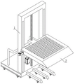
Fig. 1 is a schematic view of the overall structure of the present invention;
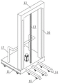
fig. 2 is a schematic structural diagram of a mobile unit according to the present invention;
FIG. 3 is a schematic structural view of the placing unit of the present invention;
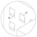
fig. 4 is an enlarged schematic structural view of a portion a in fig. 3 according to the present invention;
FIG. 5 is a schematic view of the structure of the storage groove of the present invention;
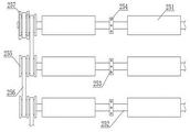
fig. 6 is a schematic structural diagram of the transmission unit of the present invention.
In the figure: 1. a mobile unit; 11. a support plate; 12. a support frame; 13. a lifting screw; 14. a reinforcing rod; 15. a universal wheel; 16. a limiting chute; 17. auxiliary push handles; 2. a placing unit; 21. a support plate; 22. a connecting member; 23. a limiting member; 24. a feeding inclined plate; 25. a transmission unit; 251. a movable roller; 252. a connecting rod; 253. a limiting ring; 254. a movable ball; 255. a drive head; 256. a drive belt; 257. a drive head; 26. a movable opening; 27. a rotating wheel; 28. a receiving groove.
Detailed Description
The technical solutions in the embodiments of the present invention will be described clearly and completely with reference to the accompanying drawings in the embodiments of the present invention, and it is obvious that the described embodiments are only some embodiments of the present invention, not all embodiments. Based on the embodiments in the present invention, all other embodiments obtained by a person skilled in the art without creative work belong to the protection scope of the present invention.
For a further understanding of the present invention, reference is made to the following detailed description taken in conjunction with the accompanying drawings.
With reference to fig. 1, the utility model discloses a robot for goods handling, including mobile unit 1 and the unit 2 of placing of installing in mobile unit 1 upper end.
The invention will be further described with reference to the following examples
Example 1
Referring to fig. 1-4, the moving unit 1 includes a supporting plate 11 and a supporting frame 12 installed at the upper end of the supporting plate 11, a limiting sliding groove 16 is disposed on the side surface of the supporting frame 12, a lifting screw 13 is disposed on the inner side of the supporting frame 12, the lifting screw 13 is connected with the placing unit 2, and an auxiliary pushing handle 17 is disposed on the other side of the supporting plate 11.
The placing unit 2 comprises a bearing plate 21 and a connecting piece 22 installed on one side of the bearing plate 21, the connecting piece 22 is in threaded connection with the lifting screw 13, limiting pieces 23 are arranged on two sides of the connecting piece 22, the limiting pieces 23 are movably installed inside the limiting sliding grooves 16, moving openings 26 are formed in two sides of each limiting piece 23, and rotating wheels 27 are arranged inside the moving openings 26.
When using transfer robot, can start driving motor and drive connecting piece 22 through lifting screw 13 and remove, and then drive bearing board 21 and descend, make it descend to the lower extreme of goods after, push away 17 through the assistance and promote mobile unit 1 and remove, and then make support frame 12 remove the one side of goods, and then remove the goods to bearing board 21 upper end, later promote mobile unit 1 and make the goods remove, after removing the assigned position, accessible lifting screw 13 drives bearing board 21 and removes suitable height and lift the goods off, high durability and convenient use, and the operation is simple.
Example 2
Referring to fig. 2 and 5, a reinforcing rod 14 is fixedly installed at one side of the supporting plate 11, and universal wheels 15 are installed at the lower ends of the supporting plate 11 and the reinforcing rod 14.
The lower end of the bearing plate 21 is provided with a receiving groove 28, and the receiving groove 28 is matched with the reinforcing rod 14 in size.
Set up the stiffening rod 14 in the side of backup pad 11, can increase the support area of backup pad 11 when the goods is placed to the bearing board 21 upper end, make to support more firm, and the groove 28 of accomodating that sets up can accomodate stiffening rod 14 when bearing board 21 descends, prevents that bearing board 21 is great with the ground difference when descending, inconvenient unloading.
Example 3
Referring to fig. 6, a loading inclined plate 24 is disposed on a side surface of the support plate 21, and a transmission unit 25 is disposed at an upper end of the support plate 21.
The transmission unit 25 comprises a movable roller 251 and a transmission head 255 arranged at one end of the movable roller 251, the movable rollers 251 at the upper end of the bearing plate 21 are connected in pairs through connecting rods 252, adjacent transmission heads 255 are connected in pairs through transmission belts 256, the transmission head 255 at one end is connected with a driving head 257, and the driving head 257 is connected with the output end of the driving device.
The middle part of the connecting rod 252 is provided with a limiting ring 253, the upper end of the limiting ring 253 is provided with a movable ball 254, and the limiting ring 253 is movably arranged in the bearing plate 21.
When goods material loading or unloading, can start driving motor and drive the driving head 257 and rotate, and then drive the transmission head 255 and rotate, adjacent transmission head 255 carries out mutual transmission through drive belt 256, and then drives the movable roller bearing 251 of one side and rotate, and supplementary goods move when the goods goes up unloading conveniently, makes things convenient for the transport of goods, uses manpower sparingly.
In summary, the following steps: when the transfer robot is used, the driving motor can be started to drive the connecting piece 22 to move through the lifting screw 13, so as to drive the supporting plate 21 to descend, so that the supporting plate is descended to the lower end of a cargo, the moving unit 1 is pushed to move through the auxiliary push handle 17, so that the supporting frame 12 is moved to one side of the cargo, so as to move the cargo to the upper end of the supporting plate 21, then the moving unit 1 is pushed to move the cargo, after the cargo is moved to a specified position, the supporting plate 21 is driven to move to a proper height through the lifting screw 13, when the cargo is loaded or unloaded, the driving motor can be started to drive the driving head 257 to rotate, so as to drive the driving heads 255 to rotate, the adjacent driving heads 255 are mutually driven through the driving belt 256, so as to drive the movable roller 251 on one side to rotate, so as to facilitate the auxiliary cargo moving when the cargo is loaded or unloaded, the carrying of goods is convenient, and the manpower is saved.
It is noted that, herein, relational terms such as first and second, and the like may be used solely to distinguish one entity or action from another entity or action without necessarily requiring or implying any actual such relationship or order between such entities or actions. Also, the terms "comprises," "comprising," or any other variation thereof, are intended to cover a non-exclusive inclusion, such that a process, method, article, or apparatus that comprises a list of elements does not include only those elements but may include other elements not expressly listed or inherent to such process, method, article, or apparatus.
Although embodiments of the present invention have been shown and described, it will be appreciated by those skilled in the art that changes, modifications, substitutions and alterations can be made in these embodiments without departing from the principles and spirit of the invention, the scope of which is defined in the appended claims and their equivalents.
Claims (8)
1. A robot for cargo handling, comprising a mobile unit (1) and a placement unit (2) mounted at the upper end of the mobile unit (1), characterized in that: the moving unit (1) comprises a supporting plate (11) and a supporting frame (12) arranged at the upper end of the supporting plate (11), a lifting screw (13) is arranged on the inner side of the supporting frame (12), and the lifting screw (13) is connected with the placing unit (2);
the placing unit (2) comprises a bearing plate (21) and a connecting piece (22) arranged on one side of the bearing plate (21), the connecting piece (22) is in threaded connection with the lifting screw (13), and limiting pieces (23) are arranged on two sides of the connecting piece (22).
2. A robot for handling of goods according to claim 1, characterized in that: one side of the supporting plate (11) is provided with a fixedly installed reinforcing rod (14), the lower ends of the supporting plate (11) and the reinforcing rod (14) are provided with universal wheels (15), and the other side of the supporting plate (11) is provided with an auxiliary pushing handle (17).
3. A robot for handling of goods according to claim 2, characterized in that: the side of the support frame (12) is provided with a limiting sliding groove (16), and the limiting part (23) is movably arranged in the limiting sliding groove (16).
4. A robot for handling of goods according to claim 3, characterized in that: the two sides of the limiting part (23) are provided with movable openings (26), and rotating wheels (27) are arranged inside the movable openings (26).
5. A robot for handling of goods according to claim 4, characterized in that: a feeding inclined plate (24) is arranged on the side surface of the bearing plate (21), and a transmission unit (25) is arranged at the upper end of the bearing plate (21).
6. A robot for handling of goods according to claim 5, characterized in that: the lower end of the bearing plate (21) is provided with a storage groove (28), and the storage groove (28) is matched with the reinforcing rod (14) in size.
7. A robot for handling of goods according to claim 6, characterized in that: the transmission unit (25) comprises movable rollers (251) and transmission heads (255) arranged at one ends of the movable rollers (251), the movable rollers (251) at the upper ends of the bearing plates (21) are connected in pairs through connecting rods (252), the adjacent transmission heads (255) are connected in pairs through transmission belts (256), the transmission head (255) at one end is connected with a driving head (257), and the driving head (257) is connected with the output end of the driving device.
8. A robot for handling of goods according to claim 7, characterized in that: the middle part of the connecting rod (252) is provided with a limiting ring (253), the upper end of the limiting ring (253) is provided with a movable ball (254), and the limiting ring (253) is movably arranged in the bearing plate (21).
Priority Applications (1)
| Application Number | Priority Date | Filing Date | Title |
|---|---|---|---|
| CN202220021546.5U CN216472067U (en) | 2022-01-06 | 2022-01-06 | A robot for cargo handling |
Applications Claiming Priority (1)
| Application Number | Priority Date | Filing Date | Title |
|---|---|---|---|
| CN202220021546.5U CN216472067U (en) | 2022-01-06 | 2022-01-06 | A robot for cargo handling |
Publications (1)
| Publication Number | Publication Date |
|---|---|
| CN216472067U true CN216472067U (en) | 2022-05-10 |
Family
ID=81434678
Family Applications (1)
| Application Number | Title | Priority Date | Filing Date |
|---|---|---|---|
| CN202220021546.5U Expired - Fee Related CN216472067U (en) | 2022-01-06 | 2022-01-06 | A robot for cargo handling |
Country Status (1)
| Country | Link |
|---|---|
| CN (1) | CN216472067U (en) |
-
2022
- 2022-01-06 CN CN202220021546.5U patent/CN216472067U/en not_active Expired - Fee Related
Similar Documents
| Publication | Publication Date | Title |
|---|---|---|
| CN212891450U (en) | Battery package transfer device | |
| CN114590566A (en) | Continuous cargo pushing device and pushing method | |
| CN216472067U (en) | A robot for cargo handling | |
| CN210084864U (en) | Make things convenient for manual heap of high car of widened type of shovel goods | |
| CN218579098U (en) | Pallet cargo separation device for logistics transportation | |
| CN216660860U (en) | Former piece rack of glass with screens is adjusted | |
| CN207565646U (en) | A kind of cart convenient for handling goods | |
| CN213976190U (en) | Large-scale parcel auxiliary device that unloads that commodity circulation was used | |
| CN114633981A (en) | A convenient type handling device for logistics storage | |
| CN213413895U (en) | Novel container stacking system carrying cart | |
| CN213568331U (en) | Advanced manufactured product conveying device | |
| CN212531389U (en) | Stacking device and container loading system | |
| CN111153226A (en) | Automatic loading equipment for container | |
| CN217808613U (en) | Pure electric forklift with anti-toppling function | |
| CN217100102U (en) | Transfer device is used in processing of auto mold accessory | |
| CN218908614U (en) | Agricultural product storage transfer device | |
| CN211643905U (en) | Automatic loading equipment for container | |
| CN113665919B (en) | Packing production line for processing straight bar steel bars | |
| CN214494643U (en) | Labor-saving unloading truck | |
| CN213262486U (en) | Commodity circulation conveyer for supply chain | |
| CN218661949U (en) | Cargo transfer trolley | |
| CN217969571U (en) | Logistics freight transport cart convenient to lift | |
| CN211847027U (en) | Rotatable goods transport vehicle based on magnetic navigation | |
| CN213010088U (en) | Small truck unloading device for intelligent storage | |
| CN217024035U (en) | Lifting type logistics transportation equipment capable of automatically loading and unloading articles |
Legal Events
| Date | Code | Title | Description |
|---|---|---|---|
| GR01 | Patent grant | ||
| GR01 | Patent grant | ||
| CF01 | Termination of patent right due to non-payment of annual fee | ||
| CF01 | Termination of patent right due to non-payment of annual fee |
Granted publication date: 20220510 |