CN216455686U - Emergency department uses ambulance cot - Google Patents
Emergency department uses ambulance cot Download PDFInfo
- Publication number
- CN216455686U CN216455686U CN202220005937.8U CN202220005937U CN216455686U CN 216455686 U CN216455686 U CN 216455686U CN 202220005937 U CN202220005937 U CN 202220005937U CN 216455686 U CN216455686 U CN 216455686U
- Authority
- CN
- China
- Prior art keywords
- connecting rod
- fixedly connected
- stretcher
- emergency department
- ambulance cot
- Prior art date
- Legal status (The legal status is an assumption and is not a legal conclusion. Google has not performed a legal analysis and makes no representation as to the accuracy of the status listed.)
- Expired - Fee Related
Links
- 244000309464 bull Species 0.000 claims 3
- 238000010586 diagram Methods 0.000 description 4
- 208000027418 Wounds and injury Diseases 0.000 description 2
- 230000008602 contraction Effects 0.000 description 2
- 230000006378 damage Effects 0.000 description 2
- 208000014674 injury Diseases 0.000 description 2
- 238000000034 method Methods 0.000 description 2
- 230000004048 modification Effects 0.000 description 2
- 238000012986 modification Methods 0.000 description 2
- 230000004888 barrier function Effects 0.000 description 1
- 230000009286 beneficial effect Effects 0.000 description 1
- 230000008859 change Effects 0.000 description 1
- 230000007812 deficiency Effects 0.000 description 1
- 210000005069 ears Anatomy 0.000 description 1
- 230000006872 improvement Effects 0.000 description 1
- 230000007246 mechanism Effects 0.000 description 1
- 230000008569 process Effects 0.000 description 1
- 239000002699 waste material Substances 0.000 description 1
Images


Landscapes
- Invalid Beds And Related Equipment (AREA)
Abstract
Description
技术领域technical field
本实用新型属于医疗器械技术领域,特别涉及一种急诊科用救护床。The utility model belongs to the technical field of medical devices, in particular to an ambulance bed for emergency departments.
背景技术Background technique
救护床作为现在医疗救援的主要救援工具,在医疗中起着重要的作用,现有的救护床由床架和行走机构组成,在对病人进行急诊转移时,在坑洼路面、狭窄路面或斜坡路面时,不易行走,往往需要采用担架把病人抬到救护床侧边,然后转移到救护床上,而急诊病人一般情况比较紧急,在来回转移过程中容易加重病情,对病人产生危险性。因此出诊时经常需要携带救护床以及担架;携带时极为不便。且在推动救护床的路程上如果遇到无法向前推动的状况,再折回拿担架极为浪费时间。且在不使用救护床时,由于救护床体积较大,极为占用空间,存放不变。As the main rescue tool for medical rescue now, the ambulance bed plays an important role in medical treatment. The existing ambulance bed is composed of a bed frame and a walking mechanism. When emergency transfer of patients, it can be used on potholes, narrow roads or slopes. On the road, it is not easy to walk, and it is often necessary to use a stretcher to lift the patient to the side of the ambulance bed, and then transfer it to the ambulance bed. However, emergency patients are generally more urgent, and it is easy to aggravate the condition during the back and forth transfer process, which is dangerous to the patient. Therefore, it is often necessary to carry an ambulance bed and a stretcher when visiting a doctor; it is extremely inconvenient to carry. In addition, if the ambulance cot cannot be pushed forward, it is a waste of time to go back and take the stretcher. And when the ambulance bed is not in use, because the ambulance bed is large in size, it takes up a lot of space and cannot be stored.
为解决上述问题,我们提供了一种方便携带、救护床与担架为一体且方便收纳的一种急诊科用救护床。In order to solve the above problems, we provide an ambulance bed for emergency department that is easy to carry, integrates the ambulance bed and the stretcher, and is easy to store.
实用新型内容Utility model content
本实用新型的目的在于克服现有技术中存在的不足而提供一种急诊科用救护床。The purpose of the utility model is to overcome the deficiencies in the prior art and provide an ambulance bed for emergency department.
本实用新型的目的是这样实现的:一种急诊科用救护床,包括有四个升降杆,升降杆下端连接有万向轮,所述每两个升降杆上端固定连接有连接杆一,连接杆一上表面固定设置有两个转杆,转杆上端固定连接有连接杆二,两个连接杆二内侧可拆卸的设置有担架,两个连接杆二之间可相对移动,连接杆二下表面前后端分别固定连接有卡座。The purpose of the utility model is achieved as follows: an ambulance bed for emergency department, including four lifting rods, the lower ends of the lifting rods are connected with universal wheels, and the upper ends of the two lifting rods are fixedly connected with a connecting rod one, which is connected to Two rotating rods are fixedly arranged on the upper surface of the first rod, and the upper end of the rotating rod is fixedly connected with the second connecting rod. The inner side of the two connecting rods is detachably provided with a stretcher. The front and rear ends of the surface are respectively fixedly connected with a card seat.
进一步的,所述担架包括有面板,面板左右两侧固定连接有架杆,每个架杆下端可折叠的设置有两个支撑杆。Further, the stretcher includes a panel, the left and right sides of the panel are fixedly connected with frame rods, and the lower end of each frame rod is foldable and provided with two support rods.
进一步的,所述转杆上可转动的设置有伸展板,相对的两个伸展板之间可转动的设置有连接件,伸展板外端开设有矩形凹槽,矩形凹槽内固定连接有耳板,耳板内与连接件转动连接。Further, a stretch plate is rotatably provided on the rotating rod, a connecting piece is rotatably provided between the two opposite stretch plates, a rectangular groove is opened at the outer end of the stretch plate, and an ear is fixedly connected in the rectangular groove. The inside of the ear plate is rotatably connected with the connecting piece.
进一步的,所述连接杆二前后两端分别可转动的设置有推杆,推杆为L形结构。Further, the front and rear ends of the second connecting rod are respectively rotatably provided with push rods, and the push rods have an L-shaped structure.
进一步的,所述连接杆二中部外侧设置有挡板。Further, a baffle plate is provided on the outer side of the middle part of the second connecting rod.
有益效果:该装置可以实现对患者的转运,同时可以采用两种转运方式,当地面较为平坦时可以采用推动式移动,当不适合推动时可以采用两人抬动担架进行转运;在不使用时可以将其进行收缩,不占用存放空间,使用时简便快捷,适应急诊科室的快速高效的转运病人。Beneficial effects: the device can realize the transfer of patients, and can adopt two transfer modes at the same time, when the ground is relatively flat, the push-type movement can be used, and when it is not suitable for pushing, two people can lift the stretcher for transfer; when not in use It can be shrunk, does not occupy storage space, is convenient and quick to use, and is suitable for fast and efficient patient transfer in emergency departments.
附图说明Description of drawings
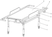
图1为实用新型的结构示意图。Figure 1 is a schematic structural diagram of the utility model.
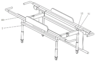
图2为实用新型的担架结构示意图。FIG. 2 is a schematic diagram of the structure of the stretcher of the utility model.
图3为实用新型的收缩时结构示意图。FIG. 3 is a schematic view of the structure of the utility model when it shrinks.
图4为实用新型的担架取出时结构示意图。4 is a schematic structural diagram of the stretcher of the utility model when it is taken out.
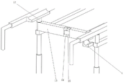
图5为实用新型的局部结构示意图。Figure 5 is a schematic diagram of a partial structure of the utility model.
附图标记说明:Description of reference numbers:
1.万向轮、2.升降杆、3.挡板、4.卡座、5.推杆、6.面板、7.连接杆一、8.支撑杆、9.架杆、10.连接杆二、11.弧形卡槽、12.转杆、13.伸展板、14.耳板、15.连接件。1. Universal wheel, 2. Lifting rod, 3. Baffle plate, 4. Card seat, 5. Push rod, 6. Panel, 7. Connecting
具体实施方式Detailed ways
实施例1Example 1
如图1-5所示,本实用新型的目的是这样实现的:一种急诊科用救护床,包括有四个升降杆2,升降杆2可以调节装置的高度,升降杆2下端连接有万向轮1,万向轮1方便转运;所述每两个升降杆2上端固定连接有连接杆一7,连接杆一7上表面固定设置有两个转杆12,转杆12上端固定连接有连接杆二10,两个连接杆二10内侧可拆卸的设置有担架,两个连接杆二10之间可相对移动,连接杆二10下表面前后端分别固定连接有卡座4,卡座4可以用来卡接担架,不使用时将担架卡在卡座4上,节约存放空间。As shown in Figures 1-5, the purpose of the present utility model is achieved in this way: an ambulance cot for emergency department, including four
担架包括有面板6,面板6左右两侧固定连接有架杆9,每个架杆9下端可折叠的设置有两个支撑杆8,可以实现对担架进行支撑;连接杆二10内测开设有弧形卡槽11,架杆9卡接在弧形卡槽11内,可实现对架杆9的支撑与卡接,同时对两个连接杆二10之间的距离进行固定,避免伸展板13之间转动,导致两个连接杆二10之间距离发生变化。连接杆二10前后两端分别可转动的设置有推杆5,推杆5为L形结构,根据使用者的习惯可以调节推杆5的角度。The stretcher includes a
转杆12上可转动的设置有伸展板13,相对的两个伸展板13之间可转动的设置有连接件15,伸展板13外端开设有矩形凹槽,矩形凹槽内固定连接有耳板14,耳板14内与连接件15转动连接。伸展板13内端后侧为平面,在两个伸展板13完全打开时,两个伸展板13后侧平面之间相互贴合受力,实现对两个伸展板13转动角度的限制,同时能保证两个伸展板13展开角度为90度,使得两个连接杆二10之间展开的距离最大。且该结构可以使得在伸展板13在收缩内,始终保持伸展板13向内转动,收缩后结构更加紧凑,减少占用空间。连接杆二10中部外侧设置有挡板3,挡板3也可以设置为可上下转动的结构,方便对病人抬放,同时对病人起到隔挡的作用。A
本实用新型使用时,可以手持推杆5推动救护床进行移动,推杆5相对连接杆二10可以相对转动,根据个人推动习惯可以调整推杆5的角度。当需要使用担架对患者进行抬动转运时,(例如:因病人体重或者受伤程度搬动病人可能会造成二次伤害,不适合将其直接抬高,可以取出担架,方便将病人移动至担架上。或者因楼梯或者地面不适宜采用推动式担架前行时,可取出担架两人抬动前进。)两人可以手握架杆9将担架从装置内抬出,将病人抬放在担架上,再抬动担架将担架放置在本装置上。当需要将本装置收起时,将担架取出,将架杆9搭在卡座4内,担架此时位于整个装置的侧面;转动推杆5,将推杆5外侧朝下;将左右两侧的连接杆一7进行折叠,此时两对伸展板13转动收缩在连接杆一7与连接杆二10之间,左右两个连接杆一7之间相互贴合,完成对本装置的收缩,可以极大程度的节约存放空间,且在不使用时也更加方便移动,能够通过更窄的门洞或者路面。When the utility model is in use, the ambulance cot can be moved by holding the
在本实用新型的描述中,需要理解的是,术语“中心”、“纵向”、“横向”、“长度”、“宽度”、“厚度”、“上”、“下”、“前”、“后”、“左”、 “右”、“竖直”、“水平”、“顶”、“底”、“内”、“外”、“ 顺时针”、“逆时针”等指示的方位或位置关系为基于附图所示的方位或位置关系,仅是为了便于描述本实用新型和简化描述,而不是指示或暗示所指的设备或元件必须具有特定的方位、以特定的方位构造和操作,因此不能理解为对本实用新型的限制。In the description of the present invention, it should be understood that the terms "center", "longitudinal", "lateral", "length", "width", "thickness", "upper", "lower", "front", "Back", "Left", "Right", "Vertical", "Horizontal", "Top", "Bottom", "Inner", "Outer", "Clockwise", "Counterclockwise" etc. Or the positional relationship is based on the orientation or positional relationship shown in the accompanying drawings, which is only for the convenience of describing the present invention and simplifying the description, rather than indicating or implying that the referred device or element must have a specific orientation, be constructed in a specific orientation and operation, so it cannot be construed as a limitation to the present invention.
以上所述仅为本实用新型的优选实施例而已,并不用以限制本实用新型,对于本领域的技术人员来说,本实用新型可以有各种更改和变化,凡在本实用新型的精神和原则之内,所作的任何修改、等同替换、改进等,均应包含在本实用新型的保护范围之内。The above are only preferred embodiments of the present invention, and are not intended to limit the present invention. For those skilled in the art, the present invention may have various modifications and changes. Within the principle, any modification, equivalent replacement, improvement, etc. made shall be included within the protection scope of the present invention.
Claims (5)
Priority Applications (1)
| Application Number | Priority Date | Filing Date | Title |
|---|---|---|---|
| CN202220005937.8U CN216455686U (en) | 2022-01-05 | 2022-01-05 | Emergency department uses ambulance cot |
Applications Claiming Priority (1)
| Application Number | Priority Date | Filing Date | Title |
|---|---|---|---|
| CN202220005937.8U CN216455686U (en) | 2022-01-05 | 2022-01-05 | Emergency department uses ambulance cot |
Publications (1)
| Publication Number | Publication Date |
|---|---|
| CN216455686U true CN216455686U (en) | 2022-05-10 |
Family
ID=81433580
Family Applications (1)
| Application Number | Title | Priority Date | Filing Date |
|---|---|---|---|
| CN202220005937.8U Expired - Fee Related CN216455686U (en) | 2022-01-05 | 2022-01-05 | Emergency department uses ambulance cot |
Country Status (1)
| Country | Link |
|---|---|
| CN (1) | CN216455686U (en) |
-
2022
- 2022-01-05 CN CN202220005937.8U patent/CN216455686U/en not_active Expired - Fee Related
Similar Documents
| Publication | Publication Date | Title |
|---|---|---|
| CN112043522B (en) | Nursing sickbed capable of reducing secondary injury to patient in moving process | |
| CN209916416U (en) | Movable protective cover | |
| CN212067028U (en) | Ambulance stretcher convenient to fold and store | |
| CN204618609U (en) | A kind of medical stretcher | |
| CN201719454U (en) | Versatile rescue stretcher | |
| CN210932285U (en) | Emergency stretcher | |
| CN216257874U (en) | Multifunctional wheelchair transfer bed | |
| CN209933215U (en) | A patient transfer bed car with a folding guardrail rack | |
| CN214968659U (en) | Be used for old person's osteoporosis to use and help capable ware | |
| CN221654849U (en) | Labor-saving first-aid stretcher | |
| CN2912606Y (en) | Folding crutch | |
| CN115778690B (en) | Portable folding bearing device for rescue | |
| CN213311012U (en) | A medical portable wheelchair | |
| CN221600437U (en) | Stretcher convenient to accomodate | |
| CN221712726U (en) | A foldable and retractable walking frame | |
| CN210728043U (en) | Practical wheelchair capable of being completely unfolded | |
| CN211844590U (en) | Multifunctional baby carriage convenient to fold | |
| CN219835766U (en) | Patient transports support | |
| CN220877084U (en) | Emergency transport vehicle | |
| CN217409167U (en) | Efficient transfer medical bed | |
| CN220938492U (en) | Patient nursing walking aid | |
| CN213641672U (en) | Traditional chinese medical science rehabilitation and health care nursing bed chair | |
| CN221888569U (en) | Multifunctional wheelchair | |
| CN211408318U (en) | Novel accompanying bed | |
| CN219230419U (en) | Rescue stretcher for hospital |
Legal Events
| Date | Code | Title | Description |
|---|---|---|---|
| GR01 | Patent grant | ||
| GR01 | Patent grant | ||
| CF01 | Termination of patent right due to non-payment of annual fee | ||
| CF01 | Termination of patent right due to non-payment of annual fee |
Granted publication date: 20220510 |