CN216450220U - Ladder work safety experience device - Google Patents
Ladder work safety experience device Download PDFInfo
- Publication number
- CN216450220U CN216450220U CN202122226622.4U CN202122226622U CN216450220U CN 216450220 U CN216450220 U CN 216450220U CN 202122226622 U CN202122226622 U CN 202122226622U CN 216450220 U CN216450220 U CN 216450220U
- Authority
- CN
- China
- Prior art keywords
- rod
- vertical
- rods
- vertically connected
- cross
- Prior art date
- Legal status (The legal status is an assumption and is not a legal conclusion. Google has not performed a legal analysis and makes no representation as to the accuracy of the status listed.)
- Active
Links
Images


Landscapes
- Ladders (AREA)
Abstract
本实用新型的梯子作业安全体验装置,底杆水平设置并且相互平行;第一竖杆底端与第一底杆垂直连接,第二竖杆底端与第二底杆垂直连接;第一横杆的一端与第一底杆垂直连接并且另一端与第二底杆垂直连接;第二横杆间隔设置于竖杆顶端之间;第二横杆的一端与第一竖杆垂直连接并且另一端与第二竖杆垂直连接;侧杆包括第一侧杆和第二侧杆并且水平设置;第一侧杆的一端垂直连接于第一底杆外侧部,第二侧杆的一端垂直连接于第二底杆外侧部;底杆与竖杆之间、第一横杆与底杆之间、第二横杆与竖杆之间以及侧杆与底杆之间分别通过三通接头套接连接;三通接头外壁设置锁紧螺孔和锁紧螺钉,锁紧螺钉螺纹连接于锁紧螺孔内;安全绳顶端连接于第二横杆上。
In the ladder operation safety experience device of the utility model, the bottom rods are arranged horizontally and are parallel to each other; the bottom end of the first vertical rod is vertically connected with the first bottom rod, and the bottom end of the second vertical rod is vertically connected with the second bottom rod; the first horizontal rod One end is vertically connected with the first bottom rod and the other end is vertically connected with the second bottom rod; the second horizontal rod is arranged between the top ends of the vertical rods; one end of the second horizontal rod is vertically connected with the first vertical rod The second vertical rod is vertically connected; the side rod includes a first side rod and a second side rod and is arranged horizontally; one end of the first side rod is vertically connected to the outer part of the first bottom rod, and one end of the second side rod is vertically connected to the second side rod The outer part of the bottom rod; the bottom rod and the vertical rod, between the first horizontal rod and the bottom rod, between the second horizontal rod and the vertical rod, and between the side rod and the bottom rod are respectively sleeved and connected by three-way joints; three A locking screw hole and a locking screw are arranged on the outer wall of the through joint, and the locking screw is threadedly connected in the locking screw hole; the top end of the safety rope is connected to the second cross bar.
Description
技术领域technical field
本实用新型涉及一种梯子作业安全体验装置。The utility model relates to a safety experience device for ladder operation.
背景技术Background technique
在梯子上作业时,若操作不当会发生脚底打滑或者梯子打滑的情况,进而导致作业人员从梯子上滑落或坠落的事故,为了提高作业人员的安全意识,需要亲身演示或者体验登梯作业打滑的情况。梯子作业安全体验装置,就是用于演示和体验登梯作业打滑事故的装置,由于该装置设有安全防护措施,所以在体验过程中即使发生打滑事故,也不会导致人员受伤,较为安全。When working on the ladder, if the operation is improper, the sole of the foot or the ladder will slip, which will cause the operator to slip or fall from the ladder. Happening. The ladder operation safety experience device is a device used to demonstrate and experience the slipping accident of boarding operation. Since the device is equipped with safety protection measures, even if a slipping accident occurs during the experience process, it will not cause personnel injury, which is relatively safe.
然而,传统的梯子作业安全体验装置,结构固定而笨重,不易拆装和移动,在施工现场使用不方便。However, the traditional ladder operation safety experience device has a fixed and heavy structure, is not easy to disassemble and move, and is inconvenient to use on the construction site.
实用新型内容Utility model content
本实用新型要解决的技术问题是提供一种更容易拆装移动和更适应施工现场环境的梯子作业安全体验装置。The technical problem to be solved by the utility model is to provide a ladder operation safety experience device which is easier to disassemble, move and adapt to the construction site environment.
为了解决上述技术问题,本实用新型的梯子作业安全体验装置,包括底杆、竖杆、横杆、侧杆、三通接头和安全绳;所述底杆包括第一底杆和第二底杆,所述底杆水平设置并且相互平行;所述竖杆包括第一竖杆和第二竖杆,所述第一竖杆底端与第一底杆垂直连接,所述第二竖杆底端与第二底杆垂直连接;所述横杆包括第一横杆和第二横杆并且相互平行;所述第一横杆相隔设置于所述底杆之间;所述第一横杆的一端与第一底杆垂直连接并且另一端与第二底杆垂直连接;所述第二横杆间隔设置于所述竖杆顶端之间;所述第二横杆的一端与第一竖杆垂直连接并且另一端与第二竖杆垂直连接;所述侧杆包括第一侧杆和第二侧杆并且水平设置;所述第一侧杆的一端垂直连接于所述第一底杆外侧部,所述第二侧杆的一端垂直连接于所述第二底杆外侧部;所述底杆与竖杆之间、所述第一横杆与底杆之间、所述第二横杆与竖杆之间以及所述侧杆与底杆之间分别通过所述三通接头套接连接;所述三通接头外壁设置锁紧螺孔和锁紧螺钉,所述锁紧螺钉螺纹连接于所述锁紧螺孔内;所述安全绳顶端连接于所述第二横杆上。In order to solve the above technical problems, the ladder operation safety experience device of the present invention includes a bottom rod, a vertical rod, a horizontal rod, a side rod, a three-way joint and a safety rope; the bottom rod includes a first bottom rod and a second bottom rod , the bottom rods are arranged horizontally and are parallel to each other; the vertical rods include a first vertical rod and a second vertical rod, the bottom end of the first vertical rod is vertically connected with the first bottom rod, and the bottom end of the second vertical rod It is vertically connected with the second bottom bar; the cross bar includes a first cross bar and a second cross bar and are parallel to each other; the first cross bar is spaced between the bottom bars; one end of the first cross bar It is vertically connected to the first bottom bar and the other end is vertically connected to the second bottom bar; the second horizontal bar is arranged between the top ends of the vertical bars; one end of the second horizontal bar is vertically connected to the first vertical bar And the other end is vertically connected with the second vertical rod; the side rod includes a first side rod and a second side rod and is arranged horizontally; one end of the first side rod is vertically connected to the outer part of the first bottom rod, so One end of the second side rod is vertically connected to the outer side of the second bottom rod; between the bottom rod and the vertical rod, between the first horizontal rod and the bottom rod, and between the second horizontal rod and the vertical rod and between the side rod and the bottom rod are respectively sleeved and connected by the three-way joint; the outer wall of the three-way joint is provided with a locking screw hole and a locking screw, and the locking screw is threadedly connected to the lock The top end of the safety rope is connected to the second cross bar.
所述底杆、竖杆、横杆和侧杆均为方形杆,所述三通接头的接口均为对应的方形口。The bottom rod, the vertical rod, the horizontal rod and the side rod are all square rods, and the interfaces of the three-way joint are all corresponding square ports.
还包括水箱,所述水箱底部两端分别设置有对应所述底杆的卡槽,所述卡槽分别卡接于所述底杆上。It also includes a water tank, and two ends of the bottom of the water tank are respectively provided with clamping grooves corresponding to the bottom rods, and the clamping grooves are respectively clamped on the bottom rods.
所述侧杆和竖杆的位置靠近所述底杆的一端,所述水箱的位置靠近所述底杆的另一端。The position of the side rod and the vertical rod is close to one end of the bottom rod, and the position of the water tank is close to the other end of the bottom rod.
还包括梯子,所述梯子的宽度小于所述底杆之间的间距和小于所述竖杆之间的间距,所述梯子底部倾斜设置于所述底杆之间以及竖杆之间。It also includes a ladder, the width of the ladder is smaller than the spacing between the bottom rods and the spacing between the vertical rods, and the bottom of the ladder is inclined between the bottom rods and between the vertical rods.
采用本实用新型的结构,底杆与竖杆之间、第一横杆与底杆之间、第二横杆与竖杆之间以及侧杆与底杆之间分别通过三通接头套接连接并且通过锁紧螺钉锁定,可以拆分后移动到施工现场进行组装,更容易拆装移动。竖杆和侧杆可以根据需要调整在底杆上的连接位置,使竖杆、侧杆、第二横杆和安全绳更靠近施工位置,进而更适应施工现场环境,而在底杆另一端安装水箱作为配重,在发生坠落事故时可以更平稳地吊住突然下坠的作业人员。水箱灌水后可以作为配重,水箱拆卸放水后还可以作为三通接头和横杆的容纳箱,使用更方便。By adopting the structure of the utility model, the bottom rod and the vertical rod, the first horizontal rod and the bottom rod, the second horizontal rod and the vertical rod, and the side rod and the bottom rod are respectively sleeved and connected by three-way joints And locked by the locking screw, it can be disassembled and moved to the construction site for assembly, which is easier to disassemble and move. The vertical pole and side pole can be adjusted to the connection position on the bottom pole according to the needs, so that the vertical pole, side pole, second cross pole and safety rope are closer to the construction position, which is more suitable for the construction site environment, and is installed on the other end of the bottom pole The water tank acts as a counterweight, which can more smoothly suspend the operator who suddenly falls in the event of a fall accident. After the water tank is filled with water, it can be used as a counterweight. After the water tank is disassembled and released, it can also be used as a holding box for the tee joint and the cross bar, which is more convenient to use.
附图说明Description of drawings
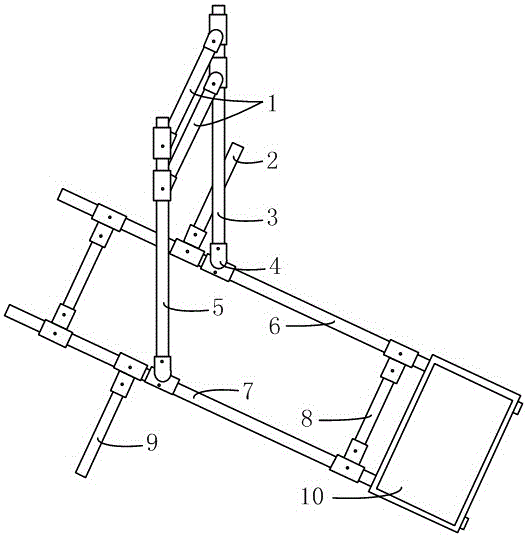
图1为本实用新型的结构示意图。Figure 1 is a schematic structural diagram of the utility model.
图2为本实用新型的使用状态图。Figure 2 is a state diagram of the utility model in use.
图中:1-第二横杆,2-第二侧杆,3-第二竖杆,4-三通接头,5-第一竖杆,6-第二底杆,7-第一底杆,8-第一横杆,9-第一侧杆,10-水箱,11-安全绳,12-作业人员,13-梯子,14-卡槽。In the picture: 1-Second cross bar, 2-Second side bar, 3-Second vertical bar, 4-Tee joint, 5-First vertical bar, 6-Second bottom bar, 7-First bottom bar , 8-first crossbar, 9-first sidebar, 10-water tank, 11-safety rope, 12-operator, 13-ladder, 14-card slot.
具体实施方式Detailed ways
下面结合附图和具体实施方式对本实用新型做详细描述。The present utility model will be described in detail below with reference to the accompanying drawings and specific embodiments.
如图1和图2所示,本实用新型的梯子作业安全体验装置,包括底杆、竖杆、横杆、侧杆、三通接头和安全绳。底杆包括第一底杆和第二底杆,底杆水平设置并且相互平行。竖杆包括第一竖杆和第二竖杆,第一竖杆和第二竖杆均竖直设置,第一竖杆底端与第一底杆垂直连接,第二竖杆底端与第二底杆垂直连接。横杆包括第一横杆和第二横杆并且相互平行。第一横杆用于连接第一底杆与第二底杆,第二横杆用于连接第一竖杆与第二竖杆。第一横杆相隔设置于底杆之间并且靠近底杆两端。第一横杆的一端与第一底杆垂直连接并且另一端与第二底杆垂直连接。第一底杆与第二底杆之间通过两个第一横杆连接,可以避免底杆滚动和锁定底杆之间的间距。第二横杆间隔设置于竖杆顶端之间。第二横杆的一端与第一竖杆垂直连接并且另一端与第二竖杆垂直连接。竖杆顶端通过两个第二横杆连接可以锁定竖杆顶端的间距以及减少竖杆向外侧歪斜,提高竖杆的支撑强度。As shown in Figures 1 and 2, the ladder operation safety experience device of the present invention includes a bottom bar, a vertical bar, a horizontal bar, a side bar, a three-way joint and a safety rope. The bottom rod includes a first bottom rod and a second bottom rod, and the bottom rods are horizontally arranged and parallel to each other. The vertical rod includes a first vertical rod and a second vertical rod, the first vertical rod and the second vertical rod are both vertically arranged, the bottom end of the first vertical rod is vertically connected with the first bottom rod, and the bottom end of the second vertical rod is connected with the second vertical rod. Bottom bar is connected vertically. The crossbar includes a first crossbar and a second crossbar and are parallel to each other. The first horizontal bar is used to connect the first bottom bar and the second bottom bar, and the second horizontal bar is used to connect the first vertical bar and the second vertical bar. The first cross bars are arranged between the bottom bars and are close to both ends of the bottom bars. One end of the first cross bar is vertically connected with the first bottom bar and the other end is vertically connected with the second bottom bar. The first bottom rod and the second bottom rod are connected by two first cross rods, which can prevent the bottom rod from rolling and lock the distance between the bottom rods. The second horizontal bars are arranged between the top ends of the vertical bars at intervals. One end of the second horizontal bar is vertically connected with the first vertical bar and the other end is vertically connected with the second vertical bar. The top of the vertical rod is connected by the two second cross rods, which can lock the spacing of the top of the vertical rod, reduce the skew of the vertical rod to the outside, and improve the support strength of the vertical rod.
侧杆包括第一侧杆和第二侧杆并且水平设置。第一侧杆的一端垂直连接于第一底杆外侧部,第二侧杆的一端垂直连接于第二底杆外侧部。第一侧杆和第二侧杆从底杆两侧向外伸出,将支撑点向底杆外侧延伸,提高底杆对竖杆侧倾的支撑强度,阻止竖杆侧倾,提高安全性。The side bars include a first side bar and a second side bar and are arranged horizontally. One end of the first side rod is vertically connected to the outer side of the first bottom rod, and one end of the second side rod is vertically connected to the outer side of the second bottom rod. The first side rod and the second side rod extend outward from both sides of the bottom rod, and extend the support point to the outside of the bottom rod, so as to improve the supporting strength of the bottom rod to the vertical rod's roll, prevent the vertical rod from rolling, and improve the safety.
底杆与竖杆之间、第一横杆与底杆之间、第二横杆与竖杆之间以及侧杆与底杆之间分别通过三通接头套接连接。三通接头为T字形连通管,可以套接在横杆的端部或者底杆的中部或者竖杆的中部。三通接头外壁设置锁紧螺孔和锁紧螺钉,锁紧螺钉螺纹连接于锁紧螺孔内。锁紧螺丝用于锁定三通接头的连接位置和加强三通接头的连接强度,避免三通接头与对应的套接杆脱离或松动。在拆卸三通接头时,先旋松锁紧螺丝,然后拔出对应的套接杆,拆装方便。The bottom rod and the vertical rod, the first horizontal rod and the bottom rod, the second horizontal rod and the vertical rod, and the side rod and the bottom rod are respectively sleeved and connected by three-way joints. The tee joint is a T-shaped connecting pipe, which can be sleeved on the end of the horizontal bar or the middle of the bottom bar or the middle of the vertical bar. A locking screw hole and a locking screw are arranged on the outer wall of the tee joint, and the locking screw is threadedly connected in the locking screw hole. The locking screw is used to lock the connection position of the tee joint and strengthen the connection strength of the tee joint, so as to prevent the tee joint and the corresponding socket rod from being detached or loose. When disassembling the tee joint, first loosen the locking screw, and then pull out the corresponding socket rod, which is convenient for disassembly and assembly.
安全绳顶端连接于第二横杆上。安全绳下部穿在作业人员身上。安全绳中部连接有绳扣,用于调整安全绳的长度。安全绳顶端通过锁扣挂在其中一个第二横杆上。当作业人员从梯子上滑落时或者梯子下滑时,安全绳可以悬挂作业人员,避免作业人员坠落到地上,保证作业人员的安全。The top end of the safety rope is connected to the second crossbar. The lower part of the safety rope is worn on the operator. The middle of the safety rope is connected with a rope buckle, which is used to adjust the length of the safety rope. The top end of the safety rope is hooked to one of the second crossbars through a lock. When the operator slips off the ladder or when the ladder slides down, the safety rope can suspend the operator to prevent the operator from falling to the ground and ensure the safety of the operator.
如图1和图2所示,底杆、竖杆、横杆和侧杆均为方形杆,三通接头的接口均为对应的方形口。方形杆为四棱柱形,方形杆的横截面为正方形或者长方形。方向杆套接在三通接头的方形口内,可以减少两者之间的相对转动,减少锁紧的螺丝的受力强度,进一步提高稳定性、安全性和支撑强度。As shown in Figure 1 and Figure 2, the bottom rod, vertical rod, horizontal rod and side rod are all square rods, and the interfaces of the tee joints are all corresponding square ports. The square rod is a quadrangular prism, and the cross section of the square rod is a square or a rectangle. The direction rod is sleeved in the square mouth of the tee joint, which can reduce the relative rotation between the two, reduce the force strength of the locked screw, and further improve the stability, safety and support strength.
如图1和图2所示,还包括水箱,水箱底部两端分别设置有对应底杆的卡槽,卡槽分别卡接于底杆上。水箱顶部开口,用于装入水和倒出水。水箱装水后,可以降低整个装置的重心,进而提高安全性。水箱底部的卡槽可以使水箱拆装更方便。水箱还可以用于集中收纳拆卸后的三通接头和横杆,使用更方便。As shown in FIG. 1 and FIG. 2 , it also includes a water tank, and two ends of the bottom of the water tank are respectively provided with clamping grooves corresponding to the bottom rods, and the clamping grooves are respectively clamped on the bottom rods. The tank has an opening at the top for filling and pouring water. After the water tank is filled with water, the center of gravity of the entire device can be lowered, thereby improving safety. The card slot at the bottom of the water tank makes it easier to disassemble and install the water tank. The water tank can also be used to centrally store the disassembled tee joints and crossbars, which is more convenient to use.
如图1和图2所示,侧杆和竖杆的位置靠近底杆的一端,水箱的位置靠近底杆的另一端。根据需要将水箱作为底杆上对应竖杆及作业人员的配重,使底杆两端的重量均衡,避免底杆较轻的一端翘起,提高作业人员的安全性。As shown in Figures 1 and 2, the side poles and vertical poles are located near one end of the bottom pole, and the water tank is located near the other end of the bottom pole. According to the needs, the water tank is used as the counterweight for the corresponding vertical pole and the operator on the bottom pole, so that the weight of the two ends of the bottom pole is balanced, and the lighter end of the bottom pole is prevented from being lifted, so as to improve the safety of the operators.
如图1和图2所示,还包括梯子,梯子的宽度小于底杆之间的间距和小于竖杆之间的间距,梯子底部倾斜设置于底杆之间以及竖杆之间。搭配尺寸合适的梯子用于作业人员体验登梯作业,使用更方便。As shown in Figures 1 and 2, a ladder is also included. The width of the ladder is smaller than the spacing between the bottom rods and the spacing between the vertical rods. The bottom of the ladder is inclined between the bottom rods and between the vertical rods. It is more convenient to use with a ladder of suitable size for operators to experience climbing operations.
在使用时,梯子顶端搭在墙壁上,梯子另一端支撑在横杆之间的地面上,梯子中部设置在竖杆之间,底杆一端朝向墙面并且另一端连接水箱,竖杆设置在底杆的靠近墙面的一端,作业人员登梯体验,作业人员一边登梯一边调整绳扣的位置以缩短安全绳的长度,随着作业人员的登高,梯子重心前移和上移,梯子底端向后打滑,继而作业人员脚底失去支撑而下滑,而安全绳可以挂住作业人员,避免作业人员突然坠落在地面,之后,作业人员可以一点一点松动安全绳的绳扣,进而安全地下落到地面。When in use, the top of the ladder is placed on the wall, the other end of the ladder is supported on the ground between the horizontal bars, the middle of the ladder is set between the vertical bars, one end of the bottom bar faces the wall and the other end is connected to the water tank, and the vertical bar is set at the bottom The end of the rod close to the wall, the operator experiences climbing the ladder, the operator adjusts the position of the rope buckle while climbing the ladder to shorten the length of the safety rope, as the operator climbs, the center of gravity of the ladder moves forward and upward, and the bottom end Slip backward, and then the bottom of the operator loses support and slides down, and the safety rope can hang the operator to prevent the operator from suddenly falling to the ground. After that, the operator can loosen the rope buckle of the safety rope little by little, and then fall safely. to the ground.
Claims (5)
Priority Applications (1)
| Application Number | Priority Date | Filing Date | Title |
|---|---|---|---|
| CN202122226622.4U CN216450220U (en) | 2021-09-15 | 2021-09-15 | Ladder work safety experience device |
Applications Claiming Priority (1)
| Application Number | Priority Date | Filing Date | Title |
|---|---|---|---|
| CN202122226622.4U CN216450220U (en) | 2021-09-15 | 2021-09-15 | Ladder work safety experience device |
Publications (1)
| Publication Number | Publication Date |
|---|---|
| CN216450220U true CN216450220U (en) | 2022-05-06 |
Family
ID=81348871
Family Applications (1)
| Application Number | Title | Priority Date | Filing Date |
|---|---|---|---|
| CN202122226622.4U Active CN216450220U (en) | 2021-09-15 | 2021-09-15 | Ladder work safety experience device |
Country Status (1)
| Country | Link |
|---|---|
| CN (1) | CN216450220U (en) |
-
2021
- 2021-09-15 CN CN202122226622.4U patent/CN216450220U/en active Active
Similar Documents
| Publication | Publication Date | Title |
|---|---|---|
| CN207048306U (en) | Sliding formwork flexibility platform | |
| CN210636774U (en) | Scaffold for building engineering | |
| CN206580481U (en) | A kind of indoor horizontal lifting pipeline erecting device | |
| CN106761362B (en) | A kind of high-building construction multifunctional safe tight folded hanging ladder | |
| CN102556890B (en) | Self-lifting mounting platform for steel head material hoister and mounting method for mounting platform | |
| CN108330826A (en) | bridge column construction operation platform | |
| CN111075243B (en) | A safety auxiliary device for electric power pylon overhauls | |
| CN216450220U (en) | Ladder work safety experience device | |
| CN205822747U (en) | Architectural engineering scaffold | |
| CN104060939A (en) | Ladder for maintaining large grab bucket | |
| CN220580458U (en) | Movable working frame convenient to adjust | |
| US20070056802A1 (en) | Scaffolding | |
| CN104153561B (en) | Template is climbed drop preventer | |
| CN207647136U (en) | A kind of easy disassembly and the engineering scaffold with stair | |
| CN211665579U (en) | A hanger device for installation of urban bridge accessories | |
| CN209855689U (en) | An electric pole climbing device and an associated electric pole | |
| CN212295548U (en) | Safe type removes scaffold frame with adjustable height | |
| CN211342739U (en) | Crawler crane machine shed ladder stand | |
| CN210508314U (en) | Scaffold structure for building | |
| CN209989801U (en) | Diaphragm Wall | |
| CN218264898U (en) | Outer wall frame structure for housing construction | |
| CN217206269U (en) | Electric power overhauling device for electric power overhauling | |
| CN207332271U (en) | Scaffold for foundation pit slope construction | |
| CN206055178U (en) | A kind of anti-fall sleeve suitable for hanging bolt Fast Installation | |
| CN218091931U (en) | Automatic hoisting frame drawknot device |
Legal Events
| Date | Code | Title | Description |
|---|---|---|---|
| GR01 | Patent grant | ||
| GR01 | Patent grant | ||
| EE01 | Entry into force of recordation of patent licensing contract |
Assignee: YIZHANG HONGYUAN CHEMICALS Co.,Ltd. Assignor: Hunan Zhonglan New Material Technology Co.,Ltd. Contract record no.: X2025980015545 Denomination of utility model: Ladder operation safety experience equipment Granted publication date: 20220506 License type: Common License Record date: 20250731 |
|
| EE01 | Entry into force of recordation of patent licensing contract |