CN216408496U - Face image acquisition equipment - Google Patents
Face image acquisition equipment Download PDFInfo
- Publication number
- CN216408496U CN216408496U CN202123002025.XU CN202123002025U CN216408496U CN 216408496 U CN216408496 U CN 216408496U CN 202123002025 U CN202123002025 U CN 202123002025U CN 216408496 U CN216408496 U CN 216408496U
- Authority
- CN
- China
- Prior art keywords
- rod
- computer
- camera
- face image
- image acquisition
- Prior art date
- Legal status (The legal status is an assumption and is not a legal conclusion. Google has not performed a legal analysis and makes no representation as to the accuracy of the status listed.)
- Active
Links
Images


Abstract
The utility model relates to a human face image acquisition device which comprises a computer, an outer rod, an inner rod, fixing blocks and a movable groove, wherein the back of the upper end of the computer is symmetrically provided with a protective clamping plate, the back of the computer is movably provided with the outer rod, the lower end of the outer rod is in threaded connection with a screw rod, the back of the lower end of the computer is symmetrically provided with the fixing blocks, the inner rod is slidably arranged inside the outer rod, the upper end of the inner rod is provided with a camera, the outer wall of the inner rod is provided with the movable groove at equal intervals, a spring is arranged inside the movable groove, one end of the spring is connected with a connecting block, and one side of the connecting block is connected with a limiting block. According to the utility model, the camera is effectively protected by the protection clamping plate, the height of the camera is adjusted by adjusting the height of the inner rod, meanwhile, a worker can rotate the outer rod to adjust the shooting angle of the camera, so that facial information of guests with different heights can be collected, the worker does not need to hold the camera, and the labor intensity of the worker is reduced.
Description
Technical Field
The utility model relates to the technical field of image acquisition equipment, in particular to human face image acquisition equipment.
Background
The face image collection and recognition is a biological recognition technology for carrying out identity recognition based on face feature information of people, and a series of related technologies, generally called face recognition and facial recognition, are commonly used for ticket checking of various traffic facilities and identity recognition of hotels, for collecting images or video streams containing faces by using a camera or a camera, automatically detecting and tracking the faces in the images and further carrying out face recognition on the detected faces.
After massive search, the prior art is found, the publication number is CN210605737U, and a human face image acquisition device is disclosed. The face image acquisition device is provided with: a fixing frame; the camera is arranged on the fixed frame and used for collecting a face image; and the correcting mirror surface is arranged on the fixed frame and used for reflecting light to present the face image collected by the camera, wherein the correcting mirror surface is provided with a face information correcting mark used for prompting the face image collecting position. In the face image acquisition device, the acquired face image is presented by adopting the proofreading mirror surface instead of the display screen, so that the acquired face image is displayed by the proofreading mirror surface instead of the display screen, and the display screen is not required to be arranged, so that the production cost can be reduced.
To sum up, current people's face image acquisition equipment designs alone for the camera usually, does not have protection device, very easily takes place to empty, and then leads to the camera to take place to damage, the camera is when discerning the information of gathering to people's face simultaneously, when gathering facial information to the guest of different heights, need just can aim at guest's face with the camera bending, still need the staff to hold the camera simultaneously, the staff of being not convenient for gathers guest's facial information and discerns the verification, staff's intensity of labour has been increased.
SUMMERY OF THE UTILITY MODEL
The utility model provides a face image acquisition device, which solves the technical problems.
The scheme for solving the technical problems is as follows: the utility model provides a face image collection equipment, includes computer, outer pole, interior pole, fixed block and activity groove, the protection cardboard is installed to the back symmetry of computer upper end, the back activity of computer is provided with the outer pole, the lower extreme threaded connection of outer pole has the screw rod, the fixed block is installed to the lower extreme back symmetry of computer, just one side in the fixed block is all installed at the both ends of screw rod, the inside slidable mounting of outer pole has interior pole, the upper end of interior pole is provided with the camera, the outer wall equidistance at interior pole both ends has been seted up differently from top to bottom, the inslot portion that moves about is provided with the spring, the spring orientation the one end of activity groove opening part is connected with the connecting block, the connecting block deviates from one side of interior pole is connected with the stopper.
The utility model has the beneficial effects that: according to the utility model, the stored camera is effectively protected by the protection clamping plate, the height of the camera is further adjusted by adjusting the height of the inner rod, meanwhile, the outer rod is rotated by a worker through the screw rod, and the inclination angle of the outer rod is adjusted, so that guests with different heights can be collected and verified by a counter of a hotel enterprise, the worker does not need to hold the camera, and the worker can collect facial images of the guests conveniently and rapidly to recognize the guests.
On the basis of the technical scheme, the utility model can be further improved as follows.
Furthermore, one side of the protection clamping plate opposite to the protection clamping plate is designed in a groove shape.
The beneficial effect of adopting the further scheme is that: the protection cardboard can protect the camera after accomodating through the recess, and outer pole takes place to rotate when avoiding idle camera, can avoid the camera to receive external striking simultaneously and take place to damage.
Further, a sliding block is slidably mounted inside the outer rod, and the lower end of the inner rod is mounted on the upper surface of the sliding block.
The beneficial effect of adopting the further scheme is that: the inner rod can slide stably through the sliding block, and meanwhile the sliding block can prevent the inner rod from falling off from the outer rod.
Further, a screw hole is formed in the outer wall of the lower end of the outer rod, and the screw rod is connected to the inside of the screw hole in a threaded mode.
The beneficial effect of adopting the further scheme is that: the screw rod and the screw hole are matched, so that a worker can flexibly rotate the outer rod, and meanwhile, the threaded connection has resistance, so that the outer rod cannot rotate under the condition of not receiving external force.
Furthermore, one end of the spring, which deviates from the opening of the movable groove, is connected with a mounting seat, and the mounting seat is mounted on the inner wall of the movable groove.
The beneficial effect of adopting the further scheme is that: spring accessible mount pad is stably installed inside the activity inslot, takes place crooked when avoiding compression spring and leads to the spring can't reset, can avoid the spring direct and the contact of activity inslot wall simultaneously.
Furthermore, the limiting block is matched with the opening of the movable groove, and one end of the limiting block, which deviates from the outer rod, is designed by a rounding process.
The beneficial effect of adopting the further scheme is that: the staff can extrude the stopper, insert the inside of outer pole with interior pole, and when the staff was raised interior pole simultaneously, the stopper of radius angle can receive the extrusion of outer pole and then extrudees into the inside of activity groove with the stopper for interior pole can go up and down in a flexible way outside the pole inside.
Further, the bracing piece is installed to the lower extreme of computer, the base is installed to the lower extreme of bracing piece.
The beneficial effect of adopting the further scheme is that: the bracing piece can support the computer, has increased the height of computer, and the base can increase the area of contact of computer and desktop simultaneously, has effectively improved the stability of computer.
The foregoing description is only an overview of the technical solutions of the present invention, and in order to make the technical solutions of the present invention more clearly understood and to implement them in accordance with the contents of the description, the following detailed description is given with reference to the preferred embodiments of the present invention and the accompanying drawings. The detailed description of the present invention is given in detail by the following examples and the accompanying drawings.
Drawings
The accompanying drawings, which are included to provide a further understanding of the utility model and are incorporated in and constitute a part of this application, illustrate embodiment(s) of the utility model and together with the description serve to explain the utility model without limiting the utility model. In the drawings:
fig. 1 is a schematic main sectional view of a face image acquisition device according to an embodiment of the present invention;
fig. 2 is an enlarged schematic view of a structure a in fig. 1 of a face image acquisition apparatus according to an embodiment of the present invention;
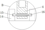
fig. 3 is an enlarged schematic view of a structure B in fig. 1 of a face image acquisition device according to an embodiment of the present invention;
fig. 4 is a schematic side view of a face image acquisition device according to an embodiment of the present invention;
fig. 5 is a schematic front view of a face image acquisition device according to an embodiment of the present invention.
In the drawings, the components represented by the respective reference numerals are listed below:
1. a base; 2. a support bar; 3. a computer; 4. an outer rod; 5. a slider; 6. a protective clamping plate; 7. an inner rod; 8. a camera; 9. a mounting seat; 10. a movable groove; 11. a spring; 12. connecting blocks; 13. a limiting block; 14. a fixed block; 15. a screw; 16. and a screw hole.
Detailed Description
The principles and features of the present invention are described below in conjunction with the accompanying fig. 1-5, which are provided as examples to illustrate the utility model and not to limit the scope of the utility model. The utility model is described in more detail in the following paragraphs by way of example with reference to the accompanying drawings. Advantages and features of the present invention will become apparent from the following description and from the claims. It is to be noted that the drawings are in a very simplified form and are not to precise scale, which is merely for the purpose of facilitating and distinctly claiming the embodiments of the present invention.
It will be understood that when an element is referred to as being "secured to" another element, it can be directly on the other element or intervening elements may also be present. When a component is referred to as being "connected" to another component, it can be directly connected to the other component or intervening components may also be present. When a component is referred to as being "disposed on" another component, it can be directly on the other component or intervening components may also be present. The terms "vertical," "horizontal," "left," "right," and the like as used herein are for illustrative purposes only.
Unless defined otherwise, all technical and scientific terms used herein have the same meaning as commonly understood by one of ordinary skill in the art to which this invention belongs. The terminology used in the description of the utility model herein is for the purpose of describing particular embodiments only and is not intended to be limiting of the utility model. As used herein, the term "and/or" includes any and all combinations of one or more of the associated listed items.
As shown in fig. 1 to 5, the utility model provides a human face image acquisition device, which comprises a computer 3, an outer rod 4, an inner rod 7, a fixed block 14 and a movable groove 10, wherein a protection clamping plate 6 is symmetrically arranged on the back surface of the upper end of the computer 3, the computer 3 is commonly called a computer, is a modern electronic computer 3 for high-speed calculation, can perform numerical calculation and logic calculation, and also has a memory function. The intelligent electronic device is a modern intelligent electronic device capable of automatically processing mass data at high speed according to program operation, an outer rod 4 is movably arranged on the back of a computer 3, a screw rod 15 is connected to the lower end of the outer rod 4 in a threaded mode, fixed blocks 14 are symmetrically arranged on the back of the lower end of the computer 3, two ends of the screw rod 15 are arranged on one side of the fixed blocks 14, and an inner rod 7 is arranged inside the outer rod 4 in a sliding mode.
The upper end of the inner rod 7 is provided with a camera 8, the camera 8 generally has the basic functions of video shooting, transmission, static image capture and the like, after the camera acquires images by means of a lens, the photosensitive component circuit and the control component in the camera 8 process the image and convert the image into a digital signal which can be recognized by a computer, and transmits the digital signal to the computer 3, the outer wall of the inner rod 7, which is different from the upper end and the lower end, is provided with a movable groove 10 at equal intervals, a spring 11 is arranged in the movable groove 10, one end of the spring 11, which faces the opening of the movable groove 10, is connected with a connecting block 12, one side of the connecting block 12, which is far away from the inner rod 7, is connected with a limiting block 13, the limiting block 13 can move in the movable groove 10 through the spring 11, when the inner rod 7 ascends from the inside of the outer rod 4, the limiting block 13 can clamp the inner rod 7, the inner rod 7 is prevented from falling back into the outside of the outer rod 4, and meanwhile, the height of the camera 8 can be adjusted by workers through the limiting blocks 13 at different positions.
Preferably, the relative one side of protection cardboard 6 is the design of recess form, and protection cardboard 6 can protect camera 8 after accomodating through the recess, and outer pole 4 takes place to rotate when avoiding idle camera 8, prevents that outer pole 4 from driving camera 8 and rotates, effectively protects camera 8 simultaneously, can avoid camera 8 to receive external striking and take place to damage.
Preferably, the inside slidable mounting of outer pole 4 has slider 5, and the lower extreme of interior pole 7 is installed in the upper surface of slider 5, and interior pole 7 accessible slider 5 carries out the steady slip, and slider 5 can prevent that interior pole 7 from droing from outer pole 4 simultaneously, avoids outer pole 4 and interior pole 7 to take place to separate.
Preferably, screw 16 has been seted up to the lower extreme outer wall of outer pole 4, and 15 threaded connection of screw rod have 16 inside of screw, screw rod 15 and 16 looks adaptations of screw for the staff can rotate outer pole 4 in a flexible way, and threaded connection has the resistance simultaneously, makes outer pole 4 can't rotate under the condition that does not receive external force, has effectively protected camera 8.
Preferably, the one end that spring 11 deviates from the activity groove 10 opening part is connected with mount pad 9, mount pad 9 is installed in the inner wall of activity groove 10, 9 stable installations of spring 11 accessible mount pads are inside activity groove 10, take place the bending when avoiding compression spring 11 and lead to the unable reseing of spring 11, can avoid spring 11 direct and activity groove 10 inner wall contact simultaneously, prevent that spring 11 from compressing repeatedly and kick-backing time and activity groove 10 inner wall emergence friction, avoid spring 11 to receive wearing and tearing to take place the fracture.
Preferably, stopper 13 and the opening part looks adaptation of activity groove 10, and stopper 13 deviates from the one end of outer pole 4 and is radius angle process design, the staff can extrude stopper 13, insert the inside of outer pole 4 with interior pole 7, simultaneously when staff's lifting interior pole 7, the stopper 13 of radius angle can receive the extrusion of outer pole 4 and then crowd stopper 13 into the inside of activity groove 10, make interior pole 7 can go up and down in a flexible way outside 4, avoid stopper 13 to block interior pole 7 in the inside of outer pole 4.
Preferably, bracing piece 2 is installed to computer 3's lower extreme, and bracing piece 2 can support computer 3, increases computer 3's height, and the staff of being convenient for official working, base 1 is installed to bracing piece 2's lower extreme, and the area of contact of base 1 multiplicable computer 3 and desktop has effectively improved computer 3's stability, avoids computer 3 to receive the collision and takes place to empty.
The specific working principle and the using method of the utility model are as follows: the device is connected with an external power supply, after an operator lifts the inner rod 7, the spring 11 compressed in the movable groove 10 ejects the limiting block 13, the limiting block 13 is clamped at the upper end of the outer rod 4, the inner rod 7 is fixed at a certain height, the camera 8 extends out of the protective clamping plate 6, the identity of the face information collected by the hotel guests can be conveniently identified through the camera 8, the collected images are transmitted to the computer 3 for detection and identification, the outer rod 4 can be rotated for guests with different heights, the angle of the camera 8 can be adjusted, the camera 8 can collect the face information for guests with different heights, the camera 8 is supported through the outer rod 4 and the inner rod 7, the condition that the operator holds the camera 8 by hand is avoided, the labor intensity of the operator is reduced, the camera 8 is prevented from falling from a desktop to the ground, and the damage of the camera 8 is avoided, when the staff accomodate the device, manual extrusion pushes stopper 13 inside movable groove 10 can accomodate interior pole 7 into the inside of outer pole 4, can block into the inside of protection cardboard 6 with camera 8 simultaneously, has effectively protected camera 8, has greatly improved the practicality of device.
The foregoing is merely a preferred embodiment of the utility model and is not intended to limit the utility model in any manner; the present invention may be readily implemented by those of ordinary skill in the art as illustrated in the accompanying drawings and described above; however, those skilled in the art should appreciate that they can readily use the disclosed conception and specific embodiments as a basis for designing or modifying other structures for carrying out the same purposes of the present invention without departing from the scope of the utility model as defined by the appended claims; meanwhile, any changes, modifications, and evolutions of the equivalent changes of the above embodiments according to the actual techniques of the present invention are still within the protection scope of the technical solution of the present invention.
Claims (7)
1. A human face image acquisition device is characterized in that: comprises a computer (3), an outer rod (4), an inner rod (7), a fixed block (14) and a movable groove (10), wherein a protective clamping plate (6) is symmetrically installed on the back of the upper end of the computer (3), the outer rod (4) is movably arranged on the back of the computer (3), a screw rod (15) is connected with the lower end of the outer rod (4) in a threaded manner, the fixed block (14) is symmetrically installed on the back of the lower end of the computer (3), the two ends of the screw rod (15) are installed on one side of the fixed block (14), the inner rod (7) is slidably installed inside the outer rod (4), a camera (8) is arranged on the upper end of the inner rod (7), the movable groove (10) is formed in the outer wall of the inner rod (7) in an equal distance different from the upper end to the lower end, a spring (11) is arranged inside the movable groove (10), one end of the spring (11) facing the opening of the movable groove (10) is connected with a connecting block (12), one side of the connecting block (12) departing from the inner rod (7) is connected with a limiting block (13).
2. The human face image acquisition device according to claim 1, characterized in that: the opposite side of the protection clamping plate (6) is designed in a groove shape.
3. The human face image acquisition device according to claim 1, characterized in that: the inner side of the outer rod (4) is provided with a sliding block (5) in a sliding mode, and the lower end of the inner rod (7) is arranged on the upper surface of the sliding block (5).
4. The human face image acquisition device according to claim 1, characterized in that: the outer rod (4) is characterized in that the outer wall of the lower end of the outer rod is provided with a screw hole (16), and the screw rod (15) is in threaded connection with the inside of the screw hole (16).
5. The human face image acquisition device according to claim 1, characterized in that: one end of the spring (11) departing from the opening of the movable groove (10) is connected with a mounting seat (9), and the mounting seat (9) is mounted on the inner wall of the movable groove (10).
6. The human face image acquisition device according to claim 1, characterized in that: the limiting block (13) is matched with the opening of the movable groove (10), and one end of the limiting block (13) deviating from the outer rod (4) is designed by a rounding process.
7. The human face image acquisition device according to claim 1, characterized in that: the lower extreme of computer (3) is installed bracing piece (2), base (1) is installed to the lower extreme of bracing piece (2).
Priority Applications (1)
| Application Number | Priority Date | Filing Date | Title |
|---|---|---|---|
| CN202123002025.XU CN216408496U (en) | 2021-12-02 | 2021-12-02 | Face image acquisition equipment |
Applications Claiming Priority (1)
| Application Number | Priority Date | Filing Date | Title |
|---|---|---|---|
| CN202123002025.XU CN216408496U (en) | 2021-12-02 | 2021-12-02 | Face image acquisition equipment |
Publications (1)
| Publication Number | Publication Date |
|---|---|
| CN216408496U true CN216408496U (en) | 2022-04-29 |
Family
ID=81305728
Family Applications (1)
| Application Number | Title | Priority Date | Filing Date |
|---|---|---|---|
| CN202123002025.XU Active CN216408496U (en) | 2021-12-02 | 2021-12-02 | Face image acquisition equipment |
Country Status (1)
| Country | Link |
|---|---|
| CN (1) | CN216408496U (en) |
Cited By (1)
| Publication number | Priority date | Publication date | Assignee | Title |
|---|---|---|---|---|
| CN111582112A (en) * | 2020-04-29 | 2020-08-25 | 重庆工程职业技术学院 | Working equipment and working method for screening abnormal personnel aiming at dense people |
-
2021
- 2021-12-02 CN CN202123002025.XU patent/CN216408496U/en active Active
Cited By (1)
| Publication number | Priority date | Publication date | Assignee | Title |
|---|---|---|---|---|
| CN111582112A (en) * | 2020-04-29 | 2020-08-25 | 重庆工程职业技术学院 | Working equipment and working method for screening abnormal personnel aiming at dense people |
Similar Documents
| Publication | Publication Date | Title |
|---|---|---|
| CN211928594U (en) | Self-service temperature measurement system and device thereof | |
| CN216408496U (en) | Face image acquisition equipment | |
| CN108805109B (en) | Motion data capturing and displaying system | |
| CN110995808A (en) | Power grid infrastructure site safety dynamic management and control system based on ubiquitous power Internet of things | |
| CN211232133U (en) | Face recognition device | |
| CN107180458A (en) | A kind of cabinet with face recognition function | |
| CN211911585U (en) | Intelligent wrist body temperature measuring system | |
| CN113290400A (en) | Protective device for processing machine tool | |
| CN208335321U (en) | A kind of gate inhibition's recognition of face all-in-one machine | |
| CN215730316U (en) | Teaching training platform capable of adjusting height and angle to perform image recognition | |
| CN212960812U (en) | Intelligent screen cabinet | |
| CN109917562A (en) | The intelligent glasses of secondary injury after a kind of falling-resistant for intelligent medical treatment | |
| CN211019007U (en) | Identity verification equipment based on face-face recognition | |
| CN111368655B (en) | Automatic marking device and method for counting passenger flow based on face recognition | |
| CN113044227A (en) | Unmanned aerial vehicle remote sensing device for surveying and mapping engineering that protecting effect is good | |
| CN211653682U (en) | Face recognition device capable of automatically adjusting recognition height | |
| CN209746568U (en) | Identity verification device based on face recognition | |
| CN217356347U (en) | Novel face identification all-in-one | |
| CN211749578U (en) | Wisdom body-building pavement equipment | |
| CN220773806U (en) | Physical speed testing device | |
| CN215679384U (en) | Face recognition system | |
| CN210955124U (en) | Face recognition information acquisition device | |
| CN216952298U (en) | Authentication device | |
| CN206574093U (en) | Limit protection component for iris identification device | |
| CN216719136U (en) | Support arrangement of image acquisition equipment for face identification |
Legal Events
| Date | Code | Title | Description |
|---|---|---|---|
| GR01 | Patent grant | ||
| GR01 | Patent grant |