CN216395959U - Concrete aggregate proportioning device for constructional engineering construction - Google Patents
Concrete aggregate proportioning device for constructional engineering construction Download PDFInfo
- Publication number
- CN216395959U CN216395959U CN202123001350.4U CN202123001350U CN216395959U CN 216395959 U CN216395959 U CN 216395959U CN 202123001350 U CN202123001350 U CN 202123001350U CN 216395959 U CN216395959 U CN 216395959U
- Authority
- CN
- China
- Prior art keywords
- stirring
- wall
- fixedly connected
- motor
- agitator
- Prior art date
- Legal status (The legal status is an assumption and is not a legal conclusion. Google has not performed a legal analysis and makes no representation as to the accuracy of the status listed.)
- Active
Links
Images


Abstract
The utility model relates to the field of constructional engineering, in particular to a concrete aggregate proportioning device for constructional engineering construction, which comprises a motor, wherein a stirring assembly is arranged at the lower end of the motor, a discharge pipe is arranged at the lower end of the stirring assembly, two discharge grooves are fixedly connected to the inner wall of the discharge pipe, sliding blocks are connected to the inner wall of the discharge grooves in a sliding manner, an annular rotating handle is sleeved on the surface of the discharge pipe, the inner wall of the annular rotating handle is fixedly connected with one end of each sliding block, and a transmission assembly is arranged on one side of the stirring assembly; through setting up the stirring subassembly, can stir and turn to agitator inside under the combined action of the board that turns, stirring piece and the pole that turns over, for the single stirring mode of traditional apparatus, reached and to have stirred bottom sedimentary material to the middle part to reduce the material deposit and strengthen the effect of mixing), and then through the cooperation stirring of turning, make its mixed more abundant.
Description
Technical Field
The utility model relates to the field of constructional engineering, in particular to a concrete aggregate proportioning device for constructional engineering construction.
Background
The concrete is an artificial stone which is formed by solidifying a cementing material after mixing the cementing material, water and aggregate according to a proper proportion, stirring and pouring. According to the difference of cementing materials, the concrete can be divided into cement concrete, gypsum concrete, asphalt concrete and the like. The concrete is usually called cement concrete which takes cement as a cementing material and sand and stone as aggregate.
The existing aggregate proportioning device has the advantages that in the mixing process, due to the single mixing mode, part of materials can be mixed at dead angles in the mixing process, the mixing effect of the materials in the mixing device is poor, and therefore, the concrete aggregate proportioning device for building engineering construction is provided by the technical personnel in the field to solve the problems in the background technology.
SUMMERY OF THE UTILITY MODEL
The utility model aims to solve the problems, and provides a concrete aggregate proportioning device for construction engineering, which solves the problem that the mixing effect is poor due to deposition in a mixing device because the mixing mode is single.
The utility model realizes the aim through the following technical scheme, and the concrete aggregate proportioning device for the construction of the building engineering comprises a motor, wherein the lower end of the motor is provided with a stirring assembly, the lower end of the stirring assembly is provided with a discharge pipe, the inner wall of the discharge pipe is fixedly connected with two discharge grooves, the inner walls of the discharge grooves are connected with sliding blocks in a sliding manner, the surface of the discharge pipe is sleeved with an annular rotating handle, the inner wall of the annular rotating handle is fixedly connected with one end of the sliding block, and one side of the stirring assembly is provided with a transmission assembly;
the stirring subassembly includes agitator and square strip, the upper end of agitator and the lower extreme fixed connection of motor, the inner wall and the motor output shaft of square strip rotate to be connected, the inner wall of agitator is provided with quantity and is two the ring rack, two the meshing is connected with quantity between the ring rack and is two the transmitting gear, one side fixedly connected with dwang of transmitting gear, the other end of dwang rotates and connects in one side of square strip, the fixed surface of dwang is connected with evenly distributed's the board that turns over.
Preferably, the lower end is fixedly connected with the circular rack on the inner wall of the stirring barrel, the upper end is fixedly connected with the connecting frame which is uniformly distributed on the upper end of the circular rack, and the other end of the connecting frame is fixedly connected with the output shaft of the motor.
Preferably, the lower extreme fixedly connected with quantity of square strip is two and stirs the piece, the lower extreme of stirring the piece and the interior diapire sliding connection of agitator, the surperficial sliding connection of square strip has square snap ring, the surperficial fixedly connected with quantity of square snap ring is two and turns over the pole.
Preferably, the surface of dwang is rotated and is connected with the rotation plectane, the lower extreme that rotates the plectane rotates with the inner diapire of agitator and is connected, the fixed plectane of inner wall fixedly connected with of agitator, the groove that floats has been seted up to the inner wall of fixed plectane, the other end of the pole that turns over and the inner wall sliding connection in groove that floats.
Preferably, the transmission assembly comprises a conveying pipe, the conveying pipe is communicated with the surface of the stirring barrel, one end of the conveying pipe penetrates through the stirring barrel and extends to the inside of the stirring barrel, the inner wall of the conveying pipe is rotatably connected with an auger plate, and the inner edge of the auger plate is fixedly connected with a conveying shaft.
Preferably, the transmission assembly further comprises a connecting plate, the connecting plate is fixedly connected to the inner top wall of the stirring barrel, the surface of the conveying shaft is rotatably connected with the inner wall of the connecting plate, one end of the conveying shaft is fixedly connected with a bevel gear with an output shaft of the motor, and the bevel gears are meshed and connected.
The utility model has the beneficial effects that: through setting up the stirring subassembly, can stir and turn to agitator inside under the combined action of the board that turns, stirring piece and the pole that turns over, for the single stirring mode of traditional apparatus, reached and to have stirred bottom sedimentary material to the middle part to reduce the material deposit and strengthen the effect of mixing), and then through the cooperation stirring of turning, make its mixed more abundant.
Drawings
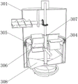
FIG. 1 is a schematic structural view of the present invention;
FIG. 2 is a schematic view of the connection of the auger plate to the transport shaft according to the present invention;
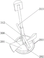
FIG. 3 is a schematic view of the connection between the rotating rod and the flipping board according to the present invention;
FIG. 4 is a schematic view of the connection between the circular rack and the rotating gear according to the present invention;
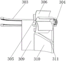
fig. 5 is a schematic view of the connection between the square snap ring and the flipping bar according to the present invention.
In the figure: 1. a motor; 2. a discharge pipe; 201. a discharge chute; 202. a slider; 203. a ring-shaped rotating handle; 3. a stirring assembly; 301. a stirring barrel; 302. a connecting frame; 303. a circular rack; 304. a rotating gear; 305. rotating the rod; 306. turning the plate; 307. square bars; 308. a stirring block; 309. rotating the circular plate; 310. fixing the circular plate; 311. a floating tank; 312. a square snap ring; 313. turning over a rod; 4. a transmission assembly; 401. a delivery pipe; 402. a twisted plate; 403. a delivery shaft; 404. a connecting plate; 405. a bevel gear.
Detailed Description
The technical solutions in the embodiments of the present invention will be clearly and completely described below with reference to the drawings in the embodiments of the present invention, and it is obvious that the described embodiments are only a part of the embodiments of the present invention, and not all of the embodiments. All other embodiments, which can be derived by a person skilled in the art from the embodiments given herein without making any creative effort, shall fall within the protection scope of the present invention.
In the specific implementation: as shown in fig. 1-5, a concrete aggregate proportioning device for building engineering construction comprises a motor 1, a stirring component 3 is arranged at the lower end of the motor 1, a discharge pipe 2 is arranged at the lower end of the stirring component 3, two discharge grooves 201 are fixedly connected to the inner wall of the discharge pipe 2, sliding blocks 202 are slidably connected to the inner wall of the discharge grooves 201, an annular rotating handle 203 is sleeved on the surface of the discharge pipe 2, the inner wall of the annular rotating handle 203 is fixedly connected with one end of the sliding block 202, a transmission component 4 is arranged at one side of the stirring component 3, the stirring component 3 comprises a stirring barrel 301 and square bars 307, the upper end of the stirring barrel 301 is fixedly connected with the lower end of the motor 1, the inner wall of the square bars 307 is rotatably connected with an output shaft of the motor 1, two circular racks 303 are arranged on the inner wall of the stirring barrel 301, two rotating gears 304 are engaged and connected between the two circular racks 303, one side of the rotating gear 304 is fixedly connected with a rotating rod 305, the other end of the rotating rod 305 is rotatably connected with one side of a square bar 307, the surface of the rotating rod 305 is fixedly connected with a turning plate 306 which is uniformly distributed, the motor 1 rotates to drive the stirring component 3 to stir the concrete aggregate in the stirring component, meanwhile, the motor 1 rotates to drive the transmission component 4 to transmit the concrete aggregate which is matched in the stirring component to the stirring component 3, the stirring component 3 discharges the fully stirred material through the discharge pipe 2 after running and stirring, an operator can drive the sliding block 202 to slide in the discharge groove 201 to seal or discharge the discharge pipe 2 by rotating the annular rotating handle 203, when the motor 1 rotates, the two annular racks 303 are driven to run to drive the rotating gear 304 to perform meshing motion, and the rotating gear 304 can drive the rotating rod 305 to rotate when moving, the turning plate 306 can rotate along with the turning rod 305 while the turning rod 305 rotates at one side of the square bar 307, so that the materials in the stirring barrel 301 can be turned and stirred;
as shown in fig. 3, 4 and 5, the lower circular rack 303 is fixedly connected to the inner wall of the stirring barrel 301, the upper end of the upper circular rack 303 is fixedly connected with the evenly distributed connecting frames 302, the other end of the connecting frame 302 is fixedly connected to the output shaft of the motor 1, the lower circular rack 303 is fixedly connected to the inner wall of the stirring barrel 301, so that the motor 1 can drive the upper circular rack 303 to rotate when rotating, the upper circular rack 303 further drives the rotating gear 304 to move on the surface of the lower circular rack 303 when rotating, further the upper circular rack 303 can drive the rotating gear 304 to synchronously rotate when moving, the lower end of the square bar 307 is fixedly connected with two stirring blocks 308, the lower end of the stirring block 308 is slidably connected with the inner bottom wall of the stirring barrel 301, the surface of the square bar 307 is slidably connected with the square snap ring 312, the surface of the square snap ring 312 is fixedly connected with two turning rods 313, the rotating rod 305 can drive the square bar 307 to rotate when rotating, the square bar 307 can drive the two stirring blocks 308 with fixedly connected lower ends to rotate when rotating, the two stirring blocks 308 are inclined surfaces at one side, the stirring block 308 with a triangular cross section and a straight surface at one side, when the stirring block 308 slides with the inner bottom wall of the stirring barrel 301, the bottom of the stirring barrel 301 is heavier, the inclined surfaces of the stirring blocks 308 are pushed to ascend and move along the inclined surfaces of the stirring blocks 308, the materials with larger bottom weight and larger weight are lifted to the middle area of the stirring barrel 301 through the inclined surfaces of the stirring blocks 308, the stirring plates 306 are matched to stir so as to be more fully mixed, the surface of the rotating rod 305 is rotatably connected with the rotating circular plate 309, the lower end of the rotating circular plate 309 is rotatably connected with the inner bottom wall of the stirring barrel 301, the inner wall of the stirring barrel 301 is fixedly connected with the fixed circular plate 310, the inner wall of the fixed circular plate 310 is provided with the floating groove 311, the other end of the turning rod 313 is connected with the inner wall of the floating groove 311 in a sliding manner, when the rotating rod 305 rotates, the rotating circular plate 309 is driven to rotate on the inner bottom wall of the stirring barrel 301 during movement, and further, materials stirred inside can be prevented from invading into the components and interfering with the operation of the components, the inner bottom wall of the inner wall of the stirring barrel 301 is fixedly connected with the fixed circular plate 310, the floating groove 311 is formed in the inner wall of the fixed circular plate 310, when the turning rod 313 rotates along with the square clamping ring 312 along with the square strip 307, the other end of the turning rod 313 can drive the square clamping ring 312 to float up and down under the action of the floating groove 311, and the materials are turned over, so that the materials are mixed more uniformly;
as shown in fig. 2, 3 and 4, the transmission assembly 4 includes a transmission pipe 401, the transmission pipe 401 is communicated with the surface of the stirring barrel 301, one end of the transmission pipe 401 penetrates through the stirring barrel 301 and extends into the stirring barrel 301, the inner wall of the transmission pipe 401 is rotatably connected with an auger plate 402, the inner edge of the auger plate 402 is fixedly connected with a transmission shaft 403, when the output shaft rotates, the auger plate 402 is driven to rotate, the auger plate 402 enables the material in the transmission pipe 401 to be transmitted into the stirring barrel 301, so that the material can be continuously supplemented and transmitted into the stirring barrel 301 under the rotation action of the transmission shaft 403, the transmission assembly 4 further includes a connection plate 404, the connection plate 404 is fixedly connected to the inner top wall of the stirring barrel 301, the surface of the transmission shaft 403 is rotatably connected with the inner wall of the connection plate 404, one end of the transmission shaft 403 and the output shaft of the motor 1 are both fixedly connected with a bevel gear 405, two bevel gears 405 meshing connect, when motor 1 moves, motor 1's output shaft surface is fixed with bevel gear 405, and then can be so that in motor 1 output shaft pivoted, can make through bevel gear 405 carry axle 403 and motor 1 output shaft to carry out synchronous rotation, and then can make when motor 1 rotates, the accessible drives and carries axle 403 to rotate synchronous, makes the material carry to agitator 301 inside in conveyer pipe 401 through the rotation of carrying axle 403.
When the utility model is used, the motor 1 rotates to drive the connecting frame 302 and the bevel gear 405 to synchronously rotate, the bevel gear 405 drives the auger plate 402 to rotate on the inner wall of the conveying pipe 401 through the conveying shaft 403, the materials to be mixed are conveyed into the stirring barrel 301 through the conveying pipe 401, the connecting rod is fixedly connected with the upper end annular rack, the upper end annular rack drives the rotating gear 304 to move on the lower end annular rack 303 along with the rotation of the motor 1, the turning plate 306 fixedly connected with the surface of the upper end annular rack is driven to move through the rotating rod 305, meanwhile, the lower end of the square bar 307 is fixedly connected with the stirring block 308 to stir the deposited materials to the middle part of the stirring barrel 301, the required stirring materials are fully mixed through the turning plate 306, the rotating rod 305 drives the rotating circular plate 309 to rotate, the rotating circular plate 309 can prevent the internal mixed materials from entering between the rotating annular rack 303 and the rotating gear 304 to prevent the parts from being blocked, the inner bottom wall of the mixing tank 301 is fixedly connected, a fixed circular plate 310 is provided with a floating groove 311, a square snap ring 312 drives a turning rod 313 to fully mix the mixed materials in the floating groove 311 through the turning rod 313.
It will be evident to those skilled in the art that the utility model is not limited to the details of the foregoing illustrative embodiments, and that the present invention may be embodied in other specific forms without departing from the spirit or essential attributes thereof. The present embodiments are therefore to be considered in all respects as illustrative and not restrictive, the scope of the utility model being indicated by the appended claims rather than by the foregoing description, and all changes which come within the meaning and range of equivalency of the claims are therefore intended to be embraced therein. Any reference sign in a claim should not be construed as limiting the claim concerned.
Furthermore, it should be understood that although the present description refers to embodiments, not every embodiment may contain only a single embodiment, and such description is for clarity only, and those skilled in the art should integrate the description, and the embodiments may be combined as appropriate to form other embodiments understood by those skilled in the art.
Claims (6)
1. The utility model provides a concrete aggregate proportioning device for building engineering construction, includes motor (1), its characterized in that: the stirring device is characterized in that a stirring assembly (3) is arranged at the lower end of the motor (1), a discharge pipe (2) is arranged at the lower end of the stirring assembly (3), two discharge grooves (201) are fixedly connected to the inner wall of the discharge pipe (2), sliding blocks (202) are connected to the inner wall of each discharge groove (201) in a sliding mode, an annular rotating handle (203) is sleeved on the surface of the discharge pipe (2), the inner wall of the annular rotating handle (203) is fixedly connected with one end of each sliding block (202), and a transmission assembly (4) is arranged on one side of the stirring assembly (3);
stirring subassembly (3) are including agitator (301) and square strip (307), the upper end of agitator (301) and the lower extreme fixed connection of motor (1), the inner wall of square strip (307) rotates with motor (1) output shaft to be connected, the inner wall of agitator (301) is provided with quantity and is ring rack (303) two, two the meshing is connected with quantity between ring rack (303) and is two rolling gear (304), one side fixedly connected with dwang (305) of rolling gear (304), the other end of dwang (305) rotates and connects in one side of square strip (307), the fixed surface of dwang (305) is connected with evenly distributed's board (306) that turns over.
2. The concrete aggregate proportioning device for constructional engineering construction of claim 1, wherein: the lower extreme ring rack (303) fixed connection is in the inner wall of agitator (301), and the upper end fixedly connected with evenly distributed's of ring rack (303) link (302), the other end fixed connection of link (302) is in motor (1) output shaft.
3. The concrete aggregate proportioning device for constructional engineering construction according to claim 2, characterized in that: the lower extreme fixedly connected with quantity of square strip (307) is stirring piece (308) two, the lower extreme of stirring piece (308) and the interior diapire sliding connection of agitator (301), the surperficial sliding connection of square strip (307) has square snap ring (312), the fixed surface of square snap ring (312) is connected with quantity and is two tie rod (313) that turns over.
4. The concrete aggregate proportioning device for constructional engineering construction of claim 3, characterized in that: the surface of dwang (305) rotates and is connected with rotation plectane (309), the lower extreme of rotation plectane (309) rotates with the inner diapire of agitator (301) and is connected, the fixed plectane (310) of inner wall fixedly connected with of agitator (301), floating groove (311) has been seted up to the inner wall of fixed plectane (310), the other end of turnover pole (313) and the inner wall sliding connection of floating groove (311).
5. The concrete aggregate proportioning device for constructional engineering construction of claim 1, wherein: the transmission assembly (4) comprises a transmission pipe (401), the transmission pipe (401) is communicated with the surface of the stirring barrel (301), one end of the transmission pipe (401) penetrates through the stirring barrel (301) and extends to the inside of the stirring barrel (301), the inner wall of the transmission pipe (401) is rotatably connected with an auger plate (402), and the inner edge of the auger plate (402) is fixedly connected with a transmission shaft (403).
6. The concrete aggregate proportioning device for constructional engineering construction of claim 5, wherein: the transmission assembly (4) further comprises a connecting plate (404), the connecting plate (404) is fixedly connected to the inner top wall of the stirring barrel (301), the surface of the conveying shaft (403) is rotatably connected with the inner wall of the connecting plate (404), one end of the conveying shaft (403) is fixedly connected with a bevel gear (405) with an output shaft of the motor (1), and the bevel gears (405) are meshed and connected.
Priority Applications (1)
| Application Number | Priority Date | Filing Date | Title |
|---|---|---|---|
| CN202123001350.4U CN216395959U (en) | 2021-12-01 | 2021-12-01 | Concrete aggregate proportioning device for constructional engineering construction |
Applications Claiming Priority (1)
| Application Number | Priority Date | Filing Date | Title |
|---|---|---|---|
| CN202123001350.4U CN216395959U (en) | 2021-12-01 | 2021-12-01 | Concrete aggregate proportioning device for constructional engineering construction |
Publications (1)
| Publication Number | Publication Date |
|---|---|
| CN216395959U true CN216395959U (en) | 2022-04-29 |
Family
ID=81304502
Family Applications (1)
| Application Number | Title | Priority Date | Filing Date |
|---|---|---|---|
| CN202123001350.4U Active CN216395959U (en) | 2021-12-01 | 2021-12-01 | Concrete aggregate proportioning device for constructional engineering construction |
Country Status (1)
| Country | Link |
|---|---|
| CN (1) | CN216395959U (en) |
-
2021
- 2021-12-01 CN CN202123001350.4U patent/CN216395959U/en active Active
Similar Documents
| Publication | Publication Date | Title |
|---|---|---|
| CN107160564A (en) | A kind of liftable building concrete mixer of puddler | |
| CN111531717B (en) | Cement concrete preparation system and preparation method thereof | |
| CN210045192U (en) | Planetary stirring device | |
| CN108297276A (en) | A kind of stirring of concrete and pour integration apparatus | |
| CN215624178U (en) | Prevent concrete mortar storage tank of ejection of compact of being convenient for of stifled type | |
| CN208068563U (en) | A kind of stirring of concrete and pour integration apparatus | |
| CN216395959U (en) | Concrete aggregate proportioning device for constructional engineering construction | |
| CN212707384U (en) | Concrete mixing device is used in civil engineering construction | |
| CN107175768A (en) | A kind of efficient batching plant | |
| CN113232159B (en) | Commercial concrete mixing and conveying integrated system | |
| CN212978792U (en) | Concrete mixer capable of stirring uniformly | |
| CN205630988U (en) | Raw material mixing device for brickmaking | |
| CN112571621B (en) | Concrete preparation method | |
| CN210969410U (en) | Lime agitating unit is used to building decoration of misce bene | |
| CN211518004U (en) | Aerated brick agitating unit convenient to clearance | |
| CN207930857U (en) | A kind of reinforced concrete sewer pipe production line | |
| CN216068042U (en) | Quick mixing device is used in anti-crack mortar production and processing | |
| CN216860154U (en) | Concrete mixing production facility for building engineering | |
| CN219726736U (en) | Cement premixing device | |
| CN215511696U (en) | Raw material conveying device for stirring premixed concrete | |
| CN218365646U (en) | Mortar stirring device | |
| CN204604601U (en) | A kind of concrete central mix plant | |
| CN217372866U (en) | Automatic concrete production device | |
| CN216941242U (en) | Aerated concrete block production line material mixing device of improvement | |
| CN217568452U (en) | Mixing arrangement is used in polycarboxylate water reducing agent processing |
Legal Events
| Date | Code | Title | Description |
|---|---|---|---|
| GR01 | Patent grant | ||
| GR01 | Patent grant |