CN216384592U - High-temperature oil type mold temperature controller - Google Patents
High-temperature oil type mold temperature controller Download PDFInfo
- Publication number
- CN216384592U CN216384592U CN202122766368.7U CN202122766368U CN216384592U CN 216384592 U CN216384592 U CN 216384592U CN 202122766368 U CN202122766368 U CN 202122766368U CN 216384592 U CN216384592 U CN 216384592U
- Authority
- CN
- China
- Prior art keywords
- pipeline
- oil
- output end
- temperature
- casing
- Prior art date
- Legal status (The legal status is an assumption and is not a legal conclusion. Google has not performed a legal analysis and makes no representation as to the accuracy of the status listed.)
- Active
Links
Images


Abstract
The utility model relates to the technical field of mold temperature controllers, in particular to a high-temperature oil type mold temperature controller which comprises a shell, wherein side protection plates are arranged on the side walls of the shell, a control panel is arranged on the front surface of the shell, a controller main body is arranged in the shell, an oil tank is arranged on one side of the controller main body, and a cooler is arranged on one side of the oil tank away from the controller main body.
Description
Technical Field
The utility model relates to the technical field of die temperature controllers, in particular to a high-temperature oil type die temperature controller.
Background
The oil type mould temperature controller in the market at present mainly comprises an oil tank, an expansion oil tank, an oil pump, a heating pipe, a cooling coil pipe, an oil outlet pipeline, an oil return pipeline, a cooling water inlet pipeline, a cooling water outlet pipeline and the like, when the oil tank works, heat conduction oil in the oil tank is conveyed to a mould by the oil pump through the oil outlet pipeline, the heat conduction oil after heat exchange with the mould returns to the oil tank through the oil return pipeline to form a circulating working loop, a temperature sensing element detects the temperature of the heat conduction oil and feeds back the temperature to a temperature controller, when the temperature of the heat conduction oil is lower than the set value of the temperature controller, the temperature controller outputs a signal to close the power supply of the heating pipe to start heating, when the temperature of the heat conduction oil is higher than the set value of the temperature controller, the temperature controller outputs a signal to disconnect the power supply of the heating pipe to stop heating, and simultaneously to open a cooling electromagnetic valve, external cooling water enters the cooling coil pipe to cool the heat conduction oil, and the process is repeated in such a way that the temperature of the heat conduction oil is maintained at the set value of the temperature controller, however, in the actual production process, the cooling water cooling efficiency is low, the temperature of the cooling oil can not be ensured within a controllable range for a long time, the cooling water cooling effect is not good, the production process is easy to stop, and the production efficiency is influenced.
SUMMERY OF THE UTILITY MODEL
The present invention is directed to a high temperature oil type mold temperature controller, which solves the above problems in the prior art.
In order to achieve the purpose, the utility model provides the following technical scheme:
the utility model provides a high temperature oil formula mould temperature controller, includes the casing, the side guard plate is all installed to the lateral wall of casing, the front of casing is provided with control panel, the inside of casing is provided with the controller main part, one side of controller main part is provided with the oil tank, one side that the controller main part was kept away from to the oil tank is provided with the cooler, the cooler includes compressor, heat exchanger, liquid storage pot, economic ware, filter, expansion valve, evaporimeter, vapour and liquid separator, water pump and outside water tank, the top of controller main part is and the inside that is located the casing is provided with heating element, the terminal surface of casing is provided with radiator fan, the back top-down of casing has set gradually oil pipe way and cooling water pipeline.
As a preferable scheme of the utility model, the end face of the shell is uniformly provided with heat dissipation holes, and the side wall of the side guard plate is uniformly provided with ventilation holes.
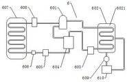
As a preferable scheme of the present invention, an output end of the compressor is connected to an input port of a heat exchanger through a pipeline, an output end of the heat exchanger is connected to a liquid storage tank through a pipeline, an output end of the liquid storage tank is connected to an economizer through a pipeline, a gas end of the economizer is connected to the compressor through a pipeline, a liquid end of the economizer is connected to a filter through a pipeline, an output end of the filter is connected to an expansion valve through a pipeline, the other end of the expansion valve is connected to an input end of an evaporator through a pipeline, an output end of the evaporator is connected to a gas-liquid separator through a pipeline, the evaporator is disposed inside the oil tank, an output end of the gas-liquid separator is connected to an input end of the compressor through a pipeline, a cooling chamber is disposed inside the heat exchanger, an input end of the water pump is connected to an external water tank through a pipeline, and an output end of the water pump is connected to the cooling chamber, the output end of the cooling chamber is connected with an external water tank.
In a preferred embodiment of the present invention, the heat exchanger and the evaporator are both copper bent tubes.
As a preferable scheme of the present invention, the oil line is connected to the controller main body and the oil tank through a pipe, and the cooling water line is connected to the cooler and the external water tank through a pipe.
As a preferable scheme of the present invention, the control panel is respectively connected to the controller main body, the cooler, the cooling fan and the heating assembly through wires, and the connection modes are all electrically connected.
Compared with the prior art, the utility model has the beneficial effects that:
1. according to the utility model, the evaporative cooling type cooler is arranged, the control panel is connected with the control panel through the lead, the control panel is used for detecting the temperature condition of the oil tank, when the high-temperature early warning is achieved, the cooler is started, the cooling liquid generated by the cooler enters the evaporator, the evaporator is arranged in the oil tank, the evaporator and the hot oil are directly subjected to heat exchange, the hot oil can be rapidly and continuously cooled, the traditional cooling water cooling is replaced, and the cooling efficiency is obviously improved.
2. According to the utility model, by arranging the cooling chamber, the external water tank continuously enters the cooling chamber to exchange heat with the heat exchanger, the design of the external water tank can be adjusted according to actual production requirements, and most production condition requirements can be met.
Drawings
FIG. 1 is a schematic structural view of the present invention;
FIG. 2 is a schematic view of the internal structure of the present invention;
fig. 3 is a schematic view of the structure of the cooler of the present invention.
In the figure: 1. a housing; 2. a side guard plate; 3. a control panel; 4. a controller main body; 5. an oil tank; 6. a cooler; 7. a heating assembly; 8. a heat radiation fan; 9. an oil pipeline; 10. a cooling water line; 101. heat dissipation holes; 201. a vent hole; 601. a compressor; 602. a heat exchanger; 603. a liquid storage tank; 604. an economizer; 605. a filter; 606. an expansion valve; 607. an evaporator; 608. a gas-liquid separator; 609. a water pump; 610. an external water tank; 6021. and a cooling chamber.
Detailed Description
The technical solutions in the embodiments of the present invention will be clearly and completely described below with reference to the embodiments of the present invention, and it is obvious that the described embodiments are only a part of the embodiments of the present invention, rather than all embodiments, and all other embodiments obtained by a person of ordinary skill in the art without any creative work based on the embodiments of the present invention belong to the protection scope of the present invention.
While several embodiments of the present invention will be described more fully hereinafter with reference to the accompanying drawings, in order to facilitate an understanding of the utility model, the utility model may be embodied in many different forms and should not be construed as limited to the embodiments set forth herein, but rather should be construed to provide a more complete disclosure of the utility model.
It will be understood that when an element is referred to as being "secured to" another element, it can be directly on the other element or intervening elements may also be present, that when an element is referred to as being "connected" to another element, it can be directly connected to the other element or intervening elements may also be present, and that the terms "vertical", "horizontal", "left", "right" and the like are used herein for descriptive purposes only.
Unless defined otherwise, all technical and scientific terms used herein have the same meaning as commonly understood by one of ordinary skill in the art to which this invention belongs, and the terms used herein in the specification of the present invention are for the purpose of describing particular embodiments only and are not intended to limit the present invention, and the term "and/or" as used herein includes any and all combinations of one or more of the associated listed items.
Referring to fig. 1-3, the present invention provides a technical solution:
a high-temperature oil type mold temperature controller comprises a shell 1, side protection plates 2 are mounted on the side walls of the shell 1, a control panel 3 is arranged on the front face of the shell 1, a controller main body 4 is arranged inside the shell 1, an oil tank 5 is arranged on one side of the controller main body 4, a cooler 6 is arranged on one side, away from the controller main body 4, of the oil tank 5, oil can be rapidly and effectively cooled by utilizing an evaporative cooling area, the cooler 6 comprises a compressor 601, a heat exchanger 602, a liquid storage tank 603, an economizer 604, a filter 605, an expansion valve 606, an evaporator 607, a gas-liquid separator 608, a water pump 609 and an external water tank 610, a heating assembly 7 is arranged above the controller main body 4 and inside the shell 1, and when the temperature in the oil tank 5 is low, the heating assembly 7 is used for heating the shell, a heat radiation fan 8 is arranged on the end face of the shell 1, and an oil pipeline 9 and a cooling water pipeline 10 are sequentially arranged on the back face of the shell 1 from top to bottom.
In the embodiment, referring to fig. 1 and fig. 3, the end surface of the housing 1 is uniformly provided with heat dissipation holes 101, the side wall of the side guard plate 2 is uniformly provided with vent holes 201, so as to enhance the heat dissipation function of the device, the output end of the compressor 601 is connected with the input port of the heat exchanger 602 through a pipeline, the compressor 601 converts low-temperature and low-pressure gaseous refrigerant into high-pressure and high-temperature gaseous refrigerant, the output end of the heat exchanger 602 is connected with the liquid storage tank 603 through a pipeline, the high-pressure refrigerant after heat exchange is condensed into liquid at normal temperature and enters the liquid storage tank 603, the output end of the liquid storage tank 603 is connected with the economizer 604 through a pipeline, the gaseous end of the economizer 604 is connected to the compressor 601 through a pipeline, the refrigerant enters the economizer 604 and then throttles, evaporates and absorbs heat, so that another part of the refrigerant is supercooled, the liquid end of the economizer 604 is connected with a filter 605 through a pipeline, and the output end of the filter 605 is connected with the expansion valve 606 through a pipeline, the medium-temperature high-pressure liquid refrigerant is throttled into low-temperature low-pressure wet steam, the other end of the expansion valve 606 is connected with the input end of the evaporator 607 through a pipeline, the output end of the evaporator 607 is connected with the gas-liquid separator 608 through a pipeline, the evaporator 607 is arranged inside the oil tank 5, hot oil in the oil tank 5 is rapidly cooled by the evaporator 607, the output end of the gas-liquid separator 608 is connected with the input end of the compressor 601 through a pipeline, the inside of the heat exchanger 602 is provided with a cooling chamber 6021, the input end of the water pump 609 is connected with the external water tank 610 through a pipeline, the output end of the water pump 609 is connected with the cooling chamber 6021, the output end of the cooling chamber 6021 is connected with the external water tank 610, and the refrigerant is subjected to heat exchange by cooling water of the external water tank 610.
In an embodiment, referring to fig. 1, fig. 2 and fig. 3, the heat exchanger 602 and the evaporator 607 are both copper bent pipes, the copper pipes have high thermal conductivity, thereby enhancing the heat exchange efficiency of the apparatus, the oil pipe 9 is respectively connected to the controller main body 4 and the oil tank 5 through pipes, the oil pipe 9 is provided with an oil outlet pipe and an oil return pipe for transporting oil therebetween to control the temperature of the mold, the cooling water pipe 10 is respectively connected to the cooler 6 and the external water tank 610 through pipes, and is used for connecting the external water tank 610 to continuously provide cooling water for the cooling chamber, the control panel 3 is respectively connected to the controller main body 4, the cooler 6, the cooling fan 8 and the heating assembly 7 through wires, and the connection modes are all electrical connections, the apparatus is centrally managed through the control panel 3, and the operation by a user is facilitated.
The working process of the utility model is as follows: firstly, an oil pipeline 9 is connected with a mold machine needing cooling, a cooling water pipeline 10 is connected with an external water tank 610, a control panel 3 is respectively connected with a controller main body 4, a cooler 6, a cooling fan 8 and a heating assembly 7 through leads, the connection modes are all electrically connected, centralized management is carried out on the device through the control panel 3, the operation of a user is facilitated, the control panel 3 always detects the oil temperature in an oil tank 5, if the oil temperature is lower than a low-temperature early warning value, the heating assembly 7 is started, a heating pipe in the heating assembly 7 carries out heating treatment on the oil tank 5 to enable the oil temperature to be higher than the low-temperature early warning value, if the oil temperature is higher than the high-temperature early warning value, the cooler 6 is started, a compressor 601 converts low-temperature and low-pressure gaseous refrigerants into high-temperature gaseous refrigerants, the high-pressure and high-temperature gaseous refrigerants enter a heat exchanger 602, a water pump 609 is started, the water pump 609 continuously conveys cooling water of the external water tank 610 into a cooling chamber 6021, namely, the heat exchange is carried out with high-pressure and high-temperature gaseous refrigerants, the high-pressure refrigerants are condensed into liquid at normal temperature after the heat exchange and enter a liquid storage tank 603, the output end of the liquid storage tank 603 is connected with an economizer 604 through a pipeline, the gaseous end of the economizer 604 is connected with a compressor 601 through a pipeline, the refrigerant throttles and evaporates to absorb heat after entering the economizer 604 so as to supercool the other part of the refrigerant, the liquid end of the economizer 604 is connected with a filter 605 through a pipeline, the output end of the filter 605 is connected with an expansion valve 606 through a pipeline to throttle the medium-temperature and high-pressure liquid refrigerants into low-temperature and low-pressure wet steam, the other end of the expansion valve 606 is connected with the input end of an evaporator 607 through a pipeline, the output end of the evaporator 607 is connected with a gas-liquid separator 608 through a pipeline, the evaporator 607 is arranged inside an oil tank 5, and the evaporator 607 is used for rapidly cooling hot oil in the oil tank 5, the output end of the gas-liquid separator 608 is connected to the input end of the compressor 601 through a pipeline, and the output end of the compressor 601 is connected to the input end of the heat exchanger 602 through a pipeline, so that hot oil in the oil tank 5 is cooled back and forth until the oil temperature is lower than the high-temperature early warning value.
Although embodiments of the present invention have been shown and described, it will be appreciated by those skilled in the art that changes, modifications, substitutions and alterations can be made in these embodiments without departing from the principles and spirit of the utility model, the scope of which is defined in the appended claims and their equivalents.
Claims (6)
1. The utility model provides a high temperature oil formula mould temperature controller, includes casing (1), its characterized in that: side guard plate (2) are all installed to the lateral wall of casing (1), the front of casing (1) is provided with control panel (3), the inside of casing (1) is provided with controller main part (4), one side of controller main part (4) is provided with oil tank (5), one side that controller main part (4) were kept away from in oil tank (5) is provided with cooler (6), cooler (6) are including compressor (601), heat exchanger (602), liquid storage pot (603), economic ware (604), filter (605), expansion valve (606), evaporimeter (607), vapour and liquid separator (608), water pump (609) and outside water tank (610), the top of controller main part (4) is and be located the inside of casing (1) and be provided with heating element (7), the terminal surface of casing (1) is provided with radiator fan (8), the back of casing (1) has set gradually oil pipeline (9) and cooling water pipeline (10) from top to bottom ).
2. The high-temperature oil type mold temperature controller according to claim 1, wherein: the terminal surface of casing (1) evenly is provided with louvre (101), the lateral wall of side guard plate (2) evenly is provided with ventilation hole (201).
3. The high-temperature oil type mold temperature controller according to claim 1, wherein: the output end of the compressor (601) is connected with the input port of the heat exchanger (602) through a pipeline, the output end of the heat exchanger (602) is connected with the liquid storage tank (603) through a pipeline, the output end of the liquid storage tank (603) is connected with the economizer (604) through a pipeline, the gaseous end of the economizer (604) is connected to the compressor (601) through a pipeline, the liquid end of the economizer (604) is connected with the filter (605) through a pipeline, the output end of the filter (605) is connected with the expansion valve (606) through a pipeline, the other end of the expansion valve (606) is connected with the input end of the evaporator (607) through a pipeline, the output end of the evaporator (607) is connected with the gas-liquid separator (608) through a pipeline, the evaporator (607) is arranged in the oil tank (5), and the output end of the gas-liquid separator (608) is connected with the input end of the compressor (601) through a pipeline, a cooling chamber (6021) is arranged inside the heat exchanger (602), the input end of the water pump (609) is connected with the external water tank (610) through a pipeline, the output end of the water pump (609) is connected with the cooling chamber (6021), and the output end of the cooling chamber (6021) is connected with the external water tank (610).
4. The high-temperature oil type mold temperature controller according to claim 3, wherein: the heat exchanger (602) and the evaporator (607) are both internally provided with copper bent pipes.
5. The high-temperature oil type mold temperature controller according to claim 3, wherein: the oil pipeline (9) is connected with the controller main body (4) and the oil tank (5) through pipelines respectively, and the cooling water pipeline (10) is connected with the cooler (6) and the external water tank (610) through pipelines respectively.
6. The high-temperature oil type mold temperature controller according to claim 3, wherein: the control panel (3) is respectively connected with the control machine main body (4), the cooler (6), the cooling fan (8) and the heating assembly (7) through leads, and the connection modes are all electrically connected.
Priority Applications (1)
| Application Number | Priority Date | Filing Date | Title |
|---|---|---|---|
| CN202122766368.7U CN216384592U (en) | 2021-11-12 | 2021-11-12 | High-temperature oil type mold temperature controller |
Applications Claiming Priority (1)
| Application Number | Priority Date | Filing Date | Title |
|---|---|---|---|
| CN202122766368.7U CN216384592U (en) | 2021-11-12 | 2021-11-12 | High-temperature oil type mold temperature controller |
Publications (1)
| Publication Number | Publication Date |
|---|---|
| CN216384592U true CN216384592U (en) | 2022-04-26 |
Family
ID=81250927
Family Applications (1)
| Application Number | Title | Priority Date | Filing Date |
|---|---|---|---|
| CN202122766368.7U Active CN216384592U (en) | 2021-11-12 | 2021-11-12 | High-temperature oil type mold temperature controller |
Country Status (1)
| Country | Link |
|---|---|
| CN (1) | CN216384592U (en) |
-
2021
- 2021-11-12 CN CN202122766368.7U patent/CN216384592U/en active Active
Similar Documents
| Publication | Publication Date | Title |
|---|---|---|
| CN103983013A (en) | Novel frostless air source heat pump water heater | |
| CN101294753B (en) | Inner circulation compound energy heat-supplying refrigeration technology and device | |
| CN203516008U (en) | Dual-recovery system for oil and gas heat | |
| CN213636112U (en) | Water chilling unit and energy storage system | |
| CN216384592U (en) | High-temperature oil type mold temperature controller | |
| CN211119798U (en) | Air conditioner air can automated inspection new trend system oil smoke all-in-one | |
| CN202063404U (en) | Multifunctional box of two uses of refrigeration and warm insulation of new high efficiency and utility type | |
| CN206670031U (en) | Electric heater | |
| US20220205699A1 (en) | Chiller and energy storage system | |
| CN115899646A (en) | Industrial high-temperature heat pump system | |
| CN201954832U (en) | Novel efficient and practical semiconductor refrigerating and heating box | |
| CN201497245U (en) | Small refrigerating equipment | |
| CN211352924U (en) | Control panel that radiating effect is good | |
| CN211557815U (en) | Electric machine room cooling system | |
| CN210123208U (en) | Water-cooling screw type water chiller | |
| CN212132593U (en) | Cold and hot dual-purpose integral type heat pump cooling and heating machine | |
| CN207662006U (en) | A kind of two level parallel connection heat pump unit | |
| CN208832641U (en) | A kind of air conditioner used in kitchen air energy smoke pumping all-in-one machine | |
| CN202171364U (en) | High-efficient practical semi-conductor refrigerating and heating storage box | |
| CN215176017U (en) | Ultra-low temperature heat pump A type structure | |
| CN208751066U (en) | A kind of novel air-cooling type cooling-water machine | |
| CN214665538U (en) | High-efficiency energy-saving double-temperature cooling water control system | |
| CN215490331U (en) | Water source high-temperature hot air heat pump system | |
| CN218096277U (en) | Variable-frequency water-cooling cabinet machine | |
| CN213599601U (en) | Circulating water control system of thermal power factory |
Legal Events
| Date | Code | Title | Description |
|---|---|---|---|
| GR01 | Patent grant | ||
| GR01 | Patent grant |