CN216383841U - LED projecting lamp of adjustable angle of illumination - Google Patents
LED projecting lamp of adjustable angle of illumination Download PDFInfo
- Publication number
- CN216383841U CN216383841U CN202123365059.5U CN202123365059U CN216383841U CN 216383841 U CN216383841 U CN 216383841U CN 202123365059 U CN202123365059 U CN 202123365059U CN 216383841 U CN216383841 U CN 216383841U
- Authority
- CN
- China
- Prior art keywords
- lamp body
- gear
- base
- support
- wiping
- Prior art date
- Legal status (The legal status is an assumption and is not a legal conclusion. Google has not performed a legal analysis and makes no representation as to the accuracy of the status listed.)
- Active
Links
Images

Landscapes
- Non-Portable Lighting Devices Or Systems Thereof (AREA)
Abstract
The utility model discloses an LED projection lamp with adjustable irradiation angle, which comprises a lamp body base, wherein a lamp body bracket is fixedly arranged on the upper surface of the lamp body base, the lamp body bracket is movably provided with a lighting lamp body, two sides of the lamp body bracket are provided with adjusting screws, the surface of the illuminating lamp body is fixedly provided with a wiping mechanism, the wiping mechanism comprises a wiping sponge, a positioning snap ring, a wiping bracket, a connecting hole, an installation opening and a positioning base, the back of the positioning base is fixedly provided with a driving mechanism, the driving mechanism comprises a mechanism shell, a first gear, a driving motor, a driving shaft and a second gear, the positioning snap ring is fixedly arranged on the surface of the illuminating lamp body, a positioning base is fixedly arranged on the positioning snap ring, the utility model discloses an LED projection lamp capable of adjusting an irradiation angle, and belongs to the field of LED projection lamps. The user can clean the dust on the surface of the lamp body conveniently.
Description
Technical Field
The utility model relates to the field of LED projection lamps, in particular to an LED projection lamp with an adjustable irradiation angle.
Background
The projector is a lamp that specifies that the illuminance on the illuminated surface is higher than that in the surrounding environment. Also known as spotlights. In general, it can be aimed in any direction and has a structure that is not affected by the climatic conditions. The method is mainly used for large-area operation field mines, building outlines, stadiums, overpasses, monuments, parks, flower beds and the like. Thus, almost all large area lighting fixtures used outdoors can be considered as floodlights. The emergent beam angle of the projection lamp is wide and narrow, the variation range is between 0 and 180 degrees, and the beam is particularly narrow and is called a searchlight. The both sides of the existing projection lamp are generally provided with adjusting screws, so that the irradiation angle of light can be adjusted, a large amount of dust can be accumulated on the surface of the lamp body when the projection lamp is used in places with more dust, such as operation sites and mines, and the light emitted by the projection lamp can be darkened if the projection lamp is not cleaned in time.
SUMMERY OF THE UTILITY MODEL
The utility model mainly aims to provide an LED projection lamp with adjustable irradiation angle, which can effectively solve the problems mentioned in the background technology.
In order to achieve the purpose, the utility model adopts the technical scheme that:
the utility model provides a LED projecting lamp of adjustable angle of shining, includes the lamp body base, fixed surface installs the lamp body support on the lamp body base, movable mounting has the illumination lamp body in the lamp body support, lamp body support both sides are equipped with adjusting screw, illumination lamp body fixed surface installs wiper mechanism, wiper mechanism is including cleaning the sponge, fixing a position the snap ring, cleaning support, connecting hole, installation opening and location base, location base back fixed mounting has actuating mechanism, actuating mechanism includes mechanism's shell, first gear, driving motor, drive shaft and second gear.
Further, location snap ring fixed mounting is in light body surface face, fixed mounting has the location base on the snap ring of location, the installation opening has been seted up on location base surface, location snap ring top is equipped with cleans the support, clean on the support fixed mounting clean the sponge, clean support one end edge and seted up the connecting hole.
Further, the inner side of the positioning clamping ring is provided with threads, the positioning clamping ring is fixed on the lighting lamp body through the threads, the wiping sponge is fixed on the wiping support through glue, and the wiping support is installed above the positioning clamping ring through a driving mechanism.
Further, the mechanism shell is fixedly installed on the back face of the positioning base, a driving shaft is movably installed in the mechanism shell, a second gear is fixedly installed on the driving shaft, a driving motor is fixedly installed in the mechanism shell, and a first gear is fixedly installed at the tail end of the output of the driving motor.
Furthermore, the first gear and the second gear are meshed together, a bearing is arranged at the bottom of the mechanism shell, the driving shaft is movably mounted in the mechanism shell through the bearing, the driving shaft penetrates through the positioning base through the mounting notch, the tail end of the driving shaft is connected to the wiping support through the connecting hole, and the mechanism shell is arranged on the positioning base through the height of a screw.
Further, the illumination lamp body is arranged on the lamp body base through the lamp body support.
Compared with the prior art, the utility model has the following beneficial effects:
can start driving motor after the tired dust of lamp body surface area, first gear can drive the second gear rotation after starting driving motor, and it is rotatory that the drive shaft can be driven after the second gear rotation, cleans the sponge after the drive shaft is rotatory and will move at the light body surface to quick with the dust clean up on lamp body surface, prevent that light from becoming dark.
Drawings
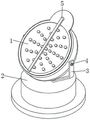
FIG. 1 is a schematic view of the overall structure of the present invention;
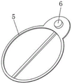
FIG. 2 is a partial schematic view of the present invention;
FIG. 3 is a schematic view of the drive mechanism of the present invention;
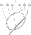
FIG. 4 is a schematic view of a wiping mechanism of the present invention.
In the figure: 1. an illumination lamp body; 2. a lamp body base; 3. a lamp body support; 4. adjusting screws; 5. a wiping mechanism; 501. wiping sponge; 502. positioning the snap ring; 503. wiping the bracket; 504. connecting holes; 505. installing a notch; 506. positioning a base; 6. a drive mechanism; 601. a mechanism housing; 602. a first gear; 603. a drive motor; 604. a drive shaft; 605. a second gear.
Detailed Description
In order to make the technical means, the creation characteristics, the achievement purposes and the effects of the utility model easy to understand, the utility model is further described with the specific embodiments.
As shown in fig. 1-4, an LED projection lamp capable of adjusting an irradiation angle includes a lamp body base 2, a lamp body support 3 is fixedly mounted on the upper surface of the lamp body base 2, an illumination lamp body 1 is movably mounted in the lamp body support 3, adjusting screws 4 are arranged on two sides of the lamp body support 3, a wiping mechanism 5 is fixedly mounted on the surface of the illumination lamp body 1, the wiping mechanism 5 includes a wiping sponge 501, a positioning snap ring 502, a wiping support 503, a connecting hole 504, a mounting opening 505 and a positioning base 506, a driving mechanism 6 is fixedly mounted on the back surface of the positioning base 506, the driving mechanism 6 includes a mechanism housing 601, a first gear 602, a driving motor 603, a driving shaft 604 and a second gear 605, and the illumination lamp body 1 is mounted on the lamp body base 2 through the lamp body support 3.
In order to clean dust on the lighting lamp body 1 conveniently, a lamp body support 3 is fixedly arranged on the upper surface of a lamp body base 2, the lighting lamp body 1 is movably arranged in the lamp body support 3, adjusting screws 4 are arranged on two sides of the lamp body support 3, a wiping mechanism 5 is fixedly arranged on the surface of the lighting lamp body 1, the wiping mechanism 5 comprises a wiping sponge 501, a positioning snap ring 502, a wiping support 503, a connecting hole 504, an installation notch 505 and a positioning base 506, a driving mechanism 6 is fixedly arranged on the back surface of the positioning base 506, the driving mechanism 6 comprises a mechanism shell 601, a first gear 602, a driving motor 603, a driving shaft 604 and a second gear 605, the positioning snap ring 502 is fixedly arranged on the surface of the lighting lamp body 1, the positioning base 506 is fixedly arranged on the positioning snap ring 502, the installation notch 505 is arranged on the surface of the positioning snap ring 506, the wiping support 503 is arranged above the positioning snap ring 502, and the wiping sponge 501 is fixedly arranged on the wiping support 503, a connecting hole 504 is arranged at one end edge of the wiping bracket 503, a thread is arranged on the inner side of the positioning snap ring 502, the positioning snap ring 502 is fixed on the illuminating lamp body 1 through the thread, the wiping sponge 501 is fixed on the wiping bracket 503 through glue, the wiping bracket 503 is arranged above the positioning snap ring 502 through a driving mechanism 6, the mechanism housing 601 is fixedly arranged on the back of the positioning base 506, a driving shaft 604 is movably arranged in the mechanism housing 601, a second gear 605 is fixedly arranged on the driving shaft 604, a driving motor 603 is fixedly arranged in the mechanism housing 601, a first gear 602 is fixedly arranged at the output end of the driving motor 603, the first gear 602 is meshed with the second gear 605 together, a bearing is arranged at the bottom of the mechanism housing 601, the driving shaft 604 is movably arranged in the mechanism housing 601 through the bearing, the driving shaft 604 penetrates through the positioning base 506 through an installation notch 505, the end of the driving shaft 604 is connected on the wiping bracket 503 through the connecting hole 504, mechanism shell 601 passes through the screw height on location base 506, can start driving motor 603 after the lamp body surface area accumulates the dust, and first gear 602 can drive second gear 605 rotatory after starting driving motor 603, and second gear 605 can drive shaft 604 rotatory after rotatory, and it will be at illumination lamp body 1 surface removal to wipe sponge 501 after drive shaft 604 is rotatory to clean up the dust on lamp body surface fast, prevent that light from darkening.
It should be noted that, when in actual use, the whole device is firstly installed at a use position, once dust is accumulated on the lighting lamp body 1, the driving motor 603 can be started, because the first gear 602 and the second gear 605 are meshed together, the bottom of the mechanism housing 601 is provided with a bearing, the driving shaft 604 is movably installed in the mechanism housing 601 through the bearing, and the tail end of the driving shaft 604 is connected to the wiping bracket 503 through the connecting hole 504, so that the first gear 602 can drive the second gear 605 to rotate after the driving motor 603 is started, the wiping sponge 501 at the tail end of the driving shaft 604 can be driven to rotate after the second gear 605 rotates, and the wiping sponge 501 is attached to the surface of the lighting lamp body 1 to move in the rotating process, so that dust on the surface of the lamp body can be cleaned quickly, and light rays can be prevented from becoming dark.
Finally, it should be noted that: although the present invention has been described in detail with reference to the foregoing embodiments, it will be apparent to those skilled in the art that changes may be made in the embodiments and/or equivalents thereof without departing from the spirit and scope of the utility model. Any modification, equivalent replacement, or improvement made within the spirit and principle of the present invention should be included in the protection scope of the present invention.
Claims (6)
1. The utility model provides an adjustable LED projecting lamp who shines angle which characterized in that: including lamp body base (2), fixed surface installs lamp body support (3) on lamp body base (2), movable mounting has illumination lamp body (1) in lamp body support (3), lamp body support (3) both sides are equipped with adjusting screw (4), illumination lamp body (1) fixed surface installs and cleans mechanism (5), clean mechanism (5) including cleaning sponge (501), location snap ring (502), clean support (503), connecting hole (504), installation opening (505) and location base (506), location base (506) back fixed mounting has actuating mechanism (6), actuating mechanism (6) are including mechanism shell (601), first gear (602), driving motor (603), drive shaft (604) and second gear (605).
2. The LED floodlight capable of adjusting the irradiation angle according to claim 1, wherein: location snap ring (502) fixed mounting is on illumination lamp body (1) surface, fixed mounting has location base (506) on location snap ring (502), installation opening (505) have been seted up on location base (506) surface, location snap ring (502) top is equipped with cleans support (503), clean support (503) and go up fixed mounting and clean sponge (501), clean support (503) one end edge and seted up connecting hole (504).
3. The LED floodlight capable of adjusting the irradiation angle according to claim 2, wherein: the lamp is characterized in that threads are arranged on the inner side of the positioning clamping ring (502), the positioning clamping ring (502) is fixed on the lighting lamp body (1) through the threads, the wiping sponge (501) is fixed on the wiping support (503) through glue, and the wiping support (503) is installed above the positioning clamping ring (502) through a driving mechanism (6).
4. The LED projection lamp with adjustable illumination angle of claim 3, wherein: the mechanism comprises a mechanism shell (601), a driving shaft (604) is movably mounted in the mechanism shell (601), a second gear (605) is fixedly mounted on the driving shaft (604), a driving motor (603) is fixedly mounted in the mechanism shell (601), and a first gear (602) is fixedly mounted at the tail end of the output of the driving motor (603).
5. The LED floodlight capable of adjusting the irradiation angle according to claim 4, wherein: the mechanism comprises a mechanism shell (601), a first gear (602), a second gear (605), a bearing, a driving shaft (604), a positioning base (506), a connecting hole (504), a connecting hole (506), a positioning base (506), a driving shaft (604) and a second gear (605), wherein the first gear (602) and the second gear (605) are meshed together, the bearing is arranged at the bottom of the mechanism shell (601), the driving shaft (604) is movably installed in the mechanism shell (601) through the bearing, the driving shaft (604) penetrates through the positioning base (506) through the installation notch (505), the tail end of the driving shaft (604) is connected to the wiping support (503), and the mechanism shell (601) is arranged on the positioning base (506) through the height of a screw.
6. The LED floodlight capable of adjusting the irradiation angle according to claim 5, wherein: the lighting lamp body (1) is arranged on the lamp body base (2) through the lamp body bracket (3).
Priority Applications (1)
| Application Number | Priority Date | Filing Date | Title |
|---|---|---|---|
| CN202123365059.5U CN216383841U (en) | 2021-12-29 | 2021-12-29 | LED projecting lamp of adjustable angle of illumination |
Applications Claiming Priority (1)
| Application Number | Priority Date | Filing Date | Title |
|---|---|---|---|
| CN202123365059.5U CN216383841U (en) | 2021-12-29 | 2021-12-29 | LED projecting lamp of adjustable angle of illumination |
Publications (1)
| Publication Number | Publication Date |
|---|---|
| CN216383841U true CN216383841U (en) | 2022-04-26 |
Family
ID=81238090
Family Applications (1)
| Application Number | Title | Priority Date | Filing Date |
|---|---|---|---|
| CN202123365059.5U Active CN216383841U (en) | 2021-12-29 | 2021-12-29 | LED projecting lamp of adjustable angle of illumination |
Country Status (1)
| Country | Link |
|---|---|
| CN (1) | CN216383841U (en) |
Cited By (2)
| Publication number | Priority date | Publication date | Assignee | Title |
|---|---|---|---|---|
| CN114811531A (en) * | 2022-04-28 | 2022-07-29 | 富盛光电(吴江)有限公司 | Backlight module and method for reducing thickness of backlight module |
| CN116734229A (en) * | 2023-08-14 | 2023-09-12 | 深圳市中科诺捷科技有限公司 | Plant lighting lamp for greenhouse |
-
2021
- 2021-12-29 CN CN202123365059.5U patent/CN216383841U/en active Active
Cited By (4)
| Publication number | Priority date | Publication date | Assignee | Title |
|---|---|---|---|---|
| CN114811531A (en) * | 2022-04-28 | 2022-07-29 | 富盛光电(吴江)有限公司 | Backlight module and method for reducing thickness of backlight module |
| CN114811531B (en) * | 2022-04-28 | 2024-03-22 | 富盛光电(吴江)有限公司 | Backlight module and method for reducing thickness of backlight module |
| CN116734229A (en) * | 2023-08-14 | 2023-09-12 | 深圳市中科诺捷科技有限公司 | Plant lighting lamp for greenhouse |
| CN116734229B (en) * | 2023-08-14 | 2023-10-13 | 深圳市中科诺捷科技有限公司 | Plant lighting lamp for greenhouse |
Similar Documents
| Publication | Publication Date | Title |
|---|---|---|
| CN216383841U (en) | LED projecting lamp of adjustable angle of illumination | |
| CN112032607A (en) | LED driving device and LED lighting device | |
| CN218001264U (en) | Install projecting lamp of radiating groove | |
| CN210860962U (en) | Automobile lamp bracket with automatic protection function for automobile lamp | |
| CN211821889U (en) | LED projecting lamp convenient to adjust illumination zone | |
| CN217109274U (en) | LED projecting lamp that surface has protector | |
| CN219867804U (en) | Street lamp with cleaning function | |
| CN216868296U (en) | LED projection lamp | |
| CN213040409U (en) | LED projecting lamp of many illuminating effect | |
| CN212644467U (en) | Street lamp for rural road illumination | |
| CN220489023U (en) | Light projector convenient to install | |
| CN221592655U (en) | Environment-friendly device for reducing light pollution | |
| CN218993302U (en) | Stage spotlight convenient to adjust | |
| CN218936259U (en) | Make things convenient for projecting lamp of angle modulation | |
| CN212252253U (en) | LED projecting lamp with high heat dissipating | |
| CN213118758U (en) | Track spotlight convenient to adjust | |
| CN218001278U (en) | Shine angle regulation structure and lamps and lanterns | |
| CN212273843U (en) | Self-cleaning road lighting high-pole lamp | |
| CN220038272U (en) | Outdoor building lighting projector | |
| CN215674939U (en) | LED moon lamp | |
| CN221780627U (en) | Light projector | |
| CN221825212U (en) | Anti-dizzy wall-washing projection lamp | |
| CN213930524U (en) | Lamp for adjusting light direction by using optical glass rod | |
| CN217952176U (en) | Novel anti-dazzle lampshade | |
| CN214501027U (en) | Modular ceiling lamp capable of being spliced universally |
Legal Events
| Date | Code | Title | Description |
|---|---|---|---|
| GR01 | Patent grant | ||
| GR01 | Patent grant |