CN216370459U - Automatic cutting machine for aluminum alloy section bars - Google Patents
Automatic cutting machine for aluminum alloy section bars Download PDFInfo
- Publication number
- CN216370459U CN216370459U CN202122760870.7U CN202122760870U CN216370459U CN 216370459 U CN216370459 U CN 216370459U CN 202122760870 U CN202122760870 U CN 202122760870U CN 216370459 U CN216370459 U CN 216370459U
- Authority
- CN
- China
- Prior art keywords
- aluminum alloy
- cutting machine
- equipment base
- clamping assembly
- automatic
- Prior art date
- Legal status (The legal status is an assumption and is not a legal conclusion. Google has not performed a legal analysis and makes no representation as to the accuracy of the status listed.)
- Active
Links
Images


Landscapes
- Sawing (AREA)
Abstract
The utility model discloses an automatic cutting machine for aluminum alloy sectional bars, which aims to solve the technical problems that full-automatic cutting cannot be realized, the cutting efficiency is poor, and more potential safety hazards exist in manual operation in the prior art. The automatic cutting machine for the aluminum alloy section bars comprises an equipment base and a side base fixedly arranged on the outer side of the equipment base; the upper end of the equipment base is provided with a screw rod assembly, the upper end of the screw rod assembly is provided with a movable clamping assembly, the movable clamping assembly is connected with the equipment base in a sliding mode, and the upper end of the equipment base is fixedly provided with a fixed clamping assembly. This aluminum alloy section bar automatic cutout machine only needs press from both sides tightly the section bar through activity centre gripping subassembly, drives aluminum alloy section bar through the lead screw subassembly and removes to suitable position, fixes the aluminum alloy section bar other end through fixed centre gripping subassembly to the full automatic cutout of aluminum alloy section bar is handled has been realized.
Description
Technical Field
The utility model belongs to the field of cutting tools, and particularly relates to an automatic cutting machine for aluminum alloy section bars.
Background
Nowadays, the cutting machine has extensive application in the material cutting field, and the aluminium alloy ex-trusions is wide range of usage after the cutting of various sizes, often can use the cutting machine to the cutting of aluminium alloy ex-trusions strip, through the processing of cutting machine to aluminium alloy ex-trusions strip, carries out multiple form to aluminium alloy ex-trusions strip and cuts.
At present, the cutting technology of the existing aluminum alloy section bars is mostly still cut through a manual operation machine, the manual operation machine is used for cutting, the cutting efficiency is poor, the manual operation has more potential safety hazards, and the use efficiency is poor.
Therefore, in order to solve the problem that the conventional automatic cutting machine for aluminum alloy section bars cannot perform full-automatic cutting after being used, the practicability of the automatic cutting machine for aluminum alloy section bars needs to be improved.
SUMMERY OF THE UTILITY MODEL
(1) Technical problem to be solved
Aiming at the defects of the prior art, the utility model aims to provide an automatic cutting machine for aluminum alloy sectional bars, and aims to solve the technical problems that full-automatic cutting cannot be realized, the cutting efficiency is poor, and more potential safety hazards exist in manual operation in the prior art.
(2) Technical scheme
In order to solve the technical problem, the utility model provides an automatic cutting machine for aluminum alloy section bars, which comprises an equipment base and a side seat fixedly arranged on the outer side of the equipment base; the upper end of equipment base is provided with the lead screw subassembly, the upper end of lead screw subassembly is provided with movable centre gripping subassembly, movable centre gripping subassembly with equipment base sliding connection, the upper end fixed mounting of equipment base has fixed centre gripping subassembly, the upper end of side seat is provided with cutting assembly, the inboard of equipment base is provided with the guide fill, the guide fill be located the below of activity centre gripping subassembly, the inboard reservation of side seat has the storehouse of collection.
When the automatic cutting machine for the aluminum alloy section bars is used, the aluminum alloy section bars are arranged in the movable clamping assembly and the fixed clamping assembly, the section bars are clamped tightly through the movable clamping assembly, the aluminum alloy section bars are driven to move to a proper position through the screw rod assembly, the other end of the aluminum alloy section bars is fixed through the fixed clamping assembly, the aluminum alloy section bars are cut through the cutting assembly, and therefore full-automatic cutting processing of the aluminum alloy section bars is achieved.
Preferably, the inside of lead screw subassembly is including the motor, the motor set up in the outside of equipment base, the output shaft of motor is provided with the threaded rod, the threaded rod with equipment base rotates to be connected, through the setting of motor, drives the rotation and handles the threaded rod, is connected through the rotation of threaded rod and equipment base, rotates spacing processing to the threaded rod.
Furthermore, the inside of lead screw subassembly is including the thread bush, the thread bush is established in the outside of threaded rod, the thread bush with the threaded rod lead screw is connected, is connected through the lead screw of threaded rod and thread bush and drives the slider and remove.
Still further, the inside of activity centre gripping subassembly is including the slider, slider fixed mounting be in the outside of thread bush, the slider with equipment base sliding connection, the upper end fixed mounting of slider has the fixed plate, and the slider drives the fixed plate and removes, and the fixed plate drives aluminum alloy section bar and removes to suitable position.
Still further, the inside of activity centre gripping subassembly is including vertical cylinder push pedal, vertical cylinder push pedal set up in the outside of fixed plate, the outside of fixed plate is provided with the side cylinder push pedal, fixed centre gripping subassembly structure with activity centre gripping subassembly structure is the same, presss from both sides tightly from top to bottom through starting vertical cylinder push pedal to the section bar, presss from both sides tightly about going on the section bar through starting the side cylinder push pedal.
Preferably, the inside of cutting subassembly is including the slide rail, the slide rail set up in the upper end of side seat, the outside of slide rail is provided with the saw bench, the slide rail with saw bench sliding connection, the outside of saw bench is provided with the saw bit, removes to cutting department along the slide rail through the saw bench, carries out cutting process to the aluminium alloy ex-trusions strip through the saw bit.
Furthermore, a support is fixedly mounted at the upper end of the side seat, a limiting groove is formed in the inner side of the support, the position of the limiting groove corresponds to that of the saw blade, the saw blade is limited through the limiting groove, and the position of the limiting groove is fixed through the support.
(3) Advantageous effects
Compared with the prior art, the utility model has the beneficial effects that: according to the automatic cutting machine for the aluminum alloy section bars, the aluminum alloy section bars are arranged at the movable clamping assembly and the fixed clamping assembly, the vertical air cylinder push plate is started to clamp the section bars up and down, the side air cylinder push plate is started to clamp the section bars left and right, the starting motor drives the threaded rod to rotate, the threaded rod is connected with the lead screw of the threaded sleeve to drive the sliding block to move, the sliding block drives the fixed plate to move, the fixed plate drives the aluminum alloy section bars to move to a proper position, the other end of the aluminum alloy section bars is fixed through the fixed clamping assembly, the aluminum alloy section bars are moved to a cutting position along the sliding rail through the saw table, and the saw blade is used for cutting the aluminum alloy section bars, so that the full-automatic cutting treatment for the aluminum alloy section bars is realized.
Drawings
In order to more clearly illustrate the embodiments of the present invention or the technical solutions in the prior art, the drawings used in the embodiments or the technical solutions in the prior art will be briefly described below, it is obvious that the drawings in the following description are only one embodiment of the present invention, and other drawings can be obtained by those skilled in the art without creative efforts.
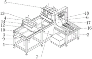
FIG. 1 is a schematic perspective view of an embodiment of the present invention;
FIG. 2 is a schematic cross-sectional perspective view of an embodiment of the present invention;
fig. 3 is a schematic structural diagram of a cross-sectional perspective view of an embodiment of the present invention.
The labels in the figures are: 1. an equipment base; 2. a side seat; 3. a screw assembly; 4. a movable clamping assembly; 5. fixing the clamping assembly; 6. a cutting assembly; 7. a material guide hopper; 8. a material collecting bin; 9. a motor; 10. a threaded rod; 11. a threaded sleeve; 12. a slider; 13. a fixing plate; 14. a vertical cylinder push plate; 15. a side cylinder push plate; 16. a slide rail; 17. a saw table; 18. a saw blade; 19. a support; 20. a limiting groove.
Detailed Description
In order to make the technical means, the original characteristics, the achieved purposes and the effects of the utility model easily understood and obvious, the technical solutions in the embodiments of the present invention are clearly and completely described below to further illustrate the utility model, and obviously, the described embodiments are only a part of the embodiments of the present invention, but not all the embodiments.
Example 1
The specific embodiment is used for an aluminum alloy profile strip automatic cutting machine, the schematic perspective structure of which is shown in fig. 1, and the schematic sectional perspective structure of which is shown in fig. 2, the aluminum alloy profile strip automatic cutting machine comprises an equipment base 1 and a side base 2 fixedly installed on the outer side of the equipment base 1; the upper end of equipment base 1 is provided with lead screw subassembly 3, the upper end of lead screw subassembly 3 is provided with activity centre gripping subassembly 4, activity centre gripping subassembly 4 and equipment base 1 sliding connection, the upper end fixed mounting of equipment base 1 has fixed centre gripping subassembly 5, the upper end of side seat 2 is provided with cutting assembly 6, the inboard of equipment base 1 is provided with guide fill 7, the below that is located activity centre gripping subassembly 4 of guide fill 7, the inboard reservation of side seat 2 has a feed bin 8 that gathers materials.
For the present embodiment, the shape and structure of the apparatus base 1 are set according to practical application, for example, the apparatus base 1 may have a rectangular structure, a circular structure, a polygonal structure, and the like.
Wherein, the inside of lead screw subassembly 3 is including motor 9, motor 9 sets up in the outside of equipment base 1, the output shaft of motor 9 is provided with threaded rod 10, threaded rod 10 rotates with equipment base 1 to be connected, setting through motor 9, drive rotation processing is carried out to threaded rod 10, be connected with equipment base 1's rotation through threaded rod 10, rotate limit processing to threaded rod 10, the inside of lead screw subassembly 3 is including thread bush 11, thread bush 11 sets up in the outside of threaded rod 10, thread bush 11 is connected with threaded rod 10 lead screw, it moves to drive slider 12 to be connected through threaded rod 10 and thread bush 11's lead screw.
This embodiment is used for aluminum alloy ex-trusions strip automatic cutout machine, its section three-dimensional structure sketch map is shown in fig. 3, the inside of activity centre gripping subassembly 4 is including slider 12, slider 12 fixed mounting is in the outside of thread bush 11, slider 12 and equipment base 1 sliding connection, the upper end fixed mounting of slider 12 has fixed plate 13, slider 12 drives fixed plate 13 and removes, fixed plate 13 drives aluminum alloy ex-trusions strip and removes to suitable position, the inside of activity centre gripping subassembly 4 is including vertical cylinder push pedal 14, vertical cylinder push pedal 14 sets up in the outside of fixed plate 13, the outside of fixed plate 13 is provided with side cylinder push pedal 15, fixed centre gripping subassembly 5 structure is the same with activity centre gripping subassembly 4 structure, press from both sides the section bar from top to bottom through starting vertical cylinder push pedal 14, press from both sides the section bar from both sides about through starting side cylinder push pedal 15.
Simultaneously, the inside of cutting assembly 6 is including slide rail 16, slide rail 16 sets up in the upper end of side seat 2, the outside of slide rail 16 is provided with saw bench 17, slide rail 16 and saw bench 17 sliding connection, the outside of saw bench 17 is provided with saw bit 18, remove to the cutting department along slide rail 16 through saw bench 17, cut the processing to the aluminium alloy ex-trusions strip through saw bit 18, the upper end fixed mounting of side seat 2 has support 19, spacing groove 20 has been seted up to support 19's inboard, spacing groove 20 position corresponds each other with the position of saw bit 18, setting through spacing groove 20, carry out limit to saw bit 18, carry out fixed processing through support 19 to the position of spacing groove 20.
When using this technical scheme's aluminum alloy ex-trusions strip automatic cutout machine, through arranging aluminum alloy ex-trusions strip in activity centre gripping subassembly 4 and the 5 departments of fixed centre gripping subassembly, press from both sides tightly the section bar from top to bottom through starting vertical cylinder push pedal 14, press from both sides tightly about going on the section bar through starting side cylinder push pedal 15, it rotates to drive threaded rod 10 through starter motor 9, it moves to drive slider 12 to be connected through the lead screw of threaded rod 10 with thread bush 11, slider 12 drives fixed plate 13 and removes, fixed plate 13 drives aluminum alloy ex-trusions strip and removes to suitable position, fix the aluminum alloy ex-trusions strip other end through fixed centre gripping subassembly 5, remove to cutting department along slide rail 16 through saw bench 17, cut the processing through saw bit 18 to aluminum alloy ex-trusions strip, thereby realized the full automatic cutout processing to aluminum alloy ex-trusions strip.
Having thus described the principal technical features and basic principles of the utility model, and the advantages associated therewith, it will be apparent to those skilled in the art that the utility model is not limited to the details of the foregoing illustrative embodiments, but is capable of other specific forms without departing from the spirit or essential characteristics thereof. The present embodiments are therefore to be considered in all respects as illustrative and not restrictive, the scope of the utility model being indicated by the appended claims rather than by the foregoing description, and all changes which come within the meaning and range of equivalency of the claims are therefore intended to be embraced therein.
Furthermore, it should be understood that although the present description is described in terms of various embodiments, not every embodiment includes only a single embodiment, and such descriptions are provided for clarity only, and those skilled in the art will recognize that the embodiments described herein can be combined as a whole to form other embodiments as would be understood by those skilled in the art.
Claims (7)
1. An automatic cutting machine for aluminum alloy sectional bars comprises an equipment base and a side seat fixedly installed on the outer side of the equipment base; the automatic feeding device is characterized in that a lead screw assembly is arranged at the upper end of the device base, a movable clamping assembly is arranged at the upper end of the lead screw assembly, the movable clamping assembly is connected with the device base in a sliding mode, a fixed clamping assembly is fixedly arranged at the upper end of the device base, a cutting assembly is arranged at the upper end of the side seat, a guide hopper is arranged on the inner side of the device base, the guide hopper is located below the movable clamping assembly, and a material collecting bin is reserved on the inner side of the side seat.
2. The automatic aluminum alloy profile bar cutting machine as claimed in claim 1, wherein a motor is arranged inside the screw rod assembly, the motor is arranged outside the equipment base, a threaded rod is arranged on an output shaft of the motor, and the threaded rod is rotatably connected with the equipment base.
3. The automatic cutting machine for aluminum alloy section bars as claimed in claim 2, wherein the screw rod assembly comprises a threaded sleeve inside, the threaded sleeve is arranged on the outer side of the threaded rod, and the threaded sleeve is connected with the threaded rod screw rod.
4. The automatic aluminum alloy profile bar cutting machine according to claim 3, wherein the movable clamping assembly comprises a sliding block inside, the sliding block is fixedly installed on the outer side of the threaded sleeve and is in sliding connection with the equipment base, and a fixing plate is fixedly installed at the upper end of the sliding block.
5. The automatic cutting machine for aluminum alloy section bars according to claim 4, characterized in that the movable clamping assembly comprises a vertical cylinder push plate inside, the vertical cylinder push plate is arranged on the outer side of the fixed plate, a side cylinder push plate is arranged on the outer side of the fixed plate, and the fixed clamping assembly is the same as the movable clamping assembly in structure.
6. The automatic cutting machine for aluminum alloy section bars according to claim 1, wherein the inside of the cutting assembly comprises a slide rail, the slide rail is arranged at the upper end of the side seat, a saw table is arranged outside the slide rail, the slide rail is connected with the saw table in a sliding manner, and a saw blade is arranged outside the saw table.
7. The automatic aluminum alloy profile bar cutting machine according to claim 6, wherein a support is fixedly mounted at the upper end of the side seat, a limiting groove is formed in the inner side of the support, and the position of the limiting groove corresponds to the position of the saw blade.
Priority Applications (1)
| Application Number | Priority Date | Filing Date | Title |
|---|---|---|---|
| CN202122760870.7U CN216370459U (en) | 2021-11-11 | 2021-11-11 | Automatic cutting machine for aluminum alloy section bars |
Applications Claiming Priority (1)
| Application Number | Priority Date | Filing Date | Title |
|---|---|---|---|
| CN202122760870.7U CN216370459U (en) | 2021-11-11 | 2021-11-11 | Automatic cutting machine for aluminum alloy section bars |
Publications (1)
| Publication Number | Publication Date |
|---|---|
| CN216370459U true CN216370459U (en) | 2022-04-26 |
Family
ID=81252517
Family Applications (1)
| Application Number | Title | Priority Date | Filing Date |
|---|---|---|---|
| CN202122760870.7U Active CN216370459U (en) | 2021-11-11 | 2021-11-11 | Automatic cutting machine for aluminum alloy section bars |
Country Status (1)
| Country | Link |
|---|---|
| CN (1) | CN216370459U (en) |
-
2021
- 2021-11-11 CN CN202122760870.7U patent/CN216370459U/en active Active
Similar Documents
| Publication | Publication Date | Title |
|---|---|---|
| CN110814429A (en) | Processing device based on bar processing disc sheet stock | |
| CN212976891U (en) | Cutting device of rear cover assembly | |
| CN216370459U (en) | Automatic cutting machine for aluminum alloy section bars | |
| CN210498624U (en) | Aluminum bar processing is with cuting device | |
| CN215146626U (en) | Full-automatic aluminum product processing all-in-one | |
| CN215146625U (en) | Multifunctional aluminum product processing machine | |
| CN214772229U (en) | Cutting device for packaging paper | |
| CN210615843U (en) | Sample clamping fixture mechanism of hydraulic broaching machine | |
| CN208895284U (en) | A kind of rapid cutting device of handware processing | |
| CN220533104U (en) | Metal cutting machine | |
| CN220740270U (en) | Cutting tool for forging processing | |
| CN218657012U (en) | Plate shearing machine | |
| CN217492895U (en) | Bottle lid side cut positioner | |
| CN221110138U (en) | Gear cutting machine for metal processing | |
| CN220920773U (en) | Copper wire shearing device | |
| CN217433188U (en) | Semi-automatic hot shearing machine for aluminum profiles | |
| CN218340721U (en) | Plate slotting bending machine | |
| CN219358746U (en) | Copper flexible connector processing fixing device | |
| CN216634594U (en) | Fixed-distance cutting machine for machining fiber casing | |
| CN221289187U (en) | Incision mould is used in sheet metal component processing | |
| CN221047436U (en) | Aluminum alloy cutting machine | |
| CN216096769U (en) | Slotting device for ratchet ring machining | |
| CN220944207U (en) | Grooving device for processing aluminum alloy rod piece | |
| CN217290683U (en) | Angle-adjustable aluminum alloy section machining and cutting device | |
| CN215468119U (en) | Motor rotor aluminum end ring shearing and recycling device |
Legal Events
| Date | Code | Title | Description |
|---|---|---|---|
| GR01 | Patent grant | ||
| GR01 | Patent grant |