CN216355457U - Electric power cabinet door and electric power cabinet - Google Patents
Electric power cabinet door and electric power cabinet Download PDFInfo
- Publication number
- CN216355457U CN216355457U CN202122916567.1U CN202122916567U CN216355457U CN 216355457 U CN216355457 U CN 216355457U CN 202122916567 U CN202122916567 U CN 202122916567U CN 216355457 U CN216355457 U CN 216355457U
- Authority
- CN
- China
- Prior art keywords
- cabinet
- door
- power cabinet
- cabinet door
- operation window
- Prior art date
- Legal status (The legal status is an assumption and is not a legal conclusion. Google has not performed a legal analysis and makes no representation as to the accuracy of the status listed.)
- Active
Links
Images


Abstract
The utility model relates to an electric cabinet door and an electric cabinet, which can perform local operation without opening a cabinet door switch. The technical scheme adopted comprises the following steps: the door body, the bottom of the door body is equipped with a set of interval arrangement's operation window, and corresponds the back of operation window is equipped with the installing frame, the front end of installing frame is equipped with the sliding closure baffle that can slide from top to bottom, and the rear end is equipped with the installing port corresponding with the operation window. The advantages are that: the bottom of the door body is provided with the operating window, so that emergency operation can be performed on some switches such as a breaker without opening the whole cabinet door.
Description
Technical Field
The utility model belongs to and relates to an electric power cabinet.
Background
The power distribution cabinet (box), the illumination distribution cabinet (box) and the metering cabinet (box) are power distribution system power distribution cabinet (box) and are final-stage equipment. The basic structure of the electric power cabinet comprises: the cabinet body and the cabinet door that articulates on the cabinet body, at various electrical equipment of the internal installation of cabinet, like control switch, circuit breaker, strapping table etc.. The tradition will be operated electrical equipment in the cabinet, generally need be with whole cabinet door switch, and the operation is comparatively troublesome, and has certain safety to imply.
SUMMERY OF THE UTILITY MODEL
The utility model aims to provide an electric power cabinet door and an electric power cabinet, which can perform local operation without opening a cabinet door switch.
In order to solve the above problems, the technical scheme adopted by the utility model comprises: the door body, its characterized in that: the door body is characterized in that a group of operation windows which are arranged at intervals are arranged at the bottom of the door body, an installation frame is arranged on the back face corresponding to the operation windows, a sliding cover baffle plate capable of sliding up and down is arranged at the front end of the installation frame, and an installation opening corresponding to the operation windows is arranged at the rear end of the installation frame.
Electric power cabinet door, its characterized in that: and the sliding cover baffle is provided with a handle extending out of the operation window.
Electric power cabinet door, its characterized in that: and a corresponding safety hole is arranged between the handle and the operation window.
Electric power cabinet door, its characterized in that: the safety hole is used for lead sealing or a padlock.
Electric power cabinet door, its characterized in that: the back of the door body corresponding to the operation window is provided with a sliding groove, and the sliding cover baffle is slidably arranged in the sliding groove.
Electric power cabinet door, its characterized in that: and a sealing gasket is arranged between the mounting frame and the door body.
The utility model provides an electric power cabinet, includes the cabinet body, its characterized in that: the cabinet body is hinged with the electric cabinet door.
The electric power cabinet, its characterized in that: and a mounting guide rail is arranged in the cabinet body and in front of the mounting opening corresponding to the mounting frame.
The electric power cabinet, its characterized in that: the bottom of the cabinet body is provided with a group of wire outlet holes which are arranged at intervals and correspond to the lower part of the installation guide rail.
The electric power cabinet, its characterized in that: a partition board is arranged in the cabinet body and corresponds to the upper portion of the mounting frame.
The electric cabinet door and the electric cabinet have the advantages that: the bottom of the door body is provided with the operating window, so that emergency operation can be performed on some switches such as a breaker without opening the whole cabinet door.
The present invention will be described in further detail with reference to the accompanying drawings.
Drawings
FIG. 1 is a schematic structural diagram of a power cabinet door according to the present invention, showing a front structure;
FIG. 2 is a schematic structural diagram of a power cabinet door of the present invention, showing a back structure;
FIG. 3 is an exploded view of the power cabinet door of the present invention;
FIG. 4 is a cross-sectional view of a power cabinet door of the present invention;
FIG. 5 is a schematic structural diagram of the mounting frame of the present invention;
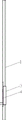
FIG. 6 is a schematic structural diagram of the electric cabinet of the present invention;
fig. 7 is a cross-sectional view of the electric cabinet of the present invention.
Detailed Description
Example 1:
referring to fig. 1-5, the electric cabinet door of the present invention includes a door body 1, a group of operation windows 2 arranged at intervals is arranged at the bottom of the door body 1, the number of the operation windows 2 is determined according to actual requirements, and when the electric cabinet door is used for a four-position electric meter box, four operation windows 2 are arranged and are respectively used for operating a circuit breaker in the electric meter box. And the back of the door body 1 corresponding to the operation window 2 is provided with an installation frame 3. The front end of the installation frame 3 is provided with a sliding cover baffle 4 capable of sliding up and down, the rear end of the installation frame 3 is provided with an installation opening 5 corresponding to the operation window 2, and the installation opening 5 can be used for installing an operation part of the circuit breaker.
Preferably, the sliding cover baffle 4 is provided with a handle 6 extending out of the operation window 2, and a user can hold the handle 6 to slide the sliding cover baffle 4 up and down. A corresponding safety hole 7 is arranged between the handle 6 and the operation window (2), and the safety hole 7 is used for lead sealing or padlock so as to improve the installation of the sliding cover baffle 4 and prevent the operation of unauthorized persons.
Preferably, a sliding groove 8 is formed in the back of the door body 1 corresponding to the operating window 2, and the sliding cover baffle 4 is slidably installed in the sliding groove 8, so that the sliding cover baffle 4 is installed.
Preferably, a sealing gasket 9 is arranged between the mounting frame 3 and the door body 1 to improve the dustproof and waterproof performance.
Example 2:
referring to fig. 6 to 7, the electric cabinet door of the present invention includes a cabinet body 10, and the cabinet body 10 is hinged with an electric cabinet door a according to embodiment 1. Preferably, an installation guide rail 11 is provided in the cabinet 10 in front of the installation opening 5 corresponding to the installation frame 3, and the guide rail type circuit breaker can be conveniently installed through the installation guide rail 11. A group of wire outlet holes 12 which are arranged at intervals are arranged at the bottom of the cabinet body 10 and below the mounting guide rail 11 to facilitate wire outlet. In the cabinet body 10, a partition plate 13 is arranged above the mounting frame 3, and the partition plate 13 isolates electric elements (mainly circuit breakers) in the operating window from other electric elements, so as to improve safety.
The foregoing is merely an embodiment of the present invention, and it should be noted that those skilled in the art can make various modifications and improvements without departing from the principle of the present invention, and such modifications and improvements should be considered as the protection scope of the present invention.
Claims (10)
1. The utility model provides an electric power cabinet door, includes door body (1), its characterized in that: the door body (1) bottom is equipped with a set of interval arrangement's operation window (2), and corresponds the back of operation window (2) is equipped with installing frame (3), the front end of installing frame (3) is equipped with slidable sliding closure baffle (4) from top to bottom, the rear end be equipped with operation window (2) corresponding installing port (5).
2. The power cabinet door of claim 1, wherein: and a handle (6) extending out of the operation window (2) is arranged on the sliding cover baffle (4).
3. The power cabinet door of claim 2, wherein: a corresponding safety hole (7) is arranged between the handle (6) and the operation window (2).
4. The power cabinet door of claim 3, wherein: the safety hole (7) is used for lead sealing or padlock.
5. The power cabinet door of claim 1, wherein: the back of the door body (1) corresponding to the operation window (2) is provided with a sliding groove (8), and the sliding cover baffle (4) is slidably arranged in the sliding groove (8).
6. The power cabinet door of claim 1, wherein: and a sealing gasket (9) is arranged between the mounting frame (3) and the door body (1).
7. An electric power cabinet, includes the cabinet body (10), its characterized in that: the cabinet body (10) is hinged with the electric cabinet door (a) of any one of claims 1-6.
8. The electrical cabinet of claim 7, wherein: and a mounting guide rail (11) is arranged in the cabinet body (10) and corresponds to the front of the mounting opening (5) of the mounting frame (3).
9. The electrical cabinet of claim 8, wherein: a group of wire outlet holes (12) which are arranged at intervals are arranged at the bottom of the cabinet body (10) and are arranged below the mounting guide rail (11).
10. The electrical cabinet of claim 7, wherein: a partition plate (13) is arranged in the cabinet body (10) and corresponds to the upper part of the mounting frame (3).
Priority Applications (1)
| Application Number | Priority Date | Filing Date | Title |
|---|---|---|---|
| CN202122916567.1U CN216355457U (en) | 2021-11-25 | 2021-11-25 | Electric power cabinet door and electric power cabinet |
Applications Claiming Priority (1)
| Application Number | Priority Date | Filing Date | Title |
|---|---|---|---|
| CN202122916567.1U CN216355457U (en) | 2021-11-25 | 2021-11-25 | Electric power cabinet door and electric power cabinet |
Publications (1)
| Publication Number | Publication Date |
|---|---|
| CN216355457U true CN216355457U (en) | 2022-04-19 |
Family
ID=81153758
Family Applications (1)
| Application Number | Title | Priority Date | Filing Date |
|---|---|---|---|
| CN202122916567.1U Active CN216355457U (en) | 2021-11-25 | 2021-11-25 | Electric power cabinet door and electric power cabinet |
Country Status (1)
| Country | Link |
|---|---|
| CN (1) | CN216355457U (en) |
-
2021
- 2021-11-25 CN CN202122916567.1U patent/CN216355457U/en active Active
Similar Documents
| Publication | Publication Date | Title |
|---|---|---|
| CN216355457U (en) | Electric power cabinet door and electric power cabinet | |
| CN207884110U (en) | A kind of power distribution cabinet | |
| CN206364433U (en) | Fixed AC metal closed high-tension switch cabinet | |
| CN2862046Y (en) | Metal-shielding mobile electric quantity management measuring cabinet | |
| CN201340975Y (en) | Sliding door type electric cabinet | |
| CN210123840U (en) | Safe type high tension switchgear | |
| CN216016105U (en) | Switch cabinet with optimized internal wiring space | |
| CN201252349Y (en) | Novel protective electric control cabinet | |
| CN214957901U (en) | Novel surface-mounted distribution box | |
| CN212366628U (en) | Metal armored high-voltage switch cabinet | |
| CN217036433U (en) | Cubical switchboard safety protection mechanism | |
| CN219123671U (en) | Three-phase metal casing electric energy metering box | |
| CN213460686U (en) | Distribution box with L-shaped movable slide rail type mounting plate | |
| CN219371727U (en) | Intelligent low-voltage switch cabinet | |
| CN216489180U (en) | Control cabinet with openable cabinet top | |
| CN218182751U (en) | Handle control type low-voltage switchgear based on thing networking | |
| CN218482551U (en) | Front-open type low-voltage incoming line switch cabinet | |
| CN211046052U (en) | Dust-protection type switch board | |
| CN212626706U (en) | Block terminal is used in security protection control | |
| CN220401205U (en) | Multifunctional metering box | |
| CN217589916U (en) | Turnover low-voltage switch cabinet body | |
| CN212114355U (en) | Explosion-proof mechanism of switch cabinet lighting lamp | |
| CN216720709U (en) | Heat dissipation air duct structure of electrical switch cabinet | |
| CN216355463U (en) | Industrial control cabinet convenient to install and detach | |
| CN213341404U (en) | Drawer type breaker outlet cabinet |
Legal Events
| Date | Code | Title | Description |
|---|---|---|---|
| GR01 | Patent grant | ||
| GR01 | Patent grant |