SUMMERY OF THE UTILITY MODEL
The utility model aims to provide a device for rapidly detecting the slope rate of a side slope, which enables the data during slope measurement to be more accurate, so that the slope rate measurement is more accurate, and the device has the advantages of simple structure, convenience in measurement and low manufacturing cost.
The embodiment of the utility model is realized by the following steps:
the embodiment of the application provides a rapid detection device for slope rate of a side slope, which comprises a side slope plate, a first measuring scale and a second measuring scale; one end of the first measuring scale is rotatably connected with one end of the slope plate, the other end of the first measuring scale is a free end, one end of the second measuring scale is rotatably connected with one end of the slope plate, the other end of the second measuring scale is a free end, and the first measuring scale and the second measuring scale are both provided with levelness measuring devices; first rectangular hole has been seted up along the measuring direction of above-mentioned first dipperstick in the above-mentioned first dipperstick, be equipped with first instruction line on the first rectangular hole between two relative short lateral walls, the extension line of above-mentioned first instruction line passes the hinge center of above-mentioned first dipperstick and above-mentioned side slope board, the second rectangular hole has been seted up along the measuring direction of above-mentioned second dipperstick in the above-mentioned second dipperstick, be equipped with the second instruction line on the second rectangular hole between two relative short lateral walls, the extension line of above-mentioned second instruction line passes the hinge center of above-mentioned second dipperstick and above-mentioned side slope board.
In some embodiments of the present invention, the first indication line is a red line, and the second indication line is a black line.
In some embodiments of the present invention, the first measuring scale and the second measuring scale are provided with circular grooves, and the levelness measuring device is provided in the circular grooves.
In some embodiments of the present invention, the levelness meter includes a shaft and a pointer, the pointer is rotatably connected to the shaft, and the shaft is disposed on a central axis of the circular groove.
In some embodiments of the present invention, the bottom of each of the two circular grooves is provided with a detection line, the detection line on the first measuring scale is perpendicular to the long side of the first measuring scale, and the detection line on the second measuring scale is parallel to the long side of the second measuring scale.
In some embodiments of the present invention, the slope plate is a retractable plate.
In some embodiments of the present invention, the slope plate is provided with a fixing device.
In some embodiments of the present invention, the fixing device includes a plurality of fixing pins, and the plurality of fixing pins are uniformly distributed on the slope plate.
In some embodiments of the present invention, the slope plate is provided with a first clamping plate and a second clamping plate, the first clamping plate is provided with a first clamping groove for clamping the first measuring scale, and the second clamping plate is provided with a second clamping groove for clamping the second measuring scale.
In some embodiments of the present invention, rubber pads are disposed on inner side walls of the first engaging groove and the second engaging groove.
Compared with the prior art, the embodiment of the utility model has at least the following advantages or beneficial effects:
a rapid detection device for slope rate of a side slope comprises a side slope plate, a first measuring scale and a second measuring scale; one end of the first measuring scale is rotatably connected with one end of the slope plate, the other end of the first measuring scale is a free end, one end of the second measuring scale is rotatably connected with one end of the slope plate, the other end of the second measuring scale is a free end, and the first measuring scale and the second measuring scale are both provided with levelness measuring devices; first rectangular hole has been seted up along the measuring direction of above-mentioned first dipperstick in the above-mentioned first dipperstick, be equipped with first instruction line on the first rectangular hole between two relative short lateral walls, the extension line of above-mentioned first instruction line passes the hinge center of above-mentioned first dipperstick and above-mentioned side slope board, the second rectangular hole has been seted up along the measuring direction of above-mentioned second dipperstick in the above-mentioned second dipperstick, be equipped with the second instruction line on the second rectangular hole between two relative short lateral walls, the extension line of above-mentioned second instruction line passes the hinge center of above-mentioned second dipperstick and above-mentioned side slope board.
The first measuring scale, the second measuring scale and the slope plate form a triangular structure for detecting the slope rate of the slope; at the during operation, place the side slope board on the side slope, then rotate first dipperstick and second dipperstick, levelness caliber through on first dipperstick and the second dipperstick is measured, first dipperstick rotates to the horizontal direction, the second dipperstick rotates to vertical direction, then read out the measured data on first dipperstick and the second dipperstick, can reach the slope rate of side slope through calculating, moreover, the steam generator is simple in structure, and convenient for operation, and whole device simple structure, and convenient for carrying, low in manufacturing cost.
When the first measuring scale rotates to the horizontal direction and the second measuring scale rotates to the vertical direction, the first indicating line and the second indicating line intersect vertically and intersect at one point when viewed from the front, and the data on the first measuring scale indicated by the second indicating line and the data on the second measuring scale indicated by the first indicating line are read, so that the measured data are more accurate because the extension line of the first indicating line passes through the hinge center of the first measuring scale and the slope plate, the extension line of the second indicating line passes through the hinge center of the second measuring scale and the hinge center of the slope plate, the connecting line between the two hinge points is parallel to the slope surface, the two hinge points and the intersection point form a right triangle, and the distance from the hinge center of the first measuring scale and the hinge center of the slope plate to the intersection point (the intersection point of the first indicating line and the second indicating line) is the real data measured by the first measuring scale, the distance from the hinged center of the first measuring scale and the side slope plate to the intersection point (the intersection point of the first indicating line and the second indicating line) is the real data measured by the second measuring scale, the measured boundary slope rate is more accurate, and the construction effect is better.
Detailed Description
In order to make the objects, technical solutions and advantages of the embodiments of the present invention clearer, the technical solutions in the embodiments of the present invention will be clearly and completely described below with reference to the drawings in the embodiments of the present invention, and it is obvious that the described embodiments are some, but not all, embodiments of the present invention. The components of embodiments of the present invention generally described and illustrated in the figures herein may be arranged and designed in a wide variety of different configurations.
Thus, the following detailed description of the embodiments of the present invention, presented in the figures, is not intended to limit the scope of the utility model, as claimed, but is merely representative of selected embodiments of the utility model. All other embodiments, which can be derived by a person skilled in the art from the embodiments given herein without making any creative effort, shall fall within the protection scope of the present invention.
It should be noted that: like reference numbers and letters refer to like items in the following figures, and thus, once an item is defined in one figure, it need not be further defined and explained in subsequent figures.
In the description of the embodiments of the present invention, it should be noted that, if the terms "center", "upper", "lower", "left", "right", "vertical", "horizontal", "inner", "outer", etc. indicate an orientation or a positional relationship based on the orientation or the positional relationship shown in the drawings, or an orientation or a positional relationship which is usually placed when the products of the present invention are used, the description is only for convenience and simplicity, and the indication or the suggestion that the referred device or element must have a specific orientation, be constructed in a specific orientation, and be operated, and thus, the present invention should not be construed as being limited. Furthermore, the terms "first," "second," and the like are used merely to distinguish one description from another, and are not to be construed as indicating or implying relative importance.
Furthermore, the terms "horizontal", "vertical", "overhang" and the like do not require that the components be absolutely horizontal or overhang, but may be slightly inclined. For example, "horizontal" merely means that the direction is more horizontal than "vertical" and does not mean that the structure must be perfectly horizontal, but may be slightly inclined.
In the description of the embodiments of the present invention, it should be further noted that unless otherwise explicitly stated or limited, the terms "disposed," "mounted," "connected," and "connected" should be interpreted broadly, and may be, for example, fixedly connected, detachably connected, or integrally connected; can be mechanically or electrically connected; they may be connected directly or indirectly through intervening media, or they may be interconnected between two elements. The specific meanings of the above terms in the present invention can be understood by those skilled in the art according to specific situations.
Example 1
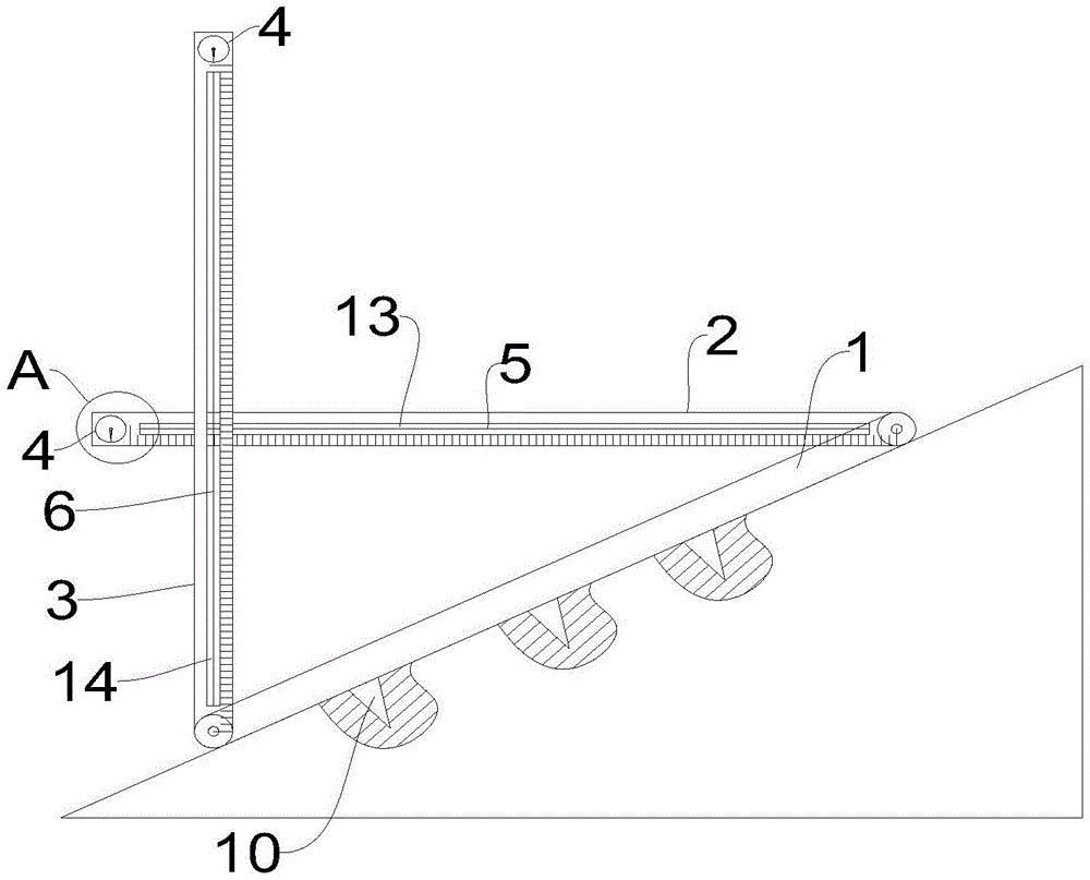
As shown in fig. 1-3, the present embodiment provides a device for rapidly detecting a slope ratio of a side slope, which includes a side slope plate 1, a first measuring ruler 2 and a second measuring ruler 3; one end of the first measuring scale 2 is rotatably connected with one end of the side slope plate 1, the other end is a free end, one end of the second measuring scale 3 is rotatably connected with one end of the side slope plate 1, the other end is a free end, and the first measuring scale 2 and the second measuring scale 3 are both provided with levelness measuring devices 4; first rectangular hole 13 has been seted up along the measuring direction of above-mentioned first dipperstick 2 in the above-mentioned first dipperstick 2, be equipped with first instruction line 5 on the first rectangular hole 13 between two relative short sidewalls, the extension line of above-mentioned first instruction line 5 passes the articulated center of above-mentioned first dipperstick 2 and above-mentioned side slope board 1, second rectangular hole 14 has been seted up along the measuring direction of above-mentioned second dipperstick 3 in the above-mentioned second dipperstick 3, be equipped with second instruction line 6 on the second rectangular hole 14 between two relative short sidewalls, the extension line of above-mentioned second instruction line 6 passes the articulated center of above-mentioned second dipperstick 3 and above-mentioned side slope board 1.
In the embodiment, the first measuring scale 2, the second measuring scale 3 and the slope plate 1 form a triangular structure for detecting the slope rate of the slope; at the during operation, place slope board 1 on the side slope, then rotate first dipperstick 2 and second dipperstick 3, levelness caliber 4 through on first dipperstick 2 and the second dipperstick 3 is measured, first dipperstick 2 rotates to the horizontal direction, second dipperstick 3 rotates to vertical direction, then read out the measured data on first dipperstick 2 and the second dipperstick 3, can reach the slope rate of side slope through calculating, moreover, the steam generator is simple in structure, and convenient for operation, and whole device convenient to carry, low in manufacturing cost.
When the first measuring scale 2 is rotated to the horizontal direction and the second measuring scale 3 is rotated to the vertical direction, the first indication line 5 and the second indication line 6 are vertically crossed and crossed at a point when viewed from the front, and the data on the first measuring scale 2 indicated by the second indication line 6 and the data on the second measuring scale 3 indicated by the first indication line 5 are read, and the measured data is more accurate because the extension line of the first indication line 5 passes through the hinge center of the first measuring scale 2 and the side slope plate 1, the extension line of the second indication line 6 passes through the hinge center of the second measuring scale 3 and the hinge center of the side slope plate 1, the connecting line between the two hinge points is parallel to the slope surface, and the two hinge points and the intersection point form a right triangle, and the distance from the hinge center of the first measuring scale 2 and the hinge center of the side slope plate 1 to the intersection point (the intersection point of the first indication line 5 and the second indication line 6) is the real data measured by the first measuring scale 2, the distance from the hinged center of the first measuring scale 2 and the slope plate 1 to the intersection point (the intersection point of the first indicating line 5 and the second indicating line 6) is the real data measured by the second measuring scale 3, the measured boundary slope rate is more accurate, and the construction effect is better; the first and second rectangular apertures 13, 14 are provided to make the reading at the intersection of the first and second indicator lines 5, 6 clearer, without the need to read through the dipstick itself, making the reading more accurate.
In some embodiments of the present invention, the first indication line 5 is a red line, and the second indication line 6 is a black line.
In the above embodiment, the first indicator line 5 is a red line, and the second indicator line 6 is a black line, so that the intersection of the first indicator line 5 and the second indicator line 6 is more obvious, and is easily recognized by a measurer, and then data is read.
Specifically, the color of the first indicator line 5 may be other colors, and the color of the second indicator line 6 may be other colors, as long as the colors of the first indicator line 5 and the second indicator line 6 are different, and the intersection point is clearly visible.
Example 2
As shown in fig. 1 to 3, in this embodiment, in addition to embodiment 1, circular grooves 7 are provided in both the first measuring scale 2 and the second measuring scale 3, and the levelness measuring instrument 4 is provided in the circular grooves 7.
In the present embodiment, the circular groove 7 is used to protect the levelness meter 4 so that the levelness meter 4 is protected from external damage, thereby preventing the entire apparatus from being damaged, which is convenient.
In some embodiments of the present invention, the levelness meter 4 includes a rotating shaft and a pointer 8, the pointer 8 is rotatably connected to the rotating shaft, and the rotating shaft is disposed at a central axis of the circular groove 7.
In the above-mentioned embodiment, pointer 8 can revolute the rotation of axes, and pointer 8 is perpendicular downwards all the time because gravity, and when pointer 8 on the first dipperstick 2 was perpendicular with the sideline of first dipperstick 2, first dipperstick 2 was in the horizontality, and when pointer 8 on the second dipperstick 3 was parallel with the sideline of second dipperstick 3, second dipperstick 3 was in vertical state to carry out the data reading of first dipperstick 2 and second dipperstick 3, it is more convenient.
In some embodiments of the present embodiment, a detection line 9 is provided at the bottom of each of the two circular grooves 7, the detection line 9 on the first measuring scale 2 is perpendicular to the long side of the first measuring scale 2, and the detection line 9 on the second measuring scale 3 is parallel to the long side of the second measuring scale 3.
In the above-mentioned embodiment, when pointer 8 on the first dipperstick 2 coincides with detection line 9 on it, think that first dipperstick 2 is in horizontal position promptly, when pointer 8 on the second dipperstick 3 coincides with detection line 9 on it, think that second dipperstick 3 is in vertical position promptly to first dipperstick 2 and second dipperstick 3 reachs the measuring position, and is more convenient, is more convenient for confirm the measuring position of first dipperstick 2 and second dipperstick 3, makes its position more accurate.
Example 3
As shown in fig. 1 to 3, in the present embodiment, on the basis of some of the above embodiments, the slope board 1 is a telescopic board.
In this embodiment, the side slope plate 1 is a telescopic plate, so that the length of the side slope plate 1 can be adjusted, the slope rate of the side slope can be measured for multiple times, and the measured data is more accurate.
In some embodiments of the present embodiment, the slope board 1 is provided with a fixing device.
In the above embodiment, the fixing device is used to fix the slope board 1 on the slope, so that the device does not need to be held by the user when measuring, and after fixing, the measured data is more accurate.
In some embodiments of the present invention, the fixing device includes a plurality of fixing pins 10, and the fixing pins 10 are uniformly distributed on the slope plate 1.
In some embodiments of the present embodiment, the plurality of fixing pins 10 are uniformly distributed on the slope sheet 1, so that the slope sheet 1 can be better fixed on the slope, and the processing cost is low.
Example 4
As shown in fig. 1 to 3, in this embodiment, on the basis of some of the above embodiments, the slope board 1 is provided with a first engaging plate 11 and a second engaging plate 12, the first engaging plate 11 is provided with a first engaging groove for engaging with the first measuring scale 2, and the second engaging plate 12 is provided with a second engaging groove for engaging with the second measuring scale 3.
In this embodiment, when the device did not use, can rotate first dipperstick 2 and second dipperstick 3 get into first joint inslot to first dipperstick 2 joint, get into second joint inslot to 3 joints of second dipperstick, thereby make the vertical space of whole device diminish, first dipperstick 2 and second dipperstick 3 are also fixed in addition, avoided first dipperstick 2 and second dipperstick 3 to rotate in disorder, increased the transport degree of difficulty of porter, it is more convenient.
In some embodiments of this embodiment, the first engaging groove and the second engaging groove are both provided with rubber pads.
In above-mentioned embodiment, the rubber pad makes first dipperstick 2 and second dipperstick 3 joint get into first joint groove and second joint inslot back respectively, avoids first dipperstick 2 and second dipperstick 3 when the joint, and there is the grinding mark on the surface, influences reading of data, has the existence of rubber pad moreover for first dipperstick 2 and second dipperstick 3's fixed more stable.
In summary, the embodiment of the present invention provides a device for rapidly detecting a slope ratio of a side slope, which includes a side slope plate 1, a first measuring ruler 2 and a second measuring ruler 3; one end of the first measuring scale 2 is rotatably connected with one end of the side slope plate 1, the other end is a free end, one end of the second measuring scale 3 is rotatably connected with one end of the side slope plate 1, the other end is a free end, and the first measuring scale 2 and the second measuring scale 3 are both provided with levelness measuring devices 4; first rectangular hole 13 has been seted up along the measuring direction of above-mentioned first dipperstick 2 in the above-mentioned first dipperstick 2, be equipped with first instruction line 5 on the first rectangular hole 13 between two relative short sidewalls, the extension line of above-mentioned first instruction line 5 passes the articulated center of above-mentioned first dipperstick 2 and above-mentioned side slope board 1, second rectangular hole 14 has been seted up along the measuring direction of above-mentioned second dipperstick 3 in the above-mentioned second dipperstick 3, be equipped with second instruction line 6 on the second rectangular hole 14 between two relative short sidewalls, the extension line of above-mentioned second instruction line 6 passes the articulated center of above-mentioned second dipperstick 3 and above-mentioned side slope board 1.
In the embodiment, the first measuring scale 2, the second measuring scale 3 and the slope plate 1 form a triangular structure for detecting the slope rate of the slope; at the during operation, place slope board 1 on the side slope, then rotate first dipperstick 2 and second dipperstick 3, levelness caliber 4 through on first dipperstick 2 and the second dipperstick 3 is measured, first dipperstick 2 rotates to the horizontal direction, second dipperstick 3 rotates to vertical direction, then read out the measured data on first dipperstick 2 and the second dipperstick 3, can reach the slope rate of side slope through calculating, moreover, the steam generator is simple in structure, and convenient for operation, and whole device convenient to carry, low in manufacturing cost.
When the first measuring scale 2 is rotated to the horizontal direction and the second measuring scale 3 is rotated to the vertical direction, the first indication line 5 and the second indication line 6 are vertically crossed and crossed at a point when viewed from the front, and the data on the first measuring scale 2 indicated by the second indication line 6 and the data on the second measuring scale 3 indicated by the first indication line 5 are read, and the measured data is more accurate because the extension line of the first indication line 5 passes through the hinge center of the first measuring scale 2 and the side slope plate 1, the extension line of the second indication line 6 passes through the hinge center of the second measuring scale 3 and the hinge center of the side slope plate 1, the connecting line between the two hinge points is parallel to the slope surface, and the two hinge points and the intersection point form a right triangle, and the distance from the hinge center of the first measuring scale 2 and the hinge center of the side slope plate 1 to the intersection point (the intersection point of the first indication line 5 and the second indication line 6) is the real data measured by the first measuring scale 2, the distance from the hinged center of the first measuring scale 2 and the slope plate 1 to the intersection point (the intersection point of the first indicating line 5 and the second indicating line 6) is the real data measured by the second measuring scale 3, the measured boundary slope rate is more accurate, and the construction effect is better; the first and second rectangular apertures 13, 14 are provided to make the reading at the intersection of the first and second indicator lines 5, 6 clearer, without the need to read through the dipstick itself, making the reading more accurate.
The above is only a preferred embodiment of the present invention, and is not intended to limit the present invention, and various modifications and changes will occur to those skilled in the art. Any modification, equivalent replacement, or improvement made within the spirit and principle of the present invention should be included in the protection scope of the present invention.