CN216344504U - Prevent warm logical pipe connection device of building of leakage - Google Patents
Prevent warm logical pipe connection device of building of leakage Download PDFInfo
- Publication number
- CN216344504U CN216344504U CN202123053501.0U CN202123053501U CN216344504U CN 216344504 U CN216344504 U CN 216344504U CN 202123053501 U CN202123053501 U CN 202123053501U CN 216344504 U CN216344504 U CN 216344504U
- Authority
- CN
- China
- Prior art keywords
- connecting piece
- heating
- pipeline
- warm logical
- piece
- Prior art date
- Legal status (The legal status is an assumption and is not a legal conclusion. Google has not performed a legal analysis and makes no representation as to the accuracy of the status listed.)
- Active
Links
Images


Landscapes
- Joints Allowing Movement (AREA)
Abstract
The utility model relates to the technical field of heating and ventilation pipeline connection, in particular to a leakage-proof building heating and ventilation pipeline connecting device which comprises a first connecting piece, wherein a second connecting piece is arranged at the bottom end of the first connecting piece. The user can be with first connecting piece through rotating the bolt, second connecting piece and first warm logical pipeline are fixed, can make to support the piece to be inconsistent with the warm logical pipeline of second through first threaded rod, thereby warm logical pipeline and the first warm logical pipeline of laminating mutually with the second, thereby warm logical pipeline and the warm logical pipeline of second with first warm and be connected, can seal the junction of the warm logical pipeline of first warm logical pipeline and second through first sealed pad, can avoid the warm logical pipeline of first warm logical pipeline and second to take place to buckle through the stereotyped plate, this device sealing performance is better, avoid the warm logical pipeline junction of first warm logical pipeline and second to take place to leak, and connect simple and conveniently, practice thrift user installation time, user's work efficiency is improved.
Description
Technical Field
The utility model relates to the technical field of heating and ventilation pipeline connection, in particular to a leakage-proof building heating and ventilation pipeline connecting device.
Background
The application range of the heating and ventilation pipeline is very wide, the purifying system air return pipe, the central air conditioning ventilation pipe, the industrial air supply and exhaust ventilation pipe, the environmental protection system air suction and exhaust pipe, the mine gas drainage pipe, the mine rubberized cloth air duct and the like are variable according to the requirements, the thickness and the specification of the heating and ventilation pipeline are usually variable according to requirements, two ends of the air pipe are always externally connected with accessories in connection, generally, two ends of the heating and ventilation pipeline are not provided with grooves and are provided with sealing rings, and the heating and ventilation pipeline can be laid and connected together when a building is constructed;
at present current warm logical pipeline connecting device when connecting, sealing performance is relatively poor, and the user is also comparatively troublesome when using, the time-wasting, thereby long-time use back, can make the not hard up condition of emergence leakage of junction.
SUMMERY OF THE UTILITY MODEL
The utility model aims to solve the defects in the prior art and provides a leakage-proof connecting device for a building heating and ventilation pipeline.
In order to achieve the purpose, the utility model provides the following technical scheme: a leakage-proof building heating and ventilation pipeline connecting device comprises a first connecting piece, wherein a second connecting piece is arranged at the bottom end of the first connecting piece, first threaded holes are formed in four face angles at the top end of the first connecting piece and penetrate through the first connecting piece to extend into the second connecting piece, bolts are connected into the first threaded holes through threads, moving grooves are formed in the sides, close to each other, of the first connecting piece and the second connecting piece, a first heating and ventilation pipeline is arranged at one end between the first connecting piece and the second connecting piece, a second heating and ventilation pipeline is arranged at the other end between the first connecting piece and the second connecting piece, one end of the second heating and ventilation pipeline slides in the moving grooves, a first sealing gasket is fixedly connected to one end of the second heating and ventilation pipeline, and two groups of collecting grooves are formed in one end of the moving grooves, the improved structure of the anti-bending device is characterized in that the inside of the take-up groove is all slidably connected with the supporting block, the inner wall of one end of the take-up groove is provided with second threaded holes, the inside of each second threaded hole is connected with a first threaded rod through threads, one end of each first threaded rod is fixedly connected with a first rotating piece, the bottom ends of the first connecting pieces are fixedly connected with two groups of second sealing gaskets, and the two ends of each first connecting piece are provided with anti-bending mechanisms.
Preferably, it is a set of receive the groove and be located the inside of first connecting piece, another group receive the groove and be located the inside of second connecting piece, conveniently contradict the warm logical pipeline of second for the warm logical pipeline atress of second is even.
Preferably, one side of first sealed pad is laminated with first warm logical pipeline mutually, the bottom that the second sealed pad all laminates with the second connecting piece mutually, fills up through first warm logical pipeline and second and can improve the leakproofness between first warm logical pipeline and the warm logical pipeline of second and first connecting piece and the second connecting piece.
Preferably, prevent that crooked mechanism includes that spout, slider, shaped plate, third screw hole, second threaded rod and second change the piece, two sets of spouts have all been seted up at the both ends of first connecting piece and second connecting piece, all sliding connection has the slider in the inside of spout, the both ends of first connecting piece and second connecting piece all are provided with two sets of shaped plates, and the one side that the shaped plate is close to each other all laminates mutually with first warm logical pipeline and second warm logical pipeline, the one end of shaped plate all with slider fixed connection, two sets of third threaded holes have all been seted up to the one end of shaped plate, the inside of third threaded hole all has the second threaded rod through threaded connection, the one end of second threaded rod all fixedly connected with second changes the piece, can avoid the junction of first warm logical pipeline and the warm logical pipeline of second to take place the bending.
Preferably, the second threaded rod penetrates through the positioning plate, the size of the sliding groove is matched with that of the sliding block, and the matched size facilitates the movement of the sliding block.
Preferably, one end of the first threaded rod is connected with the abutting block through a bearing, the size of the accommodating groove is matched with that of the abutting block, and the matched size facilitates movement of the abutting block.
Preferably, the second screw hole all runs through first connecting piece and second connecting piece respectively, the equal fixedly connected with lug of surface of first commentaries on classics piece can increase the frictional force between user's hand and the first commentaries on classics piece through the lug, and convenience of customers rotates first commentaries on classics piece.
Preferably, one side that first connecting piece and second connecting piece are close to each other all laminates with first warm logical pipeline mutually, the external diameter of warm logical pipeline one end of second and the internal diameter looks adaptation of shifting chute, the removal of the warm logical pipeline of size convenience second of looks adaptation.
Compared with the prior art, the utility model has the beneficial effects that:
after a user places the first heating and ventilation pipeline and the second heating and ventilation pipeline inside the second connecting piece, the first connecting piece and the second connecting piece can be fixed through rotating the bolt, so that the first heating and ventilation pipeline is fixed, the user can enable the abutting block to abut against one end of the second heating and ventilation pipeline through the first threaded rod when rotating the first rotating piece, so that one end of the second heating and ventilation pipeline is attached to one end of the first heating and ventilation pipeline, so that the first heating and ventilation pipeline and the second heating and ventilation pipeline are connected, the joint of the first heating and ventilation pipeline and the second heating and ventilation pipeline can be sealed through the first sealing gasket, the first heating and ventilation pipeline and the second heating and ventilation pipeline can be prevented from being bent through the shaping plate, and the shaping plate can be connected through the second threaded rod and the second rotating piece, the device has good sealing performance, the joint of the first heating and ventilation pipeline and the second heating and ventilation pipeline is prevented from being leaked, and the connection is simple and convenient, the installation time of the user is saved, and the working efficiency of the user is improved.
Drawings
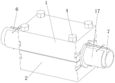
FIG. 1 is a perspective view of the present invention;
FIG. 2 is a schematic cross-sectional perspective view of the first connector, the second connector and the receiving slot of the present invention;
FIG. 3 is a schematic cross-sectional perspective view of a setting plate, a third threaded bore and a second threaded shaft of the present invention;
FIG. 4 is an exploded perspective view of the first connecting member, the second connecting member and the resisting block of the present invention;
fig. 5 is an exploded perspective view of a second connector, a setting plate and a second threaded rod of the present invention.
In the figure: 1. a first connecting member; 2. a second connecting member; 3. a first threaded hole; 4. a bolt; 5. a moving groove; 6. a first heating and ventilation pipeline; 7. a second heating and ventilation pipeline; 8. a first gasket; 9. collecting a groove; 10. a resisting block; 11. a second threaded hole; 12. a first threaded rod; 13. a first rotating member; 14. a second gasket; 15. a chute; 16. a slider; 17. a shape-setting plate; 18. a third threaded hole; 19. a second threaded rod; 20. and a second rotating member.
Detailed Description
The technical solutions in the embodiments of the present invention will be clearly and completely described below with reference to the drawings in the embodiments of the present invention, and it is obvious that the described embodiments are only a part of the embodiments of the present invention, and not all of the embodiments. All other embodiments, which can be derived by a person skilled in the art from the embodiments given herein without making any creative effort, shall fall within the protection scope of the present invention.
Referring to fig. 1-5, an embodiment of the present invention is shown:
a leakage-proof building heating and ventilation pipeline connecting device comprises a first connecting piece 1, wherein a second connecting piece 2 is arranged at the bottom end of the first connecting piece 1, first threaded holes 3 are formed in four corners of the top end of the first connecting piece 1, the first threaded holes 3 penetrate through the first connecting piece 1 and extend into the second connecting piece 2, bolts 4 are connected into the first threaded holes 3 through threads, moving grooves 5 are formed in one sides, close to each other, of the first connecting piece 1 and the second connecting piece 2, a first heating and ventilation pipeline 6 is arranged at one end between the first connecting piece 1 and the second connecting piece 2, a second heating and ventilation pipeline 7 is arranged at the other end between the first connecting piece 1 and the second connecting piece 2, one end of the second heating and ventilation pipeline 7 slides in the moving grooves 5, a first sealing gasket 8 is fixedly connected to one end of the second heating and ventilation pipeline 7, two groups of collecting grooves 9 are formed in one end of the moving grooves 5, the interior of the receiving groove 9 is connected with a resisting block 10 in a sliding mode, the inner wall of one end of the receiving groove 9 is provided with a second threaded hole 11, the interior of the second threaded hole 11 is connected with a first threaded rod 12 through threads, one end of the first threaded rod 12 is fixedly connected with a first rotating piece 13, the bottom end of the first connecting piece 1 is fixedly connected with two groups of second sealing gaskets 14, and two ends of the first connecting piece 1 are provided with anti-bending mechanisms;
further, the bending prevention mechanism comprises a sliding groove 15, a sliding block 16, a shaping plate 17, a third threaded hole 18, a second threaded rod 19 and a second rotating piece 20, two groups of sliding grooves 15 are formed in two ends of the first connecting piece 1 and the second connecting piece 2, the sliding block 16 is connected inside the sliding groove 15 in a sliding mode, two groups of shaping plates 17 are arranged at two ends of the first connecting piece 1 and the second connecting piece 2, one sides, close to each other, of the shaping plates 17 are attached to the first heating and ventilation pipeline 6 and the second heating and ventilation pipeline 7, one ends of the shaping plates 17 are fixedly connected with the sliding block 16, one ends of the shaping plates 17 are provided with two groups of third threaded holes 18, the inside of the third threaded holes 18 are connected with the second threaded rod 19 in a threaded mode, one ends of the second threaded rods 19 are fixedly connected with the second rotating piece 20, a user inserts the sliding block 16 at one end of the shaping plate 17 into the sliding groove 15 again, so that one side, close to each other, of the shaping plates 17 is attached to the first heating and ventilation pipeline 6 and the second heating and the second ventilation pipeline 7, at this time, the user inserts the second threaded rod 19 into the third threaded hole 18, the user rotates the second rotating member 20, the second rotating member 20 drives the second threaded rod 19 to rotate, the two sets of fixing plates 17 can be fixed through the third threaded hole 18, the first heating and ventilation pipeline 6 and the second heating and ventilation pipeline 7 can be prevented from bending deformation through the fixing plates 17, the second threaded holes 11 respectively penetrate through the first connecting piece 1 and the second connecting piece 2, the outer surface of the first rotating member 13 is uniformly and fixedly connected with a convex block, when the user rotates the first rotating member 13, the friction force between the user hand and the first rotating member 13 can be increased through the convex block, the user can conveniently rotate the first rotating member 13, one side of the first sealing gasket 8 is attached to the first heating and ventilation pipeline 6, the bottom end of the second sealing gasket 14 is attached to the second connecting piece 2, after the user installs the device, the first heating and ventilation pipeline 6 and the second heating and ventilation pipeline 7 and the first connecting piece 7 can be improved through the first heating and ventilation pipeline 6 and the second sealing gasket 14 1 and a second connecting piece 2, one side of the first connecting piece 1, which is close to the second connecting piece 2, is jointed with a first heating and ventilating pipeline 6, the outer diameter of one end of the second heating and ventilating pipeline 7 is matched with the inner diameter of a moving groove 5, the matched size is convenient for the movement of the second heating and ventilating pipeline 7, one group of receiving grooves 9 is positioned in the first connecting piece 1, the other group of receiving grooves 9 is positioned in the second connecting piece 2, which is convenient for the collision of the second heating and ventilating pipeline 7, the stress of the second heating and ventilation pipeline 7 is uniform, one end of the first threaded rod 12 is connected with the abutting block 10 through a bearing, the size of the accommodating groove 9 is matched with the size of the abutting block 10, the matched size facilitates the movement of the abutting block 10, the second threaded rod 19 penetrates through the fixed plate 17, the size of the sliding groove 15 is matched with the size of the sliding block 16, and the matched size facilitates the movement of the sliding block 16.
The working principle is as follows: when a user uses the device, the user places one end of the first heating and ventilating pipeline 6 and one end of the second heating and ventilating pipeline 7 on the top end of the second connecting piece 2, so that one end of the first heating and ventilating pipeline 6 is attached to one end of the moving groove 5, the user pushes the second heating and ventilating pipeline 7 to enable the first sealing gasket 8 at one end of the second heating and ventilating pipeline 7 to be attached to the first heating and ventilating pipeline 6, the user clamps the first connecting piece 1 on the top end of the second connecting piece 2, the user inserts the bolt 4 into the first threaded hole 3, the user rotates the bolt 4 to fix the first connecting piece 1 and the second connecting piece 2, so that the first heating and ventilating pipeline 6 can be fixed, the sealing performance between the first connecting piece 1 and the second connecting piece 2 can be improved through the second sealing gasket 14 between the first connecting piece 1 and the second connecting piece 2, the user rotates the first rotating piece 13, the first rotating piece 13 drives the first threaded rod 12 to rotate, the first threaded rod 12 can move through the second threaded hole 11, the first threaded rod 12 drives the abutting block 10 to move, one end of the second heating and ventilation pipeline 7 can be tightly attached to the first heating and ventilation pipeline 6 through the abutting block 10, the first heating and ventilation pipeline 6 and the second heating and ventilation pipeline 7 are connected, the sealing performance of the connection of the first heating and ventilation pipeline 6 and the second heating and ventilation pipeline 7 can be improved through the first sealing gasket 8, then a user inserts the sliding block 16 at one end of the shaping plate 17 into the sliding groove 15, one side, close to each other, of the shaping plate 17 is attached to the first heating and ventilation pipeline 6 and the second heating and ventilation pipeline 7, the user inserts the second threaded rod 19 into the third threaded hole 18 at the moment, rotates the second rotating piece 20, the second rotating piece 20 drives the second threaded rod 19 to rotate, the two sets of shaping plates 17 can be fixed through the third threaded hole 18, and the heating and ventilation pipeline 6 and the second heating and ventilation pipeline 7 can be prevented from bending deformation through the shaping plate 17, the device has better sealing performance, can avoid the untight connection between the first heating and ventilating pipeline 6 and the second heating and ventilating pipeline 7, and is simple and convenient to use.
It will be evident to those skilled in the art that the utility model is not limited to the details of the foregoing illustrative embodiments, and that the present invention may be embodied in other specific forms without departing from the spirit or essential attributes thereof. The present embodiments are therefore to be considered in all respects as illustrative and not restrictive, the scope of the utility model being indicated by the appended claims rather than by the foregoing description, and all changes which come within the meaning and range of equivalency of the claims are therefore intended to be embraced therein. Any reference sign in a claim should not be construed as limiting the claim concerned.
Claims (8)
1. The utility model provides a prevent warm logical pipeline connecting device of building of leakage, includes first connecting piece (1), its characterized in that: the bottom end of the first connecting piece (1) is provided with a second connecting piece (2), four face angles at the top end of the first connecting piece (1) are provided with first threaded holes (3), the first threaded holes (3) penetrate through the first connecting piece (1) and extend to the inside of the second connecting piece (2), the inside of the first threaded holes (3) are connected with bolts (4) through threads, one sides of the first connecting piece (1) and the second connecting piece (2), which are close to each other, are provided with moving grooves (5), one end between the first connecting piece (1) and the second connecting piece (2) is provided with a first heating and ventilation pipeline (6), the other end between the first connecting piece (1) and the second connecting piece (2) is provided with a second heating and ventilation pipeline (7), one end of the second heating and ventilation pipeline (7) slides in the moving grooves (5), one end of the second heating and ventilation pipeline (7) is fixedly connected with a first sealing gasket (8), two sets of receipts groove (9) have been seted up to the one end of shifting chute (5), all sliding connection have to support piece (10) in the inside of receipts groove (9), second screw hole (11) have all been seted up to the inner wall of receipts groove (9) one end, the inside of second screw hole (11) all has first threaded rod (12) through threaded connection, the one end of first threaded rod (12) is the first piece (13) of changeing of fixedly connected with all, the sealed pad (14) of two sets of second of bottom fixedly connected with of first connecting piece (1), the both ends of first connecting piece (1) all are provided with prevents crooked mechanism.
2. A leak resistant building heating and ventilation duct attachment as set forth in claim 1, wherein: one group of the receiving grooves (9) is positioned in the first connecting piece (1), and the other group of the receiving grooves (9) is positioned in the second connecting piece (2).
3. A leak resistant building heating and ventilation duct attachment as set forth in claim 1, wherein: one side of the first sealing gasket (8) is attached to the first heating and ventilating pipeline (6), and the bottom end of the second sealing gasket (14) is attached to the second connecting piece (2).
4. A leak resistant building heating and ventilation duct attachment as set forth in claim 1, wherein: the anti-bending mechanism comprises sliding grooves (15), sliding blocks (16), shaping plates (17), third threaded holes (18), second threaded rods (19) and a second rotating piece (20), wherein two groups of sliding grooves (15) are formed in two ends of a first connecting piece (1) and a second connecting piece (2), the sliding blocks (16) are connected inside the sliding grooves (15) in a sliding mode, two groups of shaping plates (17) are arranged at two ends of the first connecting piece (1) and the second connecting piece (2), one sides, close to each other, of the shaping plates (17) are attached to a first heating and ventilation pipeline (6) and a second heating and ventilation pipeline (7), one ends of the shaping plates (17) are fixedly connected with the sliding blocks (16), two groups of third threaded holes (18) are formed in one end of the shaping plates (17), the second threaded rods (19) are connected inside the third threaded holes (18) through threads, one end of the second threaded rod (19) is fixedly connected with a second rotating piece (20).
5. A leak resistant building heating and ventilation duct attachment as set forth in claim 4, wherein: the second threaded rods (19) penetrate through the positioning plate (17), and the size of the sliding groove (15) is matched with that of the sliding block (16).
6. A leak resistant building heating and ventilation duct attachment as set forth in claim 1, wherein: one end of the first threaded rod (12) is connected with the abutting block (10) through a bearing, and the size of the receiving groove (9) is matched with that of the abutting block (10).
7. A leak resistant building heating and ventilation duct attachment as set forth in claim 1, wherein: the second threaded holes (11) respectively penetrate through the first connecting piece (1) and the second connecting piece (2), and the outer surface of the first rotating piece (13) is uniformly and fixedly connected with lugs.
8. A leak resistant building heating and ventilation duct attachment as set forth in claim 1, wherein: one side that first connecting piece (1) and second connecting piece (2) are close to each other all laminates with first warm logical pipeline (6) mutually, the external diameter of warm logical pipeline of second (7) one end and the internal diameter looks adaptation of shifting chute (5).
Priority Applications (1)
| Application Number | Priority Date | Filing Date | Title |
|---|---|---|---|
| CN202123053501.0U CN216344504U (en) | 2021-12-07 | 2021-12-07 | Prevent warm logical pipe connection device of building of leakage |
Applications Claiming Priority (1)
| Application Number | Priority Date | Filing Date | Title |
|---|---|---|---|
| CN202123053501.0U CN216344504U (en) | 2021-12-07 | 2021-12-07 | Prevent warm logical pipe connection device of building of leakage |
Publications (1)
| Publication Number | Publication Date |
|---|---|
| CN216344504U true CN216344504U (en) | 2022-04-19 |
Family
ID=81161965
Family Applications (1)
| Application Number | Title | Priority Date | Filing Date |
|---|---|---|---|
| CN202123053501.0U Active CN216344504U (en) | 2021-12-07 | 2021-12-07 | Prevent warm logical pipe connection device of building of leakage |
Country Status (1)
| Country | Link |
|---|---|
| CN (1) | CN216344504U (en) |
-
2021
- 2021-12-07 CN CN202123053501.0U patent/CN216344504U/en active Active
Similar Documents
| Publication | Publication Date | Title |
|---|---|---|
| CN110925505B (en) | Environment-friendly industrial waste gas purification device easy to disassemble and clean quickly | |
| CN216344504U (en) | Prevent warm logical pipe connection device of building of leakage | |
| CN209991049U (en) | Waterproof pipeline connecting flange | |
| CN213479426U (en) | Sealing device for pipeline engineering | |
| CN216479442U (en) | Fixing device is used in construction of building heating and ventilation | |
| CN215928738U (en) | Connecting piece for assembly type building pipeline based on BIM technology | |
| CN211398915U (en) | Cold chain storage energy saving and emission reduction pipeline for device convenient to installation | |
| CN211779432U (en) | Fixing device for air conditioner pipeline | |
| CN210372414U (en) | Quick disassembling and assembling interface of quick circulating device of high-temperature and low-temperature integrated machine | |
| CN217781331U (en) | Chassis convenient for connecting water pipe | |
| CN218495319U (en) | Pipeline is dismantled in easy installation convenient to heat supply ventilation | |
| CN209977519U (en) | Safe and simple gas butt joint hose | |
| CN219413879U (en) | High-efficient leak protection air-out flange | |
| CN208138658U (en) | A kind of quick joint of corrugated pipe | |
| CN215635480U (en) | Bimetal composite pipe with plastic-coated inside and outside | |
| CN215258372U (en) | Splicing connection device between air conditioner pipelines | |
| CN221097808U (en) | Clamp type rubber joint | |
| CN217927640U (en) | Fan ventilating duct with toughness | |
| CN217081803U (en) | Water pressure test device for water supply and drainage of building | |
| CN219411141U (en) | Drainage pipeline connection structure for building | |
| CN215294020U (en) | Sealed warm ventilation pipe | |
| CN209671816U (en) | A kind of building energy conservation heating and ventilating pipeline attachment device | |
| CN213541579U (en) | Novel building heating and ventilation pipeline connecting device | |
| CN108533861A (en) | A kind of quick joint of corrugated pipe | |
| CN218671070U (en) | PP ventilation pipeline convenient to assemble fast and connect |
Legal Events
| Date | Code | Title | Description |
|---|---|---|---|
| GR01 | Patent grant | ||
| GR01 | Patent grant |