CN216342088U - Water injection flowmeter capable of realizing remote data transmission - Google Patents
Water injection flowmeter capable of realizing remote data transmission Download PDFInfo
- Publication number
- CN216342088U CN216342088U CN202123155854.1U CN202123155854U CN216342088U CN 216342088 U CN216342088 U CN 216342088U CN 202123155854 U CN202123155854 U CN 202123155854U CN 216342088 U CN216342088 U CN 216342088U
- Authority
- CN
- China
- Prior art keywords
- connecting pipe
- filter plate
- bevel gear
- data transmission
- flange
- Prior art date
- Legal status (The legal status is an assumption and is not a legal conclusion. Google has not performed a legal analysis and makes no representation as to the accuracy of the status listed.)
- Active
Links
Images


Landscapes
- Measuring Volume Flow (AREA)
Abstract
The utility model discloses a water injection flowmeter capable of remotely transmitting data, which comprises a flowmeter body, wherein a connecting pipe is arranged on the left side of the flowmeter body, a first flange is fixedly connected to the left side of the connecting pipe, and a second flange is arranged on the right side of the flowmeter body; a first filter plate and a second filter plate are fixedly arranged in the connecting pipe, a shaft lever is arranged in the connecting pipe, two cleaning plates are fixedly connected to the shaft lever, and cleaning brushes are arranged on the two cleaning plates; and the connecting pipe is provided with a driving mechanism. When liquid passes through the connecting pipe, the first filter plate and the second filter plate can sequentially filter the liquid passing through the connecting pipe, so that impurities in the liquid are filtered out, and the influence of the impurities on the work of the flowmeter body is avoided; drive the axostylus axostyle rotation through actuating mechanism, and then drive two cleaning boards and rotate, and then drive two cleaning brush and rotate and clean first filter, second filter to filterable efficiency has been guaranteed.
Description
Technical Field
The utility model relates to the technical field of flowmeters, in particular to a water injection flowmeter capable of remotely transmitting data.
Background
In the process of oil field development, water is generally injected into an oil field through a water injection well, so that the pressure of an oil layer is maintained, the oil layer has stronger driving force, and the oil recovery is improved. Wherein, when injecting water into the water injection well, the injected water amount is measured mainly by a flow meter installed on a water injection pipeline, and then the measured data is remotely transmitted to a receiver.
However, the water injected into the oil field is generally reclaimed water or sewage, and the reclaimed water or sewage contains impurities, and the reclaimed water or sewage flows through the flowmeter for a long time, so that the flowmeter is blocked or the probe of the flowmeter is polluted, so that the water injection flowmeter with the filtering device is needed to be used, however, after the filtering device is used for a long time, more impurities are accumulated on the filtering plate, and people need to disassemble and clean the filtering device regularly, which wastes time and labor.
SUMMERY OF THE UTILITY MODEL
The utility model aims to provide a water injection flow meter capable of remotely transmitting data so as to solve at least one technical problem.
In order to solve the technical problems, the utility model adopts the following technical scheme:
a water injection flowmeter capable of realizing remote data transmission comprises a flowmeter body, wherein a connecting pipe is installed on the left side of the flowmeter body, a first flange is fixedly connected to the left side of the connecting pipe, and a second flange is installed on the right side of the flowmeter body; the connecting pipe is internally and fixedly provided with a first filter plate and a second filter plate, the size of a filter hole of the second filter plate is smaller than that of the first filter plate, a shaft rod is arranged in the connecting pipe, the shaft rod penetrates through the first filter plate and the second filter plate and is rotatably connected with the first filter plate and the second filter plate, two cleaning plates are fixedly connected onto the shaft rod, cleaning brushes are arranged on the two cleaning plates, and the two cleaning brushes are respectively contacted with the first filter plate and the second filter plate; and the connecting pipe is provided with a driving mechanism for driving the shaft lever to rotate.
Preferably, actuating mechanism includes the dwang, the dwang runs through the top surface of connecting pipe and rotates with the connecting pipe to be connected, the first bevel gear of lower extreme fixedly connected with of dwang, the meshing is connected with the second bevel gear on the first bevel gear, the fixed cover of second bevel gear is established on the axostylus axostyle.
Preferably, the part of the rotating rod outside the connecting pipe is fixedly connected with two telescopic rods, and the rotating rod is made of stainless steel.
Preferably, two slag discharging pipes are installed on the bottom surface of the connecting pipe in a penetrating mode, and valves are installed on the two slag discharging pipes.
Preferably, a first gasket is mounted on the first flange, and a second gasket is mounted on the second flange.
Preferably, the first bevel gear and the second bevel gear have the same size, and the first bevel gear and the second bevel gear (14) are both made of stainless steel.
The utility model has the beneficial effects that:
1. according to the utility model, by arranging the second connecting pipe, the first filter plate and the second filter plate, when liquid passes through the connecting pipe, the first filter plate and the second filter plate can sequentially filter the liquid passing through the connecting pipe, so that impurities in the liquid are filtered out, and the influence of the impurities on the work of the flowmeter body is avoided; through setting up actuating mechanism, axostylus axostyle, cleaning rod, cleaning brush, it is rotatory to drive the axostylus axostyle through actuating mechanism, and then drives two cleaning boards and rotate, and then drives two cleaning brushes and rotate and clean first filter, second filter, and then clears up debris with debris on attached to first filter, the second filter to filterable efficiency has been guaranteed.
2. The utility model is convenient for discharging the sundries collected in the connecting pipe through the slag discharging pipe by arranging the discharging pipe and the valve and opening the two valves, thereby avoiding the influence on the flow of liquid caused by excessive accumulation of the sundries.
Drawings
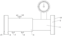
FIG. 1 is a schematic structural view of the present invention;
FIG. 2 is an enlarged view of portion A of FIG. 1 according to the present invention;
FIG. 3 is a front view of the present invention;
reference numerals: 1. a flowmeter body; 2. a second flange; 3. a connecting pipe; 4. a first flange; 5. a first filter plate; 6. a second filter plate; 7. a slag discharge pipe; 8. a valve; 9. a shaft lever; 10. cleaning the plate; 11. a cleaning brush; 12. rotating the rod; 13. a first bevel gear; 14. a second bevel gear; 15. a telescopic rod; 17. a first gasket; 18. a second gasket.
Detailed Description
In order to make the technical means, the original characteristics, the achieved purposes and the effects of the utility model easily understood, the utility model is further described below with reference to the specific embodiments and the attached drawings, but the following embodiments are only the preferred embodiments of the utility model, and not all embodiments. Based on the embodiments in the implementation, other embodiments obtained by those skilled in the art without any creative efforts belong to the protection scope of the present invention.
Specific embodiments of the present invention are described below with reference to the accompanying drawings.
Examples
As shown in fig. 1-3, a water injection flowmeter capable of remote data transmission comprises a flowmeter body 1, wherein a connecting pipe 3 is installed on the left side of the flowmeter body 1, a first flange 4 is fixedly connected to the left side of the connecting pipe 3, and a second flange 2 is installed on the right side of the flowmeter body 1; a first filter plate 5 and a second filter plate 6 are fixedly arranged in the connecting pipe 3, the size of the filter hole of the second filter plate 6 is smaller than that of the filter hole of the first filter plate 5, a shaft rod 9 is arranged in the connecting pipe 3, the shaft rod 9 penetrates through the first filter plate 5 and the second filter plate 6 and is rotationally connected with the first filter plate 5 and the second filter plate 6, two cleaning plates 10 are fixedly connected on the shaft rod 9, cleaning brushes 11 are arranged on the two cleaning plates 10, and the two cleaning brushes 11 are respectively contacted with the first filter plate 5 and the second filter plate 6; the connecting pipe 3 is provided with a driving mechanism for driving the shaft lever 9 to rotate.
In this embodiment, specifically, the driving mechanism includes a rotating rod 12, the rotating rod 12 penetrates through the top surface of the connecting pipe 3 and is rotatably connected with the connecting pipe 3, a first bevel gear 13 is fixedly connected to the lower end of the rotating rod 12, a second bevel gear 14 is engaged and connected to the first bevel gear 13, and the second bevel gear 14 is fixedly sleeved on the shaft rod 9; through setting up dwang 12, first bevel gear 13, second bevel gear 14, during the use, through rotating dwang 12, it is rotatory to drive first bevel gear 13, and then the meshing drives second bevel gear 14 rotatory, and then drives axostylus axostyle 9 rotatory.
In this embodiment, specifically, the part of the rotating rod 12 outside the connecting pipe 3 is fixedly connected with two telescopic rods 15, and the rotating rod 12 is made of stainless steel; through setting up telescopic link 15, during the use, through lengthening telescopic link 15, then at the telescopic link 15 after the rotation extension to rotation dwang 12 that can be laborsaving.
In this embodiment, specifically, two slag discharging pipes 7 are installed on the bottom surface of the connecting pipe 3 in a penetrating manner, valves 8 are installed on the two slag discharging pipes 7, and through the arrangement of the slag discharging pipes 7 and the valves 8, sundries in the connecting pipe 3 can be discharged conveniently.
In this embodiment, specifically, the first flange 4 is provided with a first gasket 17, and the second flange 2 is provided with a second gasket 18; the first gasket 17 is arranged, so that the first flange 4 is connected with the flange of the liquid injection pipeline more tightly; by providing the second gasket 18, the flange connection of the second flange 2 and the outlet pipe is made more tight.
In this embodiment, specifically, the first bevel gear 13 and the second bevel gear 14 have the same size, and both the first bevel gear 13 and the second bevel gear 14 are made of stainless steel, and are not easily rusted.
The working principle is as follows: when the liquid injection flowmeter is used specifically, the first flange 4 is connected with a flange of a liquid injection pipeline, the second flange 2 is connected with a flange of a liquid outlet pipeline, and then liquid flows through the connecting pipe 3 and the flowmeter body 1, so that the flowmeter body 1 collects the flow.
And the first filter 5 and the second filter 6 in the connecting pipe 3 can filter the liquid passing through the connecting pipe 3 in sequence, so as to filter out the impurities in the liquid, thereby avoiding the impurities from influencing the work of the flowmeter body 1.
When needs are to first filter 5, when second filter 6 cleans, through lengthening telescopic link 15, then telescopic link 15 after rotating the extension, and then drive dwang 12 and rotate, it is rotatory to drive first bevel gear 13, and then the meshing drives second bevel gear 14 rotatory, and then it is rotatory to drive axostylus axostyle 9, when the axostylus axostyle 9 is rotatory, can drive two cleaning plates 10 and rotate, and then drive two cleaning brushes 11 and rotate, and then make two cleaning brushes 11 to first filter 5, second filter 6 cleans, and then will adhere to first filter 5, debris on second filter 6 are got rid of, thereby filterable efficiency has been guaranteed. When stopping annotating the liquid, through opening two valves 8, discharge the debris that collect in the connecting pipe 3 through row sediment pipe 7 to avoid debris to pile up too much and influence the flow of liquid.
The foregoing shows and describes the general principles, essential features, and advantages of the utility model. It will be understood by those skilled in the art that the present invention is not limited to the embodiments described above, and the preferred embodiments of the present invention are described in the above embodiments and the description, and are not intended to limit the present invention. The scope of the utility model is defined by the appended claims and equivalents thereof.
Claims (6)
1. A water injection flowmeter capable of remote data transmission, comprising a flowmeter body (1), and is characterized in that: a connecting pipe (3) is installed on the left side of the flowmeter body (1), a first flange (4) is fixedly connected to the left side of the connecting pipe (3), and a second flange (2) is installed on the right side of the flowmeter body (1); a first filter plate (5) and a second filter plate (6) are fixedly arranged in the connecting pipe (3), the size of a filter hole of the second filter plate (6) is smaller than that of the first filter plate (5), a shaft rod (9) is arranged in the connecting pipe (3), the shaft rod (9) penetrates through the first filter plate (5) and the second filter plate (6) and is rotatably connected with the first filter plate (5) and the second filter plate (6), two cleaning plates (10) are fixedly connected to the shaft rod (9), cleaning brushes (11) are arranged on the two cleaning plates (10), and the two cleaning brushes (11) are respectively contacted with the first filter plate (5) and the second filter plate (6); and a driving mechanism for driving the shaft lever (9) to rotate is arranged on the connecting pipe (3).
2. The water flow meter capable of remote data transmission according to claim 1, wherein: actuating mechanism includes dwang (12), dwang (12) run through the top surface of connecting pipe (3) and rotate with connecting pipe (3) and be connected, the first bevel gear (13) of lower extreme fixedly connected with of dwang (12), the meshing is connected with second bevel gear (14) on first bevel gear (13), second bevel gear (14) fixed cover is established on axostylus axostyle (9).
3. The water flow meter capable of remote data transmission according to claim 2, wherein: dwang (12) are located two telescopic links of fixedly connected with (15) on the part outside connecting pipe (3), dwang (12) are stainless steel material.
4. The water flow meter capable of remote data transmission according to claim 1, wherein: two slag discharging pipes (7) are installed on the bottom surface of the connecting pipe (3) in a penetrating mode, and valves (8) are installed on the slag discharging pipes (7).
5. The water flow meter capable of remote data transmission according to claim 1, wherein: a first gasket (17) is arranged on the first flange (4), and a second gasket (18) is arranged on the second flange (2).
6. The water flow meter capable of remote data transmission according to claim 2, wherein: the first bevel gear (13) and the second bevel gear (14) are the same in size, and the first bevel gear (13) and the second bevel gear (14) are both made of stainless steel.
Priority Applications (1)
| Application Number | Priority Date | Filing Date | Title |
|---|---|---|---|
| CN202123155854.1U CN216342088U (en) | 2021-12-15 | 2021-12-15 | Water injection flowmeter capable of realizing remote data transmission |
Applications Claiming Priority (1)
| Application Number | Priority Date | Filing Date | Title |
|---|---|---|---|
| CN202123155854.1U CN216342088U (en) | 2021-12-15 | 2021-12-15 | Water injection flowmeter capable of realizing remote data transmission |
Publications (1)
| Publication Number | Publication Date |
|---|---|
| CN216342088U true CN216342088U (en) | 2022-04-19 |
Family
ID=81163940
Family Applications (1)
| Application Number | Title | Priority Date | Filing Date |
|---|---|---|---|
| CN202123155854.1U Active CN216342088U (en) | 2021-12-15 | 2021-12-15 | Water injection flowmeter capable of realizing remote data transmission |
Country Status (1)
| Country | Link |
|---|---|
| CN (1) | CN216342088U (en) |
-
2021
- 2021-12-15 CN CN202123155854.1U patent/CN216342088U/en active Active
Similar Documents
| Publication | Publication Date | Title |
|---|---|---|
| CN101417190B (en) | Turbid water filter automatic slag-draining device | |
| CN219744094U (en) | Filter equipment for sewage treatment | |
| CN111687146A (en) | Automatic scarfing cinder device of pipeline for hydraulic engineering | |
| CN219080536U (en) | Discharge cleaning device convenient to sewer line | |
| CN216342088U (en) | Water injection flowmeter capable of realizing remote data transmission | |
| CN217163464U (en) | New drum type microfilter device | |
| CN110987108A (en) | Water meter convenient for cleaning scale | |
| CN221535839U (en) | Filter back flush device | |
| CN112274988A (en) | Centrifugal pump filter belt cleaning device | |
| CN216935005U (en) | Sewage treatment system | |
| CN216170465U (en) | Back-washing internal-inflow fine grid | |
| CN222131114U (en) | Intelligent direct-current water filtering equipment | |
| CN220366875U (en) | Anti-blocking mechanism for coriolis force flowmeter | |
| CN208865287U (en) | A kind of self-cleaning active carbon filter | |
| CN219647079U (en) | Dust remover filter bucket | |
| CN207294390U (en) | A kind of waste water control device | |
| CN220715030U (en) | A filtering device suitable for sewage pipe | |
| CN220100145U (en) | Anti-blocking structure for water inlet of front pool of pump station | |
| CN221895898U (en) | A sewage pipe | |
| CN112044138A (en) | Sewage treatment plant with filtering capability based on environmental protection and environmental technology | |
| CN221230199U (en) | Novel rotary filter | |
| CN221171328U (en) | Gas pipeline drainage device | |
| CN219399270U (en) | Ponding structure is prevented to filtering capability | |
| CN220656589U (en) | Pollution discharge device capable of avoiding pipeline blockage | |
| CN217557119U (en) | Dredging sewage pipeline for municipal works |
Legal Events
| Date | Code | Title | Description |
|---|---|---|---|
| GR01 | Patent grant | ||
| GR01 | Patent grant |