CN216334887U - Feeding device for aluminum bar processing - Google Patents
Feeding device for aluminum bar processing Download PDFInfo
- Publication number
- CN216334887U CN216334887U CN202123220314.7U CN202123220314U CN216334887U CN 216334887 U CN216334887 U CN 216334887U CN 202123220314 U CN202123220314 U CN 202123220314U CN 216334887 U CN216334887 U CN 216334887U
- Authority
- CN
- China
- Prior art keywords
- fixed
- pressure controller
- fixedly arranged
- cylinder
- plate
- Prior art date
- Legal status (The legal status is an assumption and is not a legal conclusion. Google has not performed a legal analysis and makes no representation as to the accuracy of the status listed.)
- Active
Links
Images


Abstract
The utility model discloses an aluminum bar processing and feeding device, which relates to the technical field of aluminum bar processing and comprises a conveying frame, wherein an inclined plate is fixedly arranged on one side of the top end of the conveying frame, a supporting seat is fixedly arranged at the bottom end of the inclined plate, a storage bin is fixedly arranged on one side of the supporting seat, a material conveying assembly is arranged in the middle of the conveying frame, a feeding assembly is arranged in the storage bin, and supporting legs are fixedly arranged at four corners of the bottom end of the conveying frame: when the inside aluminium bar of storage silo slided to pressure controller's top, the aluminium bar card is between pressure controller and swash plate, the gravity extrusion pressure controller of aluminium bar self makes the piston rod extension of the first cylinder of pressure controller control, when pressure controller highly is higher than the height of swash plate, the aluminium bar slides in wherein two supporting blocks through the swash plate, the piston rod shrink of the first cylinder of control returns after the pressure on pressure controller top disappears simultaneously, thereby make the inside aluminium bar of storage silo automatic continuous material loading.
Description
Technical Field
The utility model relates to a feeding device, in particular to an aluminum bar processing feeding device, and belongs to the technical field of aluminum bar processing.
Background
The aluminium bar often needs to carry out the material loading through loading attachment in the course of working, loading attachment is the indispensable partly in automatic system, in the production line of aluminium bar processing, often put the aluminium bar on loading attachment's conveyer belt, utilize the conveyer belt to transmit the aluminium bar, but current loading attachment is in transmission process, the conveyer belt often takes place the off tracking dislocation phenomenon because of cylinder wearing and tearing or aluminium bar placement mistake, lead to the material loading in-process need constantly change loading attachment, and traditional loading attachment needs a great deal of staff to carry out the material loading, because the aluminium bar surface is comparatively smooth, the material loading is very inconvenient.
SUMMERY OF THE UTILITY MODEL
The utility model aims to provide a feeding device for aluminum bar processing, which solves the problems that a conveying belt of a traditional feeding device provided in the background art is easy to deviate and misplace, and the feeding is inconvenient due to the smooth surface of an aluminum bar.
In order to achieve the purpose, the utility model provides the following technical scheme: the utility model provides an aluminium bar processing loading attachment, includes the carriage, the fixed swash plate that is equipped with in one side on carriage top, the bottom mounting of swash plate is equipped with the supporting seat, the fixed storage silo that is equipped with in one side of supporting seat, the middle part of carriage is equipped with defeated material subassembly, the inside of storage silo is equipped with the material loading subassembly, the four corners of carriage bottom is all fixed and is equipped with the stabilizer blade, the fixed accessory plate that is equipped with in middle part of the inside bottom of carriage.
Preferably, defeated material subassembly includes four bearings, two pivots, two conveying rollers, conveyer belt and driving motor, four the bearing is fixed respectively and sets up the inner wall in the positive both sides of carriage and the inner wall of back both sides, and every two are relative all rotate between the bearing and be connected with the pivot, two the surface of pivot is all fixed and is equipped with the conveying roller, two the transmission is connected with the conveyer belt between the conveying roller, driving motor is fixed to be set up in the positive one side of carriage, driving motor's transmission shaft and the one end fixed connection of one of them pivot.
Preferably, the material loading subassembly includes baffle, spout, slide, first cylinder and pressure controller, the fixed middle part that sets up at the storage silo of baffle, the inner wall in storage silo one side is seted up to the spout, the inner wall sliding connection of spout has the slide, the fixed first cylinder that is equipped with in one side of storage silo bottom, the piston rod of first cylinder and the bottom fixed connection of slide, the fixed top that sets up at the storage silo opposite side of pressure controller, the fixed top that sets up at the slide of detection end of pressure controller, first cylinder passes through pressure controller and power electric connection.
Preferably, a second cylinder is fixedly arranged at the top end of the auxiliary plate, a connecting rod is fixedly connected to a piston rod of the second cylinder, and two tensioning wheels are rotatably connected to the top end of the connecting rod.
Preferably, the both sides of connecting rod are all fixed and are equipped with a plurality of fixture block, the both sides of the inside bottom of carriage are all fixed and are equipped with the limiting plate, two the top of limiting plate one side is all fixed and is equipped with the slide rail, two the equal sliding connection of inner wall of slide rail has the slider, two one side of slider is all fixed and is equipped with reset spring, two reset spring's one end respectively with two limiting plate fixed connection.
Preferably, the cavity has been seted up at the middle part of conveyer belt, the both sides side of conveyer belt all is fixed and is equipped with the supporting shoe that a plurality of equidistance set up, a plurality of the supporting shoe is made for the rubber material.
Preferably, a switch panel is fixedly arranged in the middle of the other side of the storage bin, a driving motor switch and a second cylinder switch are respectively arranged on the surface of the switch panel, and the driving motor and the second cylinder are respectively electrically connected with a power supply through the driving motor switch and the second cylinder switch.
Compared with the prior art, the aluminum bar processing and feeding device provided by the utility model has the following beneficial effects:
1. when the aluminum bar in the storage bin slides to the top end of the pressure controller, the aluminum bar is clamped between the pressure controller and the inclined plate, the gravity of the aluminum bar extrudes the pressure controller to enable the pressure controller to control the piston rod of the first cylinder to extend, when the height of the pressure controller is higher than that of the inclined plate, the aluminum bar slides into two of the supporting blocks close to the inclined plate through the inclined plate, and meanwhile, after the pressure at the top end of the pressure controller disappears, the piston rod of the first cylinder is controlled to contract and recover, so that the aluminum bar in the storage bin is automatically and continuously fed;
2. the second cylinder contracts to drive the connecting rod and the two tensioning wheels to move downwards, the two sliding blocks respectively slide on the inner walls of the two sliding rails after being extruded by the two clamping blocks, the two reset springs contract, the two tensioning wheels extrude the bottom of the conveying belt to tighten the conveying belt, the two reset springs reset to push the two sliding blocks to move, and the two sliding blocks respectively extrude the other two clamping blocks to fix the heights of the two tensioning wheels;
3. the aluminum bar is limited by the supporting blocks, so that the stability of the aluminum bar in the conveying process is effectively improved.
Drawings
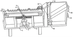
FIG. 1 is a schematic structural view of the present invention;
FIG. 2 is a schematic cross-sectional view of the present invention;
FIG. 3 is a schematic structural view of a carriage according to the present invention;
fig. 4 is an enlarged schematic view of the structure at a in fig. 2 according to the present invention.
In the figure: 1. a carriage; 2. a sloping plate; 3. a supporting seat; 4. a storage bin; 5. a material conveying component; 6. a feeding assembly; 7. an auxiliary plate; 8. a second cylinder; 9. a connecting rod; 10. a tension wheel; 11. a clamping block; 12. a limiting plate; 13. a slide rail; 14. a slider; 15. a return spring; 16. a cavity; 17. a support block; 18. a switch panel; 19. a support leg; 51. a bearing; 52. a rotating shaft; 53. a conveying roller; 54. a conveyor belt; 55. a drive motor; 61. a partition plate; 62. a chute; 63. a slide plate; 64. a first cylinder; 65. a pressure controller.
Detailed Description
The technical solutions in the embodiments of the present invention will be clearly and completely described below with reference to the drawings in the embodiments of the present invention, and it is obvious that the described embodiments are only a part of the embodiments of the present invention, and not all of the embodiments. All other embodiments, which can be derived by a person skilled in the art from the embodiments given herein without making any creative effort, shall fall within the protection scope of the present invention.
Example 1:
referring to fig. 1-4, the utility model provides an aluminum bar processing and feeding device, which comprises a conveying frame 1, wherein an inclined plate 2 is fixedly arranged on one side of the top end of the conveying frame 1, a supporting seat 3 is fixedly arranged at the bottom end of the inclined plate 2, a storage bin 4 is fixedly arranged on one side of the supporting seat 3, a material conveying assembly 5 is arranged in the middle of the conveying frame 1, a feeding assembly 6 is arranged inside the storage bin 4, supporting legs 19 are fixedly arranged at four corners of the bottom end of the conveying frame 1, and an auxiliary plate 7 is fixedly arranged in the middle of the bottom end inside the conveying frame 1;
a second cylinder 8 is fixedly arranged at the top end of the auxiliary plate 7, a connecting rod 9 is fixedly connected to a piston rod of the second cylinder 8, and two tensioning wheels 10 are rotatably connected to the top end of the connecting rod 9;
a plurality of clamping blocks 11 are fixedly arranged on two sides of the connecting rod 9, limiting plates 12 are fixedly arranged on two sides of the bottom end inside the conveying frame 1, sliding rails 13 are fixedly arranged on the tops of one sides of the two limiting plates 12, sliding blocks 14 are slidably connected to the inner walls of the two sliding rails 13, return springs 15 are fixedly arranged on one sides of the two sliding blocks 14, and one ends of the two return springs 15 are fixedly connected with the two limiting plates 12 respectively;
the middle part of the other side of the storage bin 4 is fixedly provided with a switch panel 18, the surface of the switch panel 18 is provided with a second cylinder switch, and the second cylinder 8 is electrically connected with a power supply through the second cylinder switch.
Example 2:
the material conveying assembly 5 comprises four bearings 51, two rotating shafts 52, two conveying rollers 53, a conveying belt 54 and a driving motor 55, wherein the four bearings 51 are respectively and fixedly arranged on the inner walls of the two sides of the front surface and the inner walls of the two sides of the back surface of the conveying frame 1, the rotating shafts 52 are respectively and rotatably connected between every two opposite bearings 51, the conveying rollers 53 are respectively and fixedly arranged on the surfaces of the two rotating shafts 52, the conveying belt 54 is in transmission connection between the two conveying rollers 53, the driving motor 55 is fixedly arranged on one side of the front surface of the conveying frame 1, and a transmission shaft of the driving motor 55 is fixedly connected with one end of one rotating shaft 52;
the middle part of the conveying belt 54 is provided with a cavity 16, a plurality of supporting blocks 17 which are arranged at equal intervals are fixedly arranged on both sides of the conveying belt 54, and the supporting blocks 17 are all made of rubber;
a switch panel 18 is fixedly arranged in the middle of the other side of the storage bin 4, a driving motor switch is arranged on the surface of the switch panel 18, and a driving motor 55 is electrically connected with a power supply through the driving motor switch;
specifically, as shown in fig. 1, 2 and 3, first, a driving motor switch on the surface of the switch panel 18 is turned on, the driving motor 55 is started to drive one of the rotating shafts 52 and one of the conveying rollers 53 to rotate, and one of the conveying rollers 53 rotates to drive the conveying belt 54 between the two conveying rollers 53, so as to convey the aluminum bars at the top ends of the plurality of supporting blocks 17.
Example 3:
the feeding assembly 6 comprises a partition plate 61, a chute 62, a sliding plate 63, a first cylinder 64 and a pressure controller 65, the partition plate 61 is fixedly arranged in the middle of the storage bin 4, the chute 62 is arranged on the inner wall of one side of the storage bin 4, the sliding plate 63 is connected to the inner wall of the chute 62 in a sliding manner, the first cylinder 64 is fixedly arranged on one side of the bottom end of the storage bin 4, a piston rod of the first cylinder 64 is fixedly connected with the bottom end of the sliding plate 63, the pressure controller 65 is fixedly arranged on the top of the other side of the storage bin 4, a detection end of the pressure controller 65 is fixedly arranged on the top end of the sliding plate 63, and the first cylinder 64 is electrically connected with a power supply through the pressure controller 65;
specifically, as shown in fig. 1 and 2, firstly, when the aluminum rod inside the storage bin 4 slides to the top end of the pressure controller 65, the aluminum rod is clamped between the pressure controller 65 and the inclined plate 2, the gravity of the aluminum rod extrudes the pressure controller 65 to enable the pressure controller 65 to control the piston rod of the first cylinder 64 to extend, when the height of the pressure controller 65 is higher than that of the inclined plate 2, the aluminum rod slides into two of the supporting blocks 17 close to the inclined plate 2 through the inclined plate 2, and simultaneously, after the pressure at the top end of the pressure controller 65 disappears, the piston rod of the first cylinder 64 is controlled to contract and recover, so that the aluminum rod inside the storage bin 4 is continuously fed.
The working principle is as follows: when the aluminum bar processing and feeding device is used, firstly, the detection range of a pressure controller 65 with the model number of D502-7D is set to be the weight of a single aluminum bar to be fed, then the aluminum bar to be fed is placed in a storage bin 4, when the height of the aluminum bar is higher than that of the pressure controller 65, the aluminum bar at the topmost end in the storage bin 4 rolls to the top end of the pressure controller 65 due to the self gravity, then a driving motor switch on the surface of a switch panel 18 is turned on, the gravity of the aluminum bar extrudes the pressure controller 65 to enable the pressure controller 65 to control a piston rod of a first air cylinder 64 to extend, when the height of the pressure controller 65 is higher than that of an inclined plate 2, the aluminum bar slides into two supporting blocks 17 close to the inclined plate 2 through the inclined plate 2, and simultaneously, after the pressure at the top end of the pressure controller 65 disappears, the piston rod of the first air cylinder 64 is controlled to shrink and recover, so that the aluminum bar in the storage bin 4 is continuously fed, meanwhile, the driving motor 55 is started to drive one of the rotating shafts 52 and one of the conveying rollers 53 to rotate, one of the conveying rollers 53 rotates to drive the conveying belt 54 between the two conveying rollers 53, thereby conveying the aluminum bars at the top ends of the plurality of supporting blocks 17, when the conveyer belt 54 is loosened to affect feeding after the device is used for a long time, the second air cylinder switch on the surface of the switch panel 18 is opened, the second air cylinder 8 contracts to drive the connecting rod 9 and the two tension pulleys 10 to move downwards, meanwhile, the two sliding blocks 14 are extruded by the two clamping blocks 11 and then respectively slide on the inner walls of the two sliding rails 13, meanwhile, the two return springs 15 contract, the two tension pulleys 10 press the bottom of the conveying belt 54 to tighten the conveying belt 54, the two return springs 15 return to push the two sliders 14 to move, and the two sliders 14 respectively press the other two clamping blocks 11 to fix the heights of the two tension pulleys 10.
Although embodiments of the present invention have been shown and described, it will be appreciated by those skilled in the art that changes, modifications, substitutions and alterations can be made in these embodiments without departing from the principles and spirit of the utility model, the scope of which is defined in the appended claims and their equivalents.
Claims (7)
1. The utility model provides an aluminium bar processing loading attachment, includes carriage (1), its characterized in that, one side of carriage (1) top is fixed and is equipped with swash plate (2), the bottom mounting of swash plate (2) is equipped with supporting seat (3), one side of supporting seat (3) is fixed and is equipped with storage silo (4), the middle part of carriage (1) is equipped with defeated material subassembly (5), the inside of storage silo (4) is equipped with material loading subassembly (6), the four corners of carriage (1) bottom all is fixed and is equipped with stabilizer blade (19), the middle part of the inside bottom of carriage (1) is fixed and is equipped with accessory plate (7).
2. The aluminum bar processing and feeding device of claim 1, wherein: defeated material subassembly (5) are including four bearings (51), two pivot (52), two conveying roller (53), conveyer belt (54) and driving motor (55), four bearing (51) are fixed respectively and are set up at the inner wall of carriage (1) front both sides and the inner wall of back both sides, and every two are relative all rotate between bearing (51) and be connected with pivot (52), two the surface of pivot (52) is all fixed and is equipped with conveying roller (53), two the transmission is connected with conveyer belt (54) between conveying roller (53), driving motor (55) are fixed to be set up in carriage (1) positive one side, the transmission shaft of driving motor (55) and the one end fixed connection of one of them pivot (52).
3. The aluminum bar processing and feeding device of claim 1, wherein: the feeding assembly (6) comprises a partition plate (61), a sliding groove (62), a sliding plate (63), a first air cylinder (64) and a pressure controller (65), the partition plate (61) is fixedly arranged at the middle part of the storage bin (4), the sliding groove (62) is arranged on the inner wall of one side of the storage bin (4), the sliding plate (63) is connected to the inner wall of the sliding groove (62), the first air cylinder (64) is fixedly arranged on one side of the bottom end of the storage bin (4), a piston rod of the first air cylinder (64) is fixedly connected with the bottom end of the sliding plate (63), the pressure controller (65) is fixedly arranged at the top of the other side of the storage bin (4), the top end of the sliding plate (63) is fixedly arranged at the detection end of the pressure controller (65), and the first air cylinder (64) is electrically connected with a power supply through the pressure controller (65).
4. The aluminum bar processing and feeding device of claim 2, wherein: a second cylinder (8) is fixedly arranged at the top end of the auxiliary plate (7), a connecting rod (9) is fixedly connected to a piston rod of the second cylinder (8), and two tensioning wheels (10) are rotatably connected to the top end of the connecting rod (9).
5. The aluminum bar processing and feeding device of claim 4, wherein: the both sides of connecting rod (9) are all fixed and are equipped with a plurality of fixture block (11), the both sides of carriage (1) inside bottom are all fixed and are equipped with limiting plate (12), two the top of limiting plate (12) one side is all fixed and is equipped with slide rail (13), two the equal sliding connection of inner wall of slide rail (13) has slider (14), two one side of slider (14) is all fixed and is equipped with reset spring (15), two the one end of reset spring (15) respectively with two limiting plate (12) fixed connection.
6. The aluminum bar processing and feeding device of claim 2, wherein: the middle part of the conveying belt (54) is provided with a cavity (16), a plurality of supporting blocks (17) which are arranged at equal intervals are fixedly arranged on the two sides of the conveying belt (54), and the supporting blocks (17) are all made of rubber materials.
7. The aluminum bar processing and feeding device of claim 4, wherein: the middle part of the other side of the storage bin (4) is fixedly provided with a switch panel (18), the surface of the switch panel (18) is respectively provided with a driving motor switch and a second cylinder switch, and the driving motor (55) and the second cylinder (8) are respectively electrically connected with a power supply through the driving motor switch and the second cylinder switch.
Priority Applications (1)
| Application Number | Priority Date | Filing Date | Title |
|---|---|---|---|
| CN202123220314.7U CN216334887U (en) | 2021-12-21 | 2021-12-21 | Feeding device for aluminum bar processing |
Applications Claiming Priority (1)
| Application Number | Priority Date | Filing Date | Title |
|---|---|---|---|
| CN202123220314.7U CN216334887U (en) | 2021-12-21 | 2021-12-21 | Feeding device for aluminum bar processing |
Publications (1)
| Publication Number | Publication Date |
|---|---|
| CN216334887U true CN216334887U (en) | 2022-04-19 |
Family
ID=81165322
Family Applications (1)
| Application Number | Title | Priority Date | Filing Date |
|---|---|---|---|
| CN202123220314.7U Active CN216334887U (en) | 2021-12-21 | 2021-12-21 | Feeding device for aluminum bar processing |
Country Status (1)
| Country | Link |
|---|---|
| CN (1) | CN216334887U (en) |
Cited By (1)
| Publication number | Priority date | Publication date | Assignee | Title |
|---|---|---|---|---|
| CN115876051A (en) * | 2023-03-08 | 2023-03-31 | 临沂金正阳管业有限公司 | Outer diameter detection equipment for manufacturing seamless steel pipe |
-
2021
- 2021-12-21 CN CN202123220314.7U patent/CN216334887U/en active Active
Cited By (1)
| Publication number | Priority date | Publication date | Assignee | Title |
|---|---|---|---|---|
| CN115876051A (en) * | 2023-03-08 | 2023-03-31 | 临沂金正阳管业有限公司 | Outer diameter detection equipment for manufacturing seamless steel pipe |
Similar Documents
| Publication | Publication Date | Title |
|---|---|---|
| CN210824146U (en) | Conveyor for cement manufacture | |
| CN216334887U (en) | Feeding device for aluminum bar processing | |
| CN110615305A (en) | Braided bag material loading conveyor | |
| CN215755011U (en) | Large-storage-capacity stack cache device | |
| CN209758344U (en) | Belt feeder bracket whereabouts formula groove bearing roller | |
| CN109623389B (en) | A transportation forming device for electronic product shell board | |
| CN215624972U (en) | Logistics supply chain is with storage conveyer that prevents goods and roll down | |
| CN212881785U (en) | Bidirectional feeding and discharging device of cold press | |
| CN209871456U (en) | Drum-type conveyor with adjusting function | |
| CN210593859U (en) | Steel sheet processing conveying equipment | |
| CN210876796U (en) | Extrusion forming device | |
| CN110842549B (en) | Intelligent flexible assembly production line | |
| CN109834923B (en) | Reduce artifical material loading cost's high-efficient type plastic board knurling equipment | |
| CN112061841A (en) | Production device and production process of preservative film | |
| CN217050424U (en) | Auxiliary feeding device of plastic bag production equipment | |
| CN216732632U (en) | Novel hang boiling hot board mould | |
| CN215755052U (en) | Turnover discharging device for formed parts | |
| CN220097439U (en) | Aluminum bar loading and unloading device | |
| CN219949380U (en) | Roller conveying line | |
| CN218024237U (en) | Ornamental strip unloader and buffer memory material feeding unit thereof | |
| CN215325694U (en) | Compound fertilizer flattening device on compound fertilizer production line | |
| CN220299529U (en) | Material conveying device convenient for discharging during loading | |
| CN217534336U (en) | Dirty conveyer belt of excrement | |
| CN219884912U (en) | Inventory handling conveying rack | |
| CN217920078U (en) | Logistics conveying is with concatenation formula horizontal belt feeder convenient to adjust direction |
Legal Events
| Date | Code | Title | Description |
|---|---|---|---|
| GR01 | Patent grant | ||
| GR01 | Patent grant |