CN216329542U - Full-automatic rotational molding rotary forming device - Google Patents
Full-automatic rotational molding rotary forming device Download PDFInfo
- Publication number
- CN216329542U CN216329542U CN202123123828.0U CN202123123828U CN216329542U CN 216329542 U CN216329542 U CN 216329542U CN 202123123828 U CN202123123828 U CN 202123123828U CN 216329542 U CN216329542 U CN 216329542U
- Authority
- CN
- China
- Prior art keywords
- rotating
- bevel gear
- side wall
- spline
- rotating arm
- Prior art date
- Legal status (The legal status is an assumption and is not a legal conclusion. Google has not performed a legal analysis and makes no representation as to the accuracy of the status listed.)
- Active
Links
Images


Abstract
The utility model discloses a full-automatic rotational molding rotary forming device, wherein a driving assembly drives a rotating arm to rotate, the rotating arm drives two rotating assemblies to rotate in the front-back direction, and the driving assembly drives a mold to rotate in the left-right opposite direction through a first spline sleeve, a spline shaft, a second spline sleeve, a fixing plate and a support, so that raw materials in an inner cavity of the mold can be rotationally formed under the heating condition; make two upper and lower moulds open and shut through push-and-pull subassembly, reinforced or get when material convenient, swift, labour saving and time saving, the mould passes through bolted connection on the support simultaneously, easy dismounting, change, maintenance convenience.
Description
Technical Field
The utility model relates to the technical field of rotational molding devices, in particular to a full-automatic rotational molding rotary forming device.
Background
The basic process of rotational molding is simple by placing a powdered or liquid polymer in a mold, heating the polymer while the mold rotates and revolves around a vertical axis, and then cooling and molding the polymer. At the beginning of the heating stage, if a powdery material is used, a porous layer is formed on the surface of the die, then the porous layer is gradually melted along with the circulation process, and finally a homogeneous layer with uniform thickness is formed; if a liquid material is used, it flows and coats the mold surface first, and stops flowing completely when the gel point is reached. The mold is then transferred to a cooling station where it is cooled by forced air or water spray, the mold is then opened and the finished part is removed and the next cycle is performed.
The existing rotational molding and rotational molding device is mostly inconvenient to open and close or replace a mold, complex in operation, time and labor consuming, and capable of reducing working efficiency, and a plurality of motors are used for transmission, so that the device cost is increased.
SUMMERY OF THE UTILITY MODEL
In view of the above problems, the present invention provides a full-automatic rotational molding device, which solves the problems in the background art.
In order to achieve the above object, the present invention adopts the following technical solutions:
a full-automatic rotational molding rotary forming device comprises a base, wherein a support cylinder is connected to the top of the base, a rotary arm is connected to the left side wall and the right side wall of the support cylinder, a box body is connected to the left end of the rotary arm, rotary assemblies are symmetrically arranged on the upper side and the lower side of the box body and comprise frames, the side walls of opposite ends of the frames are connected with the corresponding side walls of the box body, first spline sleeves are symmetrically connected to the top and the bottom of the frames, supporting rods are symmetrically connected to the upper side and the lower side of the inner side walls of the frames, the opposite ends of the first spline sleeves penetrate through the corresponding supporting rods and are connected with spline shafts, the opposite ends of the spline shafts are connected with second spline sleeves, and the second spline sleeves are connected with fixed plates;
the opposite ends of the fixed plate are symmetrically connected with brackets at the left and right sides, the inner side walls of the brackets are connected with dies through bolts, and connecting components are arranged between the brackets which correspond up and down; push-pull components are symmetrically arranged on the upper part and the lower part of the inner side wall of the frame and are matched with the second spline sleeve; a driving assembly is arranged in the inner cavity of the support cylinder, and the driving assembly is matched with the rotating arm and the first spline sleeve.
Preferably, the driving assembly comprises a motor, the motor is connected to the inner cavity of the support cylinder through a partition plate, and the output end of the motor is connected with a first bevel gear; the side wall of the rotating arm is connected with a second bevel gear, and the first bevel gear is meshed with the second bevel gear; the output end of the motor is matched with the first spline housing through the transmission assembly.
Preferably, the transmission assembly comprises a rotating rod, the rotating rod is connected to the right side wall of the support cylinder through a bearing seat, and the side wall of the rotating rod is connected with a first belt pulley and a third bevel gear; the output end of the motor is connected with a second belt pulley, and a belt is connected between the second belt pulley and the first belt pulley; the left side wall and the right side wall of the rotating arm are connected with rotating shafts, the left end and the right end of each rotating shaft are connected with fourth bevel gears, the fourth bevel gear on the left side is positioned in the inner cavity of the box body, and the fourth bevel gear on the right side is meshed with the third bevel gear; the top and the bottom of the inner cavity of the box body are both connected with a fifth bevel gear through rotating rollers, the fifth bevel gear is meshed with a fourth bevel gear on the left side, and one end of each rotating roller, which is far away from each other, is connected with a corresponding first spline housing.
Preferably, the connecting assembly comprises clamping blocks, and the clamping blocks are respectively connected to the side walls of the opposite ends of the bracket far away from the rotating arm in a bilateral symmetry manner; the opposite ends of the bracket close to the rotating arm are respectively connected with a clamping rod, and the other end of the clamping rod extends into the space between the two corresponding clamping blocks.
Preferably, the push-pull assembly comprises electric telescopic rods, and the electric telescopic rods are connected to the top and the bottom of the inner cavity of the frame; the side wall of the second spline sleeve is connected with a rotating ring, and the telescopic end of the electric telescopic rod is connected with the corresponding rotating ring.
The utility model has the beneficial effects that:
1. according to the device, the rotating arm is driven to rotate by the driving assembly, the rotating arm drives the two rotating assemblies to rotate in the front-back direction, and meanwhile, the driving assembly drives the die to rotate in the left-right opposite direction through the first spline sleeve, the spline shaft, the second spline sleeve, the fixing plate and the bracket, so that the raw materials in the inner cavity of the die can be rotationally molded under the heating condition;
2. according to the utility model, the upper die and the lower die are opened and closed through the push-pull assembly, so that feeding or taking is convenient, rapid, time-saving and labor-saving, and meanwhile, the dies are connected to the support through bolts, so that the assembly and disassembly are convenient, and the replacement, maintenance and maintenance are convenient.
Drawings
FIG. 1 is a schematic structural view of the apparatus;
FIG. 2 is a partial left side view of the present device;
FIG. 3 is an enlarged view taken at A in FIG. 1;
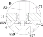
FIG. 4 is an enlarged view at B of FIG. 1;
in the figure: 1-base, 2-support cylinder, 3-rotating arm, 4-box, 5-rotating component, 51-frame, 53-first spline housing, 54-support rod, 55-spline shaft, 56-second spline housing, 57-fixing plate, 58-support, 59-mould, 6-connecting component, 61-clamping block, 62-clamping rod, 7-push-pull component, 71-electric telescopic rod, 72-rotating ring, 8-driving component, 81-motor, 82-partition plate, 83-first bevel gear, 84-second bevel gear, 85-transmission component, 851-rotating rod, 852-first belt pulley, 853-third bevel gear, 854-second belt pulley, 855-belt, 856-rotating shaft, 857-fourth bevel gear, 858-rotating rollers, 859-fifth bevel gears.
Detailed Description
In order to make the objects, technical solutions and advantages of the embodiments of the present invention clearer, the technical solutions in the embodiments of the present invention will be clearly and completely described below with reference to the embodiments of the present invention. All other embodiments, which can be derived by a person skilled in the art from the embodiments of the present invention without any inventive step, are within the scope of the present invention.
In the description of the present invention, it should be noted that, as the terms "center", "upper", "lower", "left", "right", "vertical", "horizontal", "inner", "outer", etc. appear, their indicated orientations or positional relationships are based on those shown in the drawings, and are only for convenience of description and simplicity of description, but do not indicate or imply that the referred device or element must have a specific orientation, be constructed in a specific orientation, and be operated, and thus, should not be construed as limiting the present invention. Moreover, the terms "first," "second," and "third," if any, are used for descriptive purposes only and are not to be construed as indicating or implying relative importance.
In the description of the present invention, it is to be noted that, unless otherwise explicitly specified or limited, the terms "mounted," "connected," and "connected" should be interpreted broadly, e.g., as meaning either a fixed connection, a removable connection, or an integral connection; can be mechanically or electrically connected; they may be connected directly or indirectly through intervening media, or they may be interconnected between two elements. The specific meanings of the above terms in the present invention can be understood in specific cases to those skilled in the art.
With reference to fig. 1-4, the utility model provides a technical scheme, a full-automatic rotational molding rotary forming device, which comprises a base 1, wherein a support cylinder 2 is fixedly connected to the top of the base 1, a rotary arm 3 is rotatably connected to the left side wall and the right side wall of the support cylinder 2, a box body 4 is fixedly connected to the left end of the rotary arm 3, rotary assemblies 5 are symmetrically arranged on the upper side and the lower side of the box body 4, each rotary assembly 5 comprises a frame 51, the side wall of the opposite end of the frame 51 is fixedly connected to the corresponding side wall of the box body 4, the top and the bottom of the frame 51 are symmetrically and rotatably connected with a first spline housing 53, support rods 54 are symmetrically and fixedly connected to the upper side and the lower side of the inner side wall of the frame 51, the opposite end of the first spline housing 53 penetrates through the corresponding support rod 54 and is inserted with a spline shaft 55, the opposite end of the spline shaft 55 is fixedly connected with a second spline housing 56, and the second spline housing 56 is fixedly connected with a fixing plate 57;
The driving assembly 8 comprises a motor 81, the motor 81 is fixedly connected to the inner cavity of the support cylinder 2 through a partition plate 82, and the output end of the motor 81 is fixedly connected with a first bevel gear 83; a second bevel gear 84 is fixedly connected to the side wall of the rotating arm 3, and a first bevel gear 83 is meshed with the second bevel gear 84; the output of the motor 81 is coupled to the first splined hub 53 via a gearing assembly 85.
The transmission assembly 85 comprises a rotating rod 851, the rotating rod 851 is rotatably connected to the right side wall of the support cylinder 2 through a bearing seat, and the side wall of the rotating rod 851 is fixedly connected with a first belt pulley 852 and a third bevel gear 853; the output end of the motor 81 is fixedly connected with a second belt pulley 854, and a belt 855 is sleeved between the second belt pulley 854 and the first belt pulley 852; a rotating shaft 856 is rotatably connected to the left side wall and the right side wall of the rotating arm 3, a fourth bevel gear 857 is fixedly connected to the left end and the right end of the rotating shaft 856, the fourth bevel gear 857 on the left side is located in the inner cavity of the box body 4, and the fourth bevel gear 857 on the right side is meshed with the third bevel gear 853; the top and the bottom of the inner cavity of the box body 4 are rotatably connected with a fifth bevel gear 859 through a rotating roller 858, the fifth bevel gear 859 is meshed with a fourth bevel gear 857 on the left side, and one end, which is far away from the rotating roller 858, is fixedly connected with the corresponding first spline housing 53.
Wherein, the connecting assembly 6 comprises clamping blocks 61, and the clamping blocks 61 are respectively and bilaterally symmetrically fixedly connected to the side wall of the opposite end of the bracket 58 far away from the rotating arm 3; the opposite ends of the bracket 58 near the rotating arm 3 are respectively fixedly connected with a clamping rod 62, and the other end of the clamping rod 62 extends into between the two corresponding clamping blocks 61.
The push-pull assembly 7 comprises an electric telescopic rod 71, and the electric telescopic rod 71 is fixedly connected to the top and the bottom of an inner cavity of the frame 51; the side walls of the second spline sleeves 56 are rotatably connected with rotating rings 72, and the telescopic ends of the electric telescopic rods 71 are fixedly connected with the corresponding rotating rings 72.
One specific application of this embodiment is:
the push-pull assembly 7 drives the die 59 to separate, the raw materials are poured into the inner cavity of the die 59, the push-pull assembly 7 closes the die 59, the clamping rod 62 extends between the two corresponding clamping blocks 61, the driving assembly 8 drives the rotating arm 3 to rotate, the rotating arm 3 drives the two rotating assemblies 5 to rotate in the front-back direction, meanwhile, the driving assembly 8 drives the die 59 to rotate in the left-right direction through the first spline housing 53, the spline shaft 55, the second spline housing 56, the fixing plate 57 and the bracket 58, and the raw materials in the inner cavity of the die 59 are formed in a rotating mode under the heating condition;
after the mold 59 is cooled, the push-pull assembly 7 can drive the mold 59 to separate, and then the molded rotational molding part is taken out.
The electric elements adopted by the patent are all sold in the market, and the specific structure and the control mode are not repeated in the specification.
The above examples are only intended to illustrate the technical solution of the present invention, but not to limit it; although the present invention has been described in detail with reference to the foregoing embodiments, it will be understood by those of ordinary skill in the art that: the technical solutions described in the foregoing embodiments may still be modified, or some technical features may be equivalently replaced; and such modifications or substitutions do not depart from the spirit and scope of the corresponding technical solutions of the embodiments of the present invention.
Claims (5)
1. The utility model provides a full-automatic rotational moulding device, includes base (1), its characterized in that: the top of the base (1) is connected with a support cylinder (2), the left side wall and the right side wall of the support cylinder (2) are connected with a rotating arm (3), the left end of the rotating arm (3) is connected with a box body (4), rotating assemblies (5) are symmetrically arranged on the upper side and the lower side of the box body (4), each rotating assembly (5) comprises a frame (51), the side wall of the opposite end of each frame (51) is connected with the corresponding side wall of the box body (4), the top and the bottom of each frame (51) are symmetrically connected with a first spline sleeve (53), the inner side wall of each frame (51) is vertically symmetrically connected with supporting rods (54), the opposite end of each first spline sleeve (53) penetrates through the corresponding supporting rod (54) and is connected with a spline shaft (55), the opposite end of each spline shaft (55) is connected with a second spline sleeve (56), and each second spline sleeve (56) is connected with a fixing plate (57);
the opposite ends of the fixed plate (57) are symmetrically connected with brackets (58) left and right, the inner side walls of the brackets (58) are connected with dies (59) through bolts, and connecting assemblies (6) are arranged between the brackets (58) which correspond up and down; the push-pull components (7) are symmetrically arranged on the upper portion and the lower portion of the inner side wall of the frame (51), and the push-pull components (7) are matched with the second spline sleeve (56); a driving assembly (8) is arranged in the inner cavity of the support cylinder (2), and the driving assembly (8) is matched with the rotating arm (3) and the first spline sleeve (53).
2. The full-automatic rotational molding device according to claim 1, characterized in that: the driving assembly (8) comprises a motor (81), the motor (81) is connected to the inner cavity of the support cylinder (2) through a partition plate (82), and the output end of the motor (81) is connected with a first bevel gear (83); the side wall of the rotating arm (3) is connected with a second bevel gear (84), and the first bevel gear (83) is meshed with the second bevel gear (84); the output end of the motor (81) is matched with the first spline housing (53) through a transmission assembly (85).
3. The full-automatic rotational molding device according to claim 2, characterized in that: the transmission assembly (85) comprises a rotating rod (851), the rotating rod (851) is connected to the right side wall of the support cylinder (2) through a bearing seat, and the side wall of the rotating rod (851) is connected with a first belt pulley (852) and a third bevel gear (853); the output end of the motor (81) is connected with a second belt pulley (854), and a belt (855) is connected between the second belt pulley (854) and the first belt pulley (852); the left side wall and the right side wall of the rotating arm (3) are connected with a rotating shaft (856), the left end and the right end of the rotating shaft (856) are both connected with a fourth bevel gear (857), the fourth bevel gear (857) on the left side is positioned in the inner cavity of the box body (4), and the fourth bevel gear (857) on the right side is meshed with the third bevel gear (853); the top and the bottom of the inner cavity of the box body (4) are connected with a fifth bevel gear (859) through a rotating roller (858), the fifth bevel gear (859) is meshed with a fourth bevel gear (857) on the left side, and one end, away from each other, of the rotating roller (858) is connected with a corresponding first spline housing (53).
4. The full-automatic rotational molding device according to claim 1, characterized in that: the connecting assembly (6) comprises clamping blocks (61), and the clamping blocks (61) are respectively connected to the side walls of the opposite ends of the bracket (58) far away from the rotating arm (3) in a bilateral symmetry manner; the opposite ends of the bracket (58) close to the rotating arm (3) are respectively connected with a clamping rod (62), and the other end of the clamping rod (62) extends into the space between the two corresponding clamping blocks (61).
5. The full-automatic rotational molding device according to claim 1, characterized in that: the push-pull assembly (7) comprises an electric telescopic rod (71), and the electric telescopic rod (71) is connected to the top and the bottom of an inner cavity of the frame (51); the side walls of the second spline sleeves (56) are connected with rotating rings (72), and the telescopic ends of the electric telescopic rods (71) are connected with the corresponding rotating rings (72).
Priority Applications (1)
| Application Number | Priority Date | Filing Date | Title |
|---|---|---|---|
| CN202123123828.0U CN216329542U (en) | 2021-12-13 | 2021-12-13 | Full-automatic rotational molding rotary forming device |
Applications Claiming Priority (1)
| Application Number | Priority Date | Filing Date | Title |
|---|---|---|---|
| CN202123123828.0U CN216329542U (en) | 2021-12-13 | 2021-12-13 | Full-automatic rotational molding rotary forming device |
Publications (1)
| Publication Number | Publication Date |
|---|---|
| CN216329542U true CN216329542U (en) | 2022-04-19 |
Family
ID=81164811
Family Applications (1)
| Application Number | Title | Priority Date | Filing Date |
|---|---|---|---|
| CN202123123828.0U Active CN216329542U (en) | 2021-12-13 | 2021-12-13 | Full-automatic rotational molding rotary forming device |
Country Status (1)
| Country | Link |
|---|---|
| CN (1) | CN216329542U (en) |
-
2021
- 2021-12-13 CN CN202123123828.0U patent/CN216329542U/en active Active
Similar Documents
| Publication | Publication Date | Title |
|---|---|---|
| CN210820564U (en) | Multi-point injection molding device for suspension floor | |
| CN210937056U (en) | Die casting die convenient to use | |
| CN216329542U (en) | Full-automatic rotational molding rotary forming device | |
| CN214872472U (en) | Quick cooling forming device of injection mold | |
| CN208104602U (en) | A kind of silicon ingot Casting Equipment | |
| CN217293389U (en) | Quick forming device is used in mould processing | |
| CN116274888A (en) | Automatic sand feeding device of casting 3D printer | |
| CN217862400U (en) | Rotational molding device | |
| CN114535515A (en) | Automobile engine shell casting mold and casting method thereof | |
| CN212579048U (en) | Rotational molding device | |
| CN219543818U (en) | TPU thermoplastic polyurethane inner tube rotational molding device | |
| CN212288610U (en) | Material melting device of double-bubble method film blowing machine | |
| CN216914593U (en) | Arm head double-transmission mechanism of rotational molding equipment | |
| CN219055142U (en) | Transformer skeleton mold processing | |
| CN217123803U (en) | Precision casting mold for automobile part shell | |
| CN210362170U (en) | Heating equipment of foam mould | |
| CN216941716U (en) | Injection mold of household electrical appliances functional panel | |
| CN218146341U (en) | Mold convenient for demolding and used for quartz flange production | |
| CN220187304U (en) | Lost foam casting drying device | |
| CN216683226U (en) | Quick cooling device for injection mold | |
| CN212400260U (en) | Plastic injection mold | |
| CN211334466U (en) | Plastic film's blown film equipment | |
| CN219402251U (en) | Multi-station centrifugal casting machine | |
| CN217862399U (en) | Full-automatic rotational molding rotary forming device | |
| CN220028605U (en) | Sand mould forming device for casting automobile parts |
Legal Events
| Date | Code | Title | Description |
|---|---|---|---|
| GR01 | Patent grant | ||
| GR01 | Patent grant |