CN216324413U - Hardware rapid stamping forming device - Google Patents
Hardware rapid stamping forming device Download PDFInfo
- Publication number
- CN216324413U CN216324413U CN202122496882.3U CN202122496882U CN216324413U CN 216324413 U CN216324413 U CN 216324413U CN 202122496882 U CN202122496882 U CN 202122496882U CN 216324413 U CN216324413 U CN 216324413U
- Authority
- CN
- China
- Prior art keywords
- fixedly connected
- groove
- stamping
- base
- forming device
- Prior art date
- Legal status (The legal status is an assumption and is not a legal conclusion. Google has not performed a legal analysis and makes no representation as to the accuracy of the status listed.)
- Active
Links
Images


Landscapes
- Press Drives And Press Lines (AREA)
Abstract
The invention relates to the technical field of stamping equipment, in particular to a hardware rapid stamping forming device which comprises a base, wherein a working groove is formed in the upper end of the right surface of the base, two pairs of limiting rings are fixedly connected to the front side and the rear side of the lower end of the right surface of the base, a sliding groove penetrates through the middle part of the right surface of the base, a stamping block capable of sliding up and down is movably arranged in the sliding groove, two fixing blocks are fixedly connected to the upper end of the left groove surface of the working groove, rod grooves penetrate through the upper surfaces and the lower surfaces of the two fixing blocks, and a driving shaft is arranged at the upper end of the left groove surface of the working groove. According to the invention, the rotating rod III is driven to rotate by the driving shaft, the rotating rod III drives the rotating rod II to swing by the round block, the rotating rod II is driven to swing by the connecting block when swinging, so that the top plate moves up and down, the two pressing blocks move up and down by the two lifting rods when the top plate moves up and down, the two pressing blocks can press two ends of a workpiece in the stamping process of the stamping block, and the stability of the workpiece in the stamping process is improved.
Description
Technical Field
The application relates to the technical field of stamping equipment, in particular to a hardware rapid stamping forming device.
Background
Stamping is a forming method in which a press and a die are used to apply external force to a plate, a strip, a pipe, a profile, etc. to cause plastic deformation or separation, thereby obtaining a workpiece of a desired shape and size. Plastic working combined forging and pressing of stamping and forging
As disclosed in the chinese patent: stamping forming mould, publication No.: CN201677028U, simple structure, convenient operation, and is suitable for stamping parts without center holes and step surfaces on the upper and lower end surfaces;
however, when the middle part of the hardware is stamped, the two ends of the workpiece are fixed by additionally utilizing limiting equipment such as a screw rod, and the stamping time is prolonged, so that the rapid stamping and forming device for the hardware is provided.
Disclosure of Invention
The invention aims to provide a rapid hardware stamping and forming device to solve the problems in the background technology.
The embodiment of the application adopts the following technical scheme:
a rapid stamping forming device for hardware comprises a base, wherein the upper end of the right surface of the base is provided with a working groove, two pairs of limiting rings are fixedly connected to the front side and the rear side of the lower end of the right surface of the base, a sliding groove penetrates through the middle part of the right surface of the base, a stamping block which can only slide up and down is movably arranged in the chute, the upper end of the left chute surface of the working chute is fixedly connected with two fixed blocks, the upper surface and the lower surface of the two fixed blocks are penetrated with a rod groove, a driving shaft is arranged at the upper end of the left groove surface of the working groove, a lifting mechanism is arranged in the two rod grooves, the lifting mechanism comprises a top plate and two lifting rods, a limiting mechanism is arranged in the limiting ring, the limiting mechanism comprises a pedal and a bottom plate, a rectangular groove is formed in the upper surface of the stamping block, a circular groove is formed in the right surface of the stamping block, and the circular groove is communicated with the rectangular groove.
Preferably, the upper end of the right surface of the top plate is rotatably connected with a rotating block, the upper ends of the two lifting rods are respectively and fixedly connected with the front end and the rear end of the lower surface of the top plate, and the lower ends of the two lifting rods are respectively and fixedly connected with a pressing block;
preferably, the right end of the rotating block is fixedly connected with a first rotating rod, the lower end of the first rotating rod is rotatably connected with a connecting block, the left end of the connecting block is fixedly connected with a second rotating rod, the lower end of the second rotating rod is fixedly connected with a connecting rod, the middle part of the left surface of the second rotating rod is rotatably connected with a round block, the left end of the round block is fixedly connected with a third rotating rod, and the upper end of the third rotating rod is fixedly connected with a driving shaft;
preferably, the connecting rod is movably sleeved with the circular groove, and the lower end of the connecting rod is movably arranged in the rectangular groove;
preferably, the equal a pair of inserted bar of fixedly connected with in both ends around the footboard upper surface, a pair of pin of upper surface mid portion fixedly connected with of footboard, the upper surface fixedly connected with of bottom plate has two springs, two the upper end of spring all is connected with the lower fixed surface of footboard, and is two couples the inserted bar cup joints with the spacing ring activity that corresponds respectively, bottom plate left end and base fixed connection, footboard left surface and the laminating of base right side surperficial activity.
The embodiment of the application adopts at least one technical scheme which can achieve the following beneficial effects:
firstly, a driving shaft drives a rotating rod III to rotate, the rotating rod III rotates to drive a rotating rod II to swing through a round block, the rotating rod II is driven to swing through a connecting block when swinging, so that a top plate moves up and down, the top plate moves up and down, two pressing blocks move up and down through two lifting rods, and the two pressing blocks can press and fix two ends of a workpiece simultaneously in the punching process of a punching block, an additional fixing mechanism is not needed, the punching time required by a single workpiece is reduced, and the punching efficiency is improved;
and secondly, the pedal is downwards moved by an operator through stepping on the pedal, the upper end of the inserted bar is lower than the working groove through the downwards movement of the pedal, the workpiece can be taken and placed at the moment, the pedal is loosened, the upper end of the inserted bar exceeds the groove bottom of the working groove when the pedal ascends under the action of the spring, the workpiece is limited in the left-right direction, the workpiece is prevented from deviating during stamping, and the stability is further improved.
Drawings
The accompanying drawings, which are included to provide a further understanding of the application and are incorporated in and constitute a part of this application, illustrate embodiment(s) of the application and together with the description serve to explain the application and not to limit the application. In the drawings:
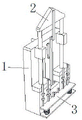
FIG. 1 is a schematic view of the overall structure of the present invention;
FIG. 2 is a schematic structural view of a base according to the present invention;
FIG. 3 is a schematic view of the structure of the lift pin of the present invention;
fig. 4 is a schematic structural view of the step plate of the present invention.
In the figure: 1. a base; 2. a top plate; 3. a pedal; 4. a working groove; 5. a rod groove; 6. a drive shaft; 7. a fixed block; 8. a chute; 9. stamping the blocks; 10. a circular groove; 11. a rectangular groove; 12. a limiting ring; 13. rotating the block; 14. a first rotating rod; 15. connecting blocks; 16. a second rotating rod; 17. a connecting rod; 18. briquetting; 19. a lifting rod; 20. a round block; 21. a third rotating rod; 22. a base plate; 23. a spring; 24. a stop lever; 25. and (4) inserting the rod.
Detailed Description
In order to make the objects, technical solutions and advantages of the present application more apparent, the technical solutions of the present application will be described in detail and completely with reference to the following specific embodiments of the present application and the accompanying drawings. It should be apparent that the described embodiments are only some of the embodiments of the present application, and not all of the embodiments. All other embodiments, which can be derived by a person skilled in the art from the embodiments given herein without making any creative effort, shall fall within the protection scope of the present application.
The technical solutions provided by the embodiments of the present application are described in detail below with reference to the accompanying drawings.
Referring to fig. 1-4, a rapid stamping and forming device for hardware comprises a base 1, a working groove 4 is formed at the upper end of the right surface of the base 1, two pairs of limiting rings 12 are fixedly connected to the front and rear sides of the lower end of the right surface of the base 1, a sliding groove 8 is penetrated through the middle part of the right surface of the base 1, a stamping block 9 capable of sliding up and down is movably arranged in the sliding groove 8, two fixing blocks 7 are fixedly connected to the upper end of the left groove surface of the working groove 4, rod grooves 5 are penetrated through the upper and lower surfaces of the two fixing blocks 7, a driving shaft 6 is arranged at the upper end of the left groove surface of the working groove 4, a lifting mechanism is arranged in the two rod grooves 5, the lifting mechanism comprises a top plate 2 and two lifting rods 19, a limiting mechanism is arranged in the limiting ring 12, the limiting mechanism comprises a pedal 3 and a bottom plate 22, a rectangular groove 11 is formed on the upper surface of the stamping block 9, a circular groove 10 is formed on the right surface of the stamping block 9, the circular groove 10 is communicated with the rectangular groove 11, the upper end of the right surface of the top plate 2 is rotatably connected with a rotating block 13, the upper ends of two lifting rods 19 are respectively and fixedly connected with the front end and the rear end of the lower surface of the top plate 2, and the lower ends of the two lifting rods 19 are respectively and fixedly connected with a pressing block 18;
a first rotating rod 14 is fixedly connected to the right end of the rotating block 13, a connecting block 15 is rotatably connected to the lower end of the first rotating rod 14, a second rotating rod 16 is fixedly connected to the left end of the connecting block 15, a connecting rod 17 is fixedly connected to the lower end of the second rotating rod 16, a round block 20 is rotatably connected to the middle portion of the left surface of the second rotating rod 16, a third rotating rod 21 is fixedly connected to the left end of the round block 20, the upper end of the third rotating rod 21 is fixedly connected to a driving shaft 6, the connecting rod 17 is movably sleeved with a round groove 10, the lower end of the connecting rod 17 is movably arranged in the rectangular groove 11, a pair of insertion rods 25 is fixedly connected to the front end and the rear end of the upper surface of the pedal 3, a pair of stop rods 24 is fixedly connected to the middle portion of the upper surface of the pedal 3, the driving shaft 6 drives the third rotating rod 21 to rotate, the second rotating rod 16 is driven by the round block 20 to swing, the first rotating rod 14 is driven by the connecting block 15 when the second rotating rod 16 swings, so that the top plate 2 moves up and down, the top plate 2 moves up and down to enable the two pressing blocks 18 to move up and down through the two lifting rods 19, the two pressing blocks 18 can press and fix two ends of a workpiece in the stamping process of the stamping block 9, the stability of the workpiece in the stamping process is improved, an operator enables the pedal 3 to move down by stepping on the pedal 3, the pedal 3 moves down to enable the upper end of the inserted rod 25 to be lower than the working groove 4, the workpiece can be taken and placed at the moment, the pedal 3 is loosened, when the pedal 3 rises under the action of the springs 23, the upper end of the inserted rod 25 exceeds the groove bottom of the working groove 4 to limit the workpiece in the left-right direction, the workpiece deviation in the stamping process is avoided, the stability is further improved, the two springs 23 are fixedly connected to the upper surface of the bottom plate 22, the upper ends of the two springs 23 are fixedly connected to the lower surface of the pedal 3, the two pairs of inserted rods 25 are respectively movably sleeved with the corresponding limiting rings 12, and the left end of the bottom plate 22 is fixedly connected with the base 1, the left surface of the pedal 3 is movably jointed with the right surface of the base 1.
When in use, the driving shaft 6 drives the third rotating rod 21 to rotate, the third rotating rod 21 rotates to drive the second rotating rod 16 to swing through the round block 20, the second rotating rod 16 drives the first rotating rod 14 to swing through the connecting block 15 when swinging, the top plate 2 is driven to move up and down, the top plate 2 moves up and down, the two pressing blocks 18 move up and down through the two lifting rods 19, two pressing blocks 18 can press and fix two ends of a workpiece in the stamping process of a stamping block 9, the stability of the workpiece in the stamping process is improved, an operator can move the pedal 3 downwards by stepping on the pedal 3, the pedal 3 moves downwards to enable the upper end of the inserted rod 25 to be lower than the working groove 4, the workpiece can be taken and placed at the moment, the pedal 3 is loosened, when the pedal 3 ascends under the action of the spring 23, the upper end of the inserted rod 25 exceeds the groove bottom of the working groove 4, the workpiece is limited in the left and right directions, so that the workpiece is prevented from being deviated during stamping, and the stability is further improved.
As will be appreciated by one skilled in the art, embodiments of the present invention may be provided as a method, system, or computer program product. Accordingly, the present invention may take the form of an entirely hardware embodiment, an entirely software embodiment or an embodiment combining software and hardware aspects. Furthermore, the present invention may take the form of a computer program product embodied on one or more computer-usable storage media having computer-usable program code embodied in the medium.
It should also be noted that the terms "comprises," "comprising," or any other variation thereof, are intended to cover a non-exclusive inclusion, such that a process, method, article, or apparatus that comprises a list of elements does not include only those elements but may include other elements not expressly listed or inherent to such process, method, article, or apparatus. Without further limitation, an element defined by the phrase "comprising an … …" does not exclude the presence of other like elements in a process, method, article, or apparatus that comprises the element.
The above description is only an example of the present application and is not intended to limit the present application. Various modifications and changes may occur to those skilled in the art. Any modification, equivalent replacement, improvement, etc. made within the spirit and principle of the present application should be included in the scope of the claims of the present application.
Claims (6)
1. The utility model provides a hardware rapid stamping forming device, includes base (1), its characterized in that: the upper end of the right surface of the base (1) is provided with a working groove (4), the front side and the rear side of the lower end of the right surface of the base (1) are fixedly connected with two pairs of limiting rings (12), the middle part of the right surface of the base (1) is penetrated with a sliding groove (8), a stamping block (9) which can only slide up and down is movably arranged in the sliding groove (8), the upper end of the left groove surface of the working groove (4) is fixedly connected with two fixed blocks (7), the upper surface and the lower surface of the two fixed blocks (7) are penetrated with a rod groove (5), and the upper end of the left groove surface of the working groove (4) is provided with a driving shaft (6);
lifting mechanisms are arranged in the two rod grooves (5), and each lifting mechanism comprises a top plate (2) and two lifting rods (19);
a limiting mechanism is arranged in the limiting ring (12) and comprises a pedal (3) and a bottom plate (22).
2. The rapid stamping and forming device for hardware as claimed in claim 1, wherein: rectangular channel (11) have been seted up to the upper surface of punching press piece (9), circular slot (10) have been seted up to the right surface of punching press piece (9), circular slot (10) and rectangular channel (11) switch-on.
3. The rapid stamping and forming device for hardware as claimed in claim 1, wherein: the upper end of the right surface of the top plate (2) is rotatably connected with a rotating block (13), the upper ends of the lifting rods (19) are fixedly connected with the front end and the rear end of the lower surface of the top plate (2) respectively, and the lower ends of the lifting rods (19) are fixedly connected with pressing blocks (18).
4. The rapid stamping and forming device for hardware as claimed in claim 3, wherein: the right-hand member fixedly connected with bull stick (14) of bull stick (13), the lower extreme of bull stick (14) is rotated and is connected with connecting block (15), the left end fixedly connected with bull stick two (16) of connecting block (15), the lower extreme fixedly connected with connecting rod (17) of bull stick two (16), the left surface mid portion of bull stick two (16) is rotated and is connected with circle piece (20), the left end fixedly connected with bull stick three (21) of circle piece (20), the upper end and drive shaft (6) fixed connection of bull stick three (21).
5. The rapid stamping and forming device for hardware as claimed in claim 4, wherein: the connecting rod (17) is movably sleeved with the circular groove (10), and the lower end of the connecting rod (17) is movably arranged in the rectangular groove (11).
6. The rapid stamping and forming device for hardware as claimed in claim 1, wherein: the utility model discloses a pair of footboard (3) upper surface's the equal fixedly connected with in both ends a pair of inserted bar (25) around footboard (3), the upper surface middle part fixedly connected with of footboard (3) a pair of pin (24), two springs (23) of the upper surface fixedly connected with of bottom plate (22), two the upper end of spring (23) all with the lower fixed surface of footboard (3) be connected, two pairs inserted bar (25) cup joint with the spacing ring (12) activity that corresponds respectively, bottom plate (22) left end and base (1) fixed connection, footboard (3) left surface and base (1) right side surface activity laminating.
Priority Applications (1)
| Application Number | Priority Date | Filing Date | Title |
|---|---|---|---|
| CN202122496882.3U CN216324413U (en) | 2021-10-18 | 2021-10-18 | Hardware rapid stamping forming device |
Applications Claiming Priority (1)
| Application Number | Priority Date | Filing Date | Title |
|---|---|---|---|
| CN202122496882.3U CN216324413U (en) | 2021-10-18 | 2021-10-18 | Hardware rapid stamping forming device |
Publications (1)
| Publication Number | Publication Date |
|---|---|
| CN216324413U true CN216324413U (en) | 2022-04-19 |
Family
ID=81177183
Family Applications (1)
| Application Number | Title | Priority Date | Filing Date |
|---|---|---|---|
| CN202122496882.3U Active CN216324413U (en) | 2021-10-18 | 2021-10-18 | Hardware rapid stamping forming device |
Country Status (1)
| Country | Link |
|---|---|
| CN (1) | CN216324413U (en) |
-
2021
- 2021-10-18 CN CN202122496882.3U patent/CN216324413U/en active Active
Similar Documents
| Publication | Publication Date | Title |
|---|---|---|
| CN204735593U (en) | Pressure manifold jack stamping device | |
| CN210702046U (en) | Stable stamping die for automobile chassis | |
| CN216324413U (en) | Hardware rapid stamping forming device | |
| CN216937977U (en) | Flanging stamping die structure | |
| CN111842693A (en) | Three-dimensional punching machine | |
| CN206898203U (en) | A kind of hub trimming die tool | |
| CN206716864U (en) | One kind can the easy positioning filter disc decompressor of letter | |
| CN213968638U (en) | Multifunctional metal plate stamping die | |
| CN214184814U (en) | Steel plate punch forming device for producing polyurethane cold storage plate | |
| CN113057358A (en) | Bean curd skin pushing and labeling device | |
| CN112719955A (en) | Workpiece clamping device of sawing machine and clamping method thereof | |
| CN211539113U (en) | Buffer device for punch press | |
| CN215207288U (en) | Plane automatic workpiece taking manipulator | |
| CN220574483U (en) | Metal plate punching device | |
| CN213469440U (en) | Fixed block processing forging press | |
| CN219259843U (en) | Servo stamping device of borosilicate glassware | |
| CN220259236U (en) | Continuous die punch | |
| CN111438277B (en) | Stamping die and stamping process thereof | |
| CN213079704U (en) | Circular tube arc cutting die and punching machine | |
| CN220784113U (en) | Positioning mechanism and rubber punching machine thereof | |
| CN218747285U (en) | Automatic key cap assembling machine | |
| CN220591246U (en) | Metal part stamping device | |
| CN214211972U (en) | A punch press for low-voltage cabinet body processing | |
| CN220390366U (en) | Rubber foot pressing device | |
| CN220697942U (en) | Elastic stamping mechanism for part machining |
Legal Events
| Date | Code | Title | Description |
|---|---|---|---|
| GR01 | Patent grant | ||
| GR01 | Patent grant |