CN216307116U - Digital media is hanging support for equipment with angle modulation function - Google Patents
Digital media is hanging support for equipment with angle modulation function Download PDFInfo
- Publication number
- CN216307116U CN216307116U CN202120081920.6U CN202120081920U CN216307116U CN 216307116 U CN216307116 U CN 216307116U CN 202120081920 U CN202120081920 U CN 202120081920U CN 216307116 U CN216307116 U CN 216307116U
- Authority
- CN
- China
- Prior art keywords
- block
- rod
- movable
- digital media
- limiting
- Prior art date
- Legal status (The legal status is an assumption and is not a legal conclusion. Google has not performed a legal analysis and makes no representation as to the accuracy of the status listed.)
- Expired - Fee Related
Links
Images


Landscapes
- Devices For Indicating Variable Information By Combining Individual Elements (AREA)
Abstract
本实用新型属于数字媒体产设备技术领域,尤其为一种具有角度调节功能的数字媒体设备用悬挂支架,包括支撑台和固定块,所述支撑台的底部连接有支撑柱,且支撑柱的底部安装有固定板,并且支撑台的内部安装有连接杆,所述连接杆的外侧设置有滑块,且滑块的底部右侧连接有限位块,并且限位块的右侧设置有活动杆,所述滑块的顶部连接有旋转轴,且旋转轴的顶部安装有支撑杆,并且支撑杆的顶部设置有连接轴。该具有角度调节功能的数字媒体设备用悬挂支架,滑块与限位块之间为紧密贴合,且限位块与活动杆之间为焊接连接,且活动杆与支撑台之间为螺纹连接,通过转动活动杆使限位块进行移动,带动滑块进行位移,便于调节限位框的角度。
The utility model belongs to the technical field of digital media production equipment, in particular to a suspension bracket for digital media equipment with an angle adjustment function, comprising a support table and a fixing block, the bottom of the support table is connected with a support column, and the bottom of the support column is A fixing plate is installed, and a connecting rod is installed inside the support table, a slider is arranged on the outer side of the connecting rod, and a limit block is connected to the bottom right side of the slider, and a movable rod is arranged on the right side of the limit block, A rotating shaft is connected to the top of the sliding block, a supporting rod is installed on the top of the rotating shaft, and a connecting shaft is disposed on the top of the supporting rod. In the suspension bracket for digital media equipment with angle adjustment function, the sliding block and the limit block are closely fitted, and the limit block and the movable rod are welded and connected, and the movable rod and the support table are threadedly connected , The limit block is moved by rotating the movable rod, and the slider is driven to move, which is convenient to adjust the angle of the limit frame.
Description
技术领域technical field
本实用新型涉及数字媒体设备技术领域,具体为一种具有角度调节功能的数字媒体设备用悬挂支架。The utility model relates to the technical field of digital media equipment, in particular to a suspension bracket for digital media equipment with an angle adjustment function.
背景技术Background technique
在多媒体教学办公时代,交互式一体机、电视等多媒体设备已经被普及应用。安装使用时,交互式一体机、电视等多媒体设备一般是通过壁挂架悬挂在墙壁上。In the era of multimedia teaching and office, multimedia equipment such as interactive all-in-one computers and TVs have been widely used. During installation and use, multimedia equipment such as interactive all-in-one machines and TVs are generally hung on the wall through wall mounts.
目前数字媒体设备用悬挂支架已成为比较成熟的使用工具,但是一般数字媒体设备用悬挂支架在工作时,不能根据现场情况进行高度调节,不具有升降结构,不便于使用,且不便于多角度使用,不便于调节角度。At present, the suspension bracket for digital media equipment has become a relatively mature tool. However, when the suspension bracket for general digital media equipment is working, the height cannot be adjusted according to the site conditions. , it is not easy to adjust the angle.
综上所述,现有的数字媒体设备用悬挂支架在工作时,不能根据现场情况进行高度调节,不具有升降结构,不便于使用,不便于调节角度的缺点。针对上述问题,急需在原有悬挂支架的基础上进行创新设计。To sum up, the existing suspension brackets for digital media equipment cannot be height-adjusted according to site conditions during operation, have no lifting structure, are inconvenient to use, and are inconvenient to adjust the angle. In view of the above problems, it is urgent to carry out innovative design on the basis of the original suspension bracket.
实用新型内容Utility model content
本实用新型的目的在于提供一种具有角度调节功能的数字媒体设备用悬挂支架,以解决上述背景技术中提出不能根据现场情况进行高度调节,不具有升降结构,不便于使用,不便于调节角度的问题。The purpose of the present utility model is to provide a suspension bracket for digital media equipment with an angle adjustment function, so as to solve the problem that the height adjustment cannot be carried out according to the on-site situation in the above-mentioned background art, and it does not have a lifting structure, which is inconvenient to use and inconvenient to adjust the angle. question.
为实现上述目的,本实用新型提供如下技术方案:一种具有角度调节功能的数字媒体设备用悬挂支架,包括支撑台和固定块,所述支撑台的底部连接有支撑柱,且支撑柱的底部安装有固定板,并且支撑台的内部安装有连接杆,所述连接杆的外侧设置有滑块,且滑块的底部右侧连接有限位块,并且限位块的右侧设置有活动杆,所述滑块的顶部连接有旋转轴,且旋转轴的顶部安装有支撑杆,并且支撑杆的顶部设置有连接轴,同时连接轴的外侧安装有连接块,所述固定块设置于支撑台的顶部左侧,且固定块的顶部连接有活动轴,并且活动轴的顶部安装有限位框,所述限位框的内部设置有滑杆,且滑杆的外侧安装有活动块,并且活动块的顶部设置有限位板,所述限位板的外侧连接有弹力杆。In order to achieve the above purpose, the present invention provides the following technical solutions: a suspension bracket for digital media equipment with an angle adjustment function, comprising a support table and a fixing block, the bottom of the support table is connected with a support column, and the bottom of the support column is A fixed plate is installed, and a connecting rod is installed inside the support table, a slider is arranged on the outer side of the connecting rod, and a limit block is connected to the bottom right side of the slider, and a movable rod is arranged on the right side of the limit block, The top of the slider is connected with a rotating shaft, and a support rod is installed on the top of the rotating shaft, and the top of the support rod is provided with a connecting shaft, and a connecting block is installed on the outside of the connecting shaft, and the fixing block is installed on the support table. The left side of the top, and a movable shaft is connected to the top of the fixed block, and a limit frame is installed on the top of the movable shaft, the inside of the limit frame is provided with a sliding rod, and the outer side of the sliding rod A limit plate is arranged on the top, and an elastic rod is connected to the outer side of the limit plate.
优选的,所述支撑台与连接杆为卡合连接,且连接杆与滑块之间为滑动连接。Preferably, the support platform and the connecting rod are in a snap connection, and the connecting rod and the slider are in a sliding connection.
优选的,所述滑块与限位块之间为紧密贴合,且限位块与活动杆之间为焊接连接,且活动杆与支撑台之间为螺纹连接。Preferably, the sliding block and the limit block are in close contact, the limit block and the movable rod are connected by welding, and the movable rod and the support table are connected by a thread.
优选的,所述支撑杆与连接块之间通过连接轴构成转动结构,且连接块与限位框之间为焊接连接。Preferably, a rotating structure is formed between the support rod and the connecting block through a connecting shaft, and the connecting block and the limiting frame are connected by welding.
优选的,所述固定块与限位框之间通过活动轴构成转动结构,且限位框与限位板之间为滑动连接。Preferably, a rotating structure is formed between the fixed block and the limit frame through a movable shaft, and the limit frame and the limit plate are in a sliding connection.
优选的,所述滑杆与活动块之间为滑动连接,且活动块与限位板之间为卡合连接。Preferably, the sliding rod and the movable block are in a sliding connection, and the movable block and the limiting plate are in a snap connection.
优选的,所述限位板关于限位框的中轴线对称设置,且限位板与弹力杆之间为粘接连接。Preferably, the limit plate is symmetrically arranged with respect to the central axis of the limit frame, and the limit plate and the elastic rod are in an adhesive connection.
与现有技术相比,本实用新型的有益效果是:Compared with the prior art, the beneficial effects of the present utility model are:
1、该具有角度调节功能的数字媒体设备用悬挂支架,滑块与限位块之间为紧密贴合,且限位块与活动杆之间为焊接连接,且活动杆与支撑台之间为螺纹连接,通过转动活动杆使限位块进行移动,带动滑块进行位移,便于调节限位框的角度;1. The suspension bracket for digital media equipment with the function of angle adjustment, the slider and the limit block are closely fitted, and the limit block and the movable rod are welded and connected, and the movable rod and the support table are connected by welding. Threaded connection, the limit block is moved by rotating the movable rod, and the slider is driven to move, which is convenient to adjust the angle of the limit frame;
2、该具有角度调节功能的数字媒体设备用悬挂支架,固定块与限位框之间通过活动轴构成转动结构,且限位框与限位板之间为滑动连接,通过活动轴转动,使限位框角度调节,通过限位板在限位框的内部滑动,便于对设备进行限位固定;2. In the suspension bracket for digital media equipment with angle adjustment function, a rotating structure is formed between the fixed block and the limit frame through a movable shaft, and the limit frame and the limit plate are slidingly connected. The angle of the limit frame is adjusted, and the limit plate slides inside the limit frame, which is convenient to limit and fix the equipment;
3、该具有角度调节功能的数字媒体设备用悬挂支架,滑杆与活动块之间为滑动连接,且活动块与限位板之间为卡合连接,通过活动块在滑杆的表面滑动,可以移动限位板的位置,便于根据不同大小的设备进行固定限位。3. The suspension bracket for digital media equipment with the function of angle adjustment has a sliding connection between the sliding rod and the movable block, and a snap connection between the movable block and the limit plate, and slides on the surface of the sliding rod through the movable block. The position of the limit plate can be moved, which is convenient for fixing the limit according to different sizes of equipment.
附图说明Description of drawings
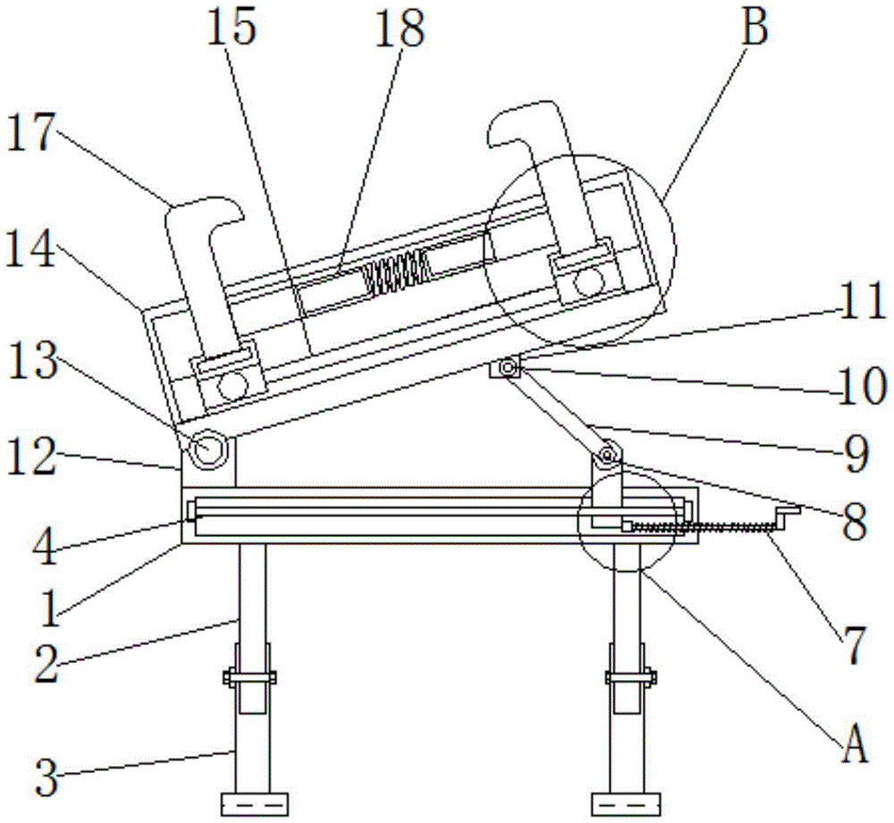
图1为本实用新型正视剖面结构示意图;Fig. 1 is the front view sectional structure schematic diagram of the utility model;
图2为本实用新型正视结构示意图;Fig. 2 is the front view structure schematic diagram of the utility model;
图3为本实用新型图1中A处放大结构示意图;Fig. 3 is the enlarged structural schematic diagram at A in Fig. 1 of the utility model;
图4为本实用新型图1中B处放大结构示意图。FIG. 4 is an enlarged schematic view of the structure at B in FIG. 1 of the present utility model.
图中:1、支撑台;2、支撑柱;3、固定板;4、连接杆;5、滑块;6、限位块;7、活动杆;8、旋转轴;9、支撑杆;10、连接轴;11、连接块;12、固定块;13、活动轴;14、限位框;15、滑杆;16、活动块;17、限位板;18、弹力杆。In the figure: 1, support table; 2, support column; 3, fixed plate; 4, connecting rod; 5, slider; 6, limit block; 7, movable rod; 8, rotating shaft; 9, support rod; 10 , connecting shaft; 11, connecting block; 12, fixed block; 13, movable shaft; 14, limit frame; 15, slide bar; 16, movable block; 17, limit plate; 18, elastic rod.
具体实施方式Detailed ways
下面将结合本实用新型实施例中的附图,对本实用新型实施例中的技术方案进行清楚、完整地描述,显然,所描述的实施例仅仅是本实用新型一部分实施例,而不是全部的实施例。基于本实用新型中的实施例,本领域普通技术人员在没有做出创造性劳动前提下所获得的所有其他实施例,都属于本实用新型保护的范围。The technical solutions in the embodiments of the present utility model will be clearly and completely described below with reference to the accompanying drawings in the embodiments of the present utility model. Obviously, the described embodiments are only a part of the embodiments of the present utility model, rather than all the implementations. example. Based on the embodiments of the present invention, all other embodiments obtained by those of ordinary skill in the art without creative work fall within the protection scope of the present invention.
请参阅图1-4,本实用新型提供一种技术方案:一种具有角度调节功能的数字媒体设备用悬挂支架,包括支撑台1、支撑柱2、固定板3、连接杆4、滑块5、限位块6、活动杆7、旋转轴8、支撑杆9、连接轴10、连接块11、固定块12、活动轴13、限位框14、滑杆15、活动块16、限位板17和弹力杆18,支撑台1的底部连接有支撑柱2,且支撑柱2的底部安装有固定板3,并且支撑台1的内部安装有连接杆4,连接杆4的外侧设置有滑块5,且滑块5的底部右侧连接有限位块6,并且限位块6的右侧设置有活动杆7,滑块5的顶部连接有旋转轴8,且旋转轴8的顶部安装有支撑杆9,并且支撑杆9的顶部设置有连接轴10,同时连接轴10的外侧安装有连接块11,固定块12设置于支撑台1的顶部左侧,且固定块12的顶部连接有活动轴13,并且活动轴13的顶部安装有限位框14,限位框14的内部设置有滑杆15,且滑杆15的外侧安装有活动块16,并且活动块16的顶部设置有限位板17,限位板17的外侧连接有弹力杆18。1-4, the present utility model provides a technical solution: a suspension bracket for digital media equipment with an angle adjustment function, comprising a support table 1, a
本实施例中,支撑台1与连接杆4为卡合连接,且连接杆4与滑块5之间为滑动连接,通过滑块5在连接杆4的表面滑动,可以调节限位框14的放置角度,便于使用。In this embodiment, the support table 1 and the connecting
本实施例中,滑块5与限位块6之间为紧密贴合,且限位块6与活动杆7之间为焊接连接,且活动杆7与支撑台1之间为螺纹连接,通过转动活动杆7使限位块6进行移动,带动滑块5进行位移,便于调节限位框14的角度。In this embodiment, the
本实施例中,支撑杆9与连接块11之间通过连接轴10构成转动结构,且连接块11与限位框14之间为焊接连接,通过连接轴10转动,使支撑杆9的倾斜角度变化,导致限位框14进行角度调节。In this embodiment, the connecting
本实施例中,固定块12与限位框14之间通过活动轴13构成转动结构,且限位框14与限位板17之间为滑动连接,通过活动轴13转动,使限位框14角度调节,通过限位板17在限位框14的内部滑动,便于对设备进行限位固定。In this embodiment, a rotating structure is formed between the
本实施例中,滑杆15与活动块16之间为滑动连接,且活动块16与限位板17之间为卡合连接,通过活动块16在滑杆15的表面滑动,可以移动限位板17的位置,便于根据不同大小的设备进行固定限位。In this embodiment, the
本实施例中,限位板17关于限位框14的中轴线对称设置,且限位板17与弹力杆18之间为粘接连接,通过限位板17对设备进行限位,通过弹力杆18对限位板17进行限位固定,便于固定设备。In this embodiment, the
工作原理:该具有角度调节功能的数字媒体设备用悬挂支架使用流程为,首先将固定板3固定在墙壁上,通过支撑柱2在固定板3的内部进行滑动,且通过螺杆进行固定,便于调节设备使用的高度;Working principle: The use process of the suspension bracket for digital media equipment with angle adjustment function is to first fix the
通过活动块16在滑杆15的表面滑动,可以移动限位板17的位置,便于根据不同大小的设备进行固定限位,通过限位板17对设备进行限位,通过弹力杆18对限位板17进行限位固定,便于固定设备;By sliding the
通过转动活动杆7使限位块6进行移动,带动滑块5进行位移,通过滑块5在连接杆4的表面滑动,使连接轴10和旋转轴8发生转动,使支撑杆9的倾斜角度变化,通过活动轴13转动,便于限位框14进行角度调节。By rotating the
尽管已经示出和描述了本实用新型的实施例,对于本领域的普通技术人员而言,可以理解在不脱离本实用新型的原理和精神的情况下可以对这些实施例进行多种变化、修改、替换和变型,本实用新型的范围由所附权利要求及其等同物限定。Although the embodiments of the present invention have been shown and described, it will be understood by those skilled in the art that various changes and modifications can be made to these embodiments without departing from the principles and spirit of the present invention , alternatives and modifications, the scope of the present invention is defined by the appended claims and their equivalents.
Claims (7)
Priority Applications (1)
| Application Number | Priority Date | Filing Date | Title |
|---|---|---|---|
| CN202120081920.6U CN216307116U (en) | 2021-01-06 | 2021-01-06 | Digital media is hanging support for equipment with angle modulation function |
Applications Claiming Priority (1)
| Application Number | Priority Date | Filing Date | Title |
|---|---|---|---|
| CN202120081920.6U CN216307116U (en) | 2021-01-06 | 2021-01-06 | Digital media is hanging support for equipment with angle modulation function |
Publications (1)
| Publication Number | Publication Date |
|---|---|
| CN216307116U true CN216307116U (en) | 2022-04-15 |
Family
ID=81081508
Family Applications (1)
| Application Number | Title | Priority Date | Filing Date |
|---|---|---|---|
| CN202120081920.6U Expired - Fee Related CN216307116U (en) | 2021-01-06 | 2021-01-06 | Digital media is hanging support for equipment with angle modulation function |
Country Status (1)
| Country | Link |
|---|---|
| CN (1) | CN216307116U (en) |
-
2021
- 2021-01-06 CN CN202120081920.6U patent/CN216307116U/en not_active Expired - Fee Related
Similar Documents
| Publication | Publication Date | Title |
|---|---|---|
| CN206722447U (en) | A kind of building support for construction positioner | |
| CN216307116U (en) | Digital media is hanging support for equipment with angle modulation function | |
| CN208077011U (en) | A kind of console that can be interactive | |
| CN209256732U (en) | A PCBA maintenance bracket jig | |
| CN217765027U (en) | A spatial position adjustment device for photoelectric detection equipment | |
| CN218523314U (en) | A column display stand | |
| CN211984334U (en) | Combined office table | |
| CN210979268U (en) | A TV with multi-angle rotation function | |
| CN221922977U (en) | Office supplies desktop support | |
| CN210662145U (en) | Adjustable desktop computer support frame | |
| CN213629692U (en) | Three-dimensional laser scanner support with accurate locate function for pipeline design | |
| CN209128897U (en) | A kind of bridge Construction Support device | |
| CN208950341U (en) | A kind of very poor control tool of window abutment wall concentric reducer thickness | |
| CN210428979U (en) | A demonstration stand for accounting teaching that is easy to adjust the angle | |
| CN206938323U (en) | A kind of new art easel | |
| CN216009773U (en) | Anti-seismic fine-adjustment positioning device for adjusting angle of drainage pipe network | |
| CN216434421U (en) | A kind of coating equipment for double-sided composite lens | |
| CN217618656U (en) | Multi-functional rotation type welding frock of display support arm | |
| CN206124607U (en) | Oil drawing board mount | |
| CN222748227U (en) | Vibration detection clamp for display screen | |
| CN218236784U (en) | Display screen support convenient to adjust and move | |
| CN211956995U (en) | Angle-adjustable spliced screen | |
| CN216265589U (en) | Clamping device convenient for hydraulic machinery | |
| CN221974822U (en) | Angle adjustment structure of multimedia projection equipment | |
| CN216440135U (en) | Detachable filter core support with bilayer structure |
Legal Events
| Date | Code | Title | Description |
|---|---|---|---|
| GR01 | Patent grant | ||
| GR01 | Patent grant | ||
| TR01 | Transfer of patent right |
Effective date of registration: 20230803 Address after: 4th Floor, Building 9, No. 260 Ganggang North Road, Xindu District, Xingtai City, Hebei Province, 054000 Patentee after: Xinyi Longquan Media Studio in Xindu District Address before: 054000 No. 552, North Steel Road, Hebei, Xingtai Patentee before: XINGTAI POLYTECHNIC College |
|
| TR01 | Transfer of patent right | ||
| CF01 | Termination of patent right due to non-payment of annual fee |
Granted publication date: 20220415 |
|
| CF01 | Termination of patent right due to non-payment of annual fee |