CN216297790U - Safety protection structure is used in punching machine processing - Google Patents
Safety protection structure is used in punching machine processing Download PDFInfo
- Publication number
- CN216297790U CN216297790U CN202122677221.0U CN202122677221U CN216297790U CN 216297790 U CN216297790 U CN 216297790U CN 202122677221 U CN202122677221 U CN 202122677221U CN 216297790 U CN216297790 U CN 216297790U
- Authority
- CN
- China
- Prior art keywords
- fixedly connected
- movable
- groove
- rod
- punching machine
- Prior art date
- Legal status (The legal status is an assumption and is not a legal conclusion. Google has not performed a legal analysis and makes no representation as to the accuracy of the status listed.)
- Active
Links
Images


Abstract
The utility model relates to the field of punching machines, in particular to a safety protection structure for punching machine machining. According to the safety protection structure, the motor is started to drive the screw rod to rotate, the threaded pipe is driven to move up and down through the rotation of the screw rod, and the threaded pipe drives the slide rod and the movable frame to move up and down, so that the safety protection structure can be conveniently adjusted by people, people can conveniently replace finished products processed by the punching machine by moving the movable frame, the work requirements of people are met, and the work efficiency of the safety protection structure is improved.
Description
Technical Field
The utility model relates to the technical field of punching machines, in particular to a safety protection structure for punching machine machining.
Background
The punch press is a stamping type press. In national production, the stamping process has the advantages of material and energy conservation, high efficiency, low technical requirement on operators and capability of manufacturing products which cannot be achieved by mechanical processing through various die applications compared with the traditional mechanical processing, so that the stamping process has more and more extensive applications, and a protective structure is required to be used for protection when a stamping machine is used for processing, thereby avoiding the harm to people caused by the occurrence of conditions.
However, the existing safety protection structure is not convenient to adjust, so that people can not conveniently place and take processed products by adjusting the installation protection structure, the work efficiency of people is affected, the work requirement of people is not met, the work efficiency of the safety protection structure is reduced, and the work of people is inconvenient.
Therefore, a safety protection structure for punching processing is needed.
SUMMERY OF THE UTILITY MODEL
In order to solve the problem that the safety protection structure is inconvenient to adjust, the utility model aims to provide the safety protection structure for the machining of the punching machine.
The safety protection structure for machining of the punching machine comprises a workbench, wherein the bottom of the workbench is fixedly connected with supporting legs, the top of the workbench is fixedly connected with a punching machine body, the top of the workbench is fixedly connected with a side plate, the top of the side plate is fixedly connected with a top plate, one side of the side plate is fixedly connected with a fixing frame, the inner side wall of the side plate is fixedly connected with a baffle, the bottom of the baffle is fixedly connected with a motor, and an output shaft of the motor is fixedly connected with a screw rod through a coupler.
The one end fixedly connected with fixed block of screw rod, the outer wall swing joint of screw rod has the screwed pipe, the outer wall fixedly connected with slide bar of screwed pipe, the one end fixedly connected with movable frame of slide bar, one side fixedly connected with movable rod of movable frame, the one end fixedly connected with slider of movable rod.
Preferably, a first glass groove is formed in the front face of the fixing frame, first toughened glass is fixedly connected to the inner wall of the first glass groove, and the work of the punching machine is conveniently observed through the first toughened glass.
Preferably, the front surface of the movable frame is provided with a second glass groove, the inner wall of the second glass groove is fixedly connected with second toughened glass, and the working process of the punching machine is conveniently observed through the second toughened glass.
Preferably, the bottom of the baffle is provided with a through hole, the screw rod is movably connected with the baffle through the through hole, and the screw rod is convenient to move through the through hole.
Preferably, a sliding groove is formed in one side of the side plate, the sliding rod is movably connected with the side plate through the sliding groove, and the sliding rod can move conveniently through the sliding groove.
Preferably, one side of the fixed frame is provided with a groove, the sliding block is movably connected with the fixed frame through the groove, and the sliding block is convenient to move through the groove.
Preferably, a movable groove is formed in one side of the fixed frame, the movable rod is movably connected with the fixed frame through the movable groove, and the movable rod can move conveniently through the movable groove.
Preferably, the movable frame is movably connected with the side plate through a sliding rod, the movable frame is movably connected with the fixed frame through a movable rod, and the movable frame is convenient to move through the sliding rod and the movable rod.
The working principle is as follows: when the punching machine is operated and used, raw materials are placed in the punching machine body, the motor is started to drive the screw rod to rotate, the threaded pipe is driven to move up and down through the rotation of the screw rod, the threaded pipe drives the sliding rod and the movable frame to move up and down, the movable frame slides on one side of the fixed frame through the movable rod and the sliding block, the movable frame descends to contact with the workbench, the punching machine body works, the work of the punching machine is observed through the first toughened glass and the second toughened glass, the protection effect is achieved while the working process is observed, after the punching machine works, the motor is started, the screw rod rotates to drive the movable frame to move up, and people can conveniently replace processed finished products.
The technical means of the utility model can obtain the following technical effects:
(1) according to the safety protection structure, the motor is started, the screw rod is driven to rotate, the threaded pipe is driven to move up and down through the rotation of the screw rod, the threaded pipe drives the slide rod and the movable frame to move up and down, so that the safety protection structure can be convenient for people to adjust, people can conveniently replace finished products processed by the punching machine by moving the movable frame, the work requirements of people are met, and the work efficiency of the safety protection structure is improved.
(2) According to the safety protection structure, the fixed frame, the movable frame, the first toughened glass and the second toughened glass are arranged, so that people can conveniently observe the work of the punching machine, when the work goes wrong, the work pressure of people is relieved by finding at the first time, the work requirements of people are met, the work efficiency of the safety protection structure is improved, and convenience is brought to the work of people.
Drawings
FIG. 1 is a cross-sectional view of a safety shield structure of the present invention;
FIG. 2 is a front view of the safety shield structure of the present invention;
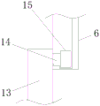
FIG. 3 is a schematic view of a connection structure of a side plate and a movable frame according to the present invention;
FIG. 4 is a top view of the fixed and movable frames of the present invention;
fig. 5 is a schematic view of a connection structure of the fixed frame and the movable frame according to the present invention.
In the figure: 1. a work table; 2. supporting legs; 3. a punch body; 4. a side plate; 5. a top plate; 6. a fixing frame; 7. a baffle plate; 8. a motor; 9. a screw; 10. a fixed block; 11. a threaded pipe; 12. a slide bar; 13. a movable frame; 14. a movable rod; 15. a slider; 16. first tempered glass; 17. and (7) second tempered glass.
Detailed Description
In order to more clearly understand the technical features, objects, and effects of the present invention, embodiments of the present invention will now be described with reference to the accompanying drawings.
Example 1
The preferred embodiment of the safety protection structure for stamping machine provided by the utility model is shown in fig. 1 to 5: the utility model provides a safety protection structure is used in punching machine processing, including workstation 1, the bottom fixedly connected with supporting leg 2 of workstation 1, the top fixedly connected with punching machine body 3 of workstation 1, the top fixedly connected with curb plate 4 of workstation 1, the top fixedly connected with roof 5 of curb plate 4, the fixed frame 6 of one side fixedly connected with of curb plate 4, the inside wall fixedly connected with baffle 7 of curb plate 4, the bottom fixedly connected with motor 8 of baffle 7, shaft coupling fixedly connected with screw rod 9 is passed through to motor 8's output shaft.
One end fixedly connected with fixed block 10 of screw rod 9, the outer wall swing joint of screw rod 9 has screwed pipe 11, the outer wall fixedly connected with slide bar 12 of screwed pipe 11, the one end fixedly connected with movable frame 13 of slide bar 12, one side fixedly connected with movable rod 14 of movable frame 13, through the fixed frame 6 that sets up, movable frame 13, first toughened glass 16 and second toughened glass 17, make this safety protection structure can make things convenient for people to observe the work of punching machine, can when the work goes wrong, the very first time discovery has lightened people's operating pressure, people's work demand has been satisfied, the work efficiency of this safety protection structure has been improved, the work of giving people has brought conveniently, the one end fixedly connected with slider 15 of movable rod 14, through the curb plate 4 that sets up, roof 5, fixed frame 6, baffle 7, motor 8, screw rod 9, screwed pipe 11, slide bar 12, Movable frame 13, movable rod 14 and slider 15, start through motor 8, drive screw rod 9 and rotate, it reciprocates to rotate drive screwed pipe 11 through screw rod 9, screwed pipe 11 drives slide bar 12 and movable frame 13 and reciprocates, make this safety protection structure can make things convenient for people to adjust, thereby make things convenient for people to remove through moving movable frame 13, change the finished product of punching machine processing, people's work demand has been satisfied, the work efficiency of this safety protection structure has been improved.
Example 2
On the basis of embodiment 1, a preferred embodiment of the safety protection structure for press working according to the present invention is shown in fig. 1 to 5: the front of the fixing frame 6 is provided with a first glass groove, the inner wall of the first glass groove is fixedly connected with a first toughened glass 16, and the work of the punching machine is conveniently observed through the first toughened glass 16.
In this embodiment, the second glass groove has been seted up on the front of movable frame 13, and the inner wall fixedly connected with second toughened glass 17 in second glass groove, conveniently observes the working process of punching machine through second toughened glass 17.
In this embodiment, the bottom of baffle 7 has seted up the through-hole, and screw rod 9 passes through-hole and baffle 7 swing joint, makes things convenient for screw rod 9 to move about through the through-hole.
In this embodiment, a sliding groove is formed in one side of the side plate 4, and the sliding rod 12 is movably connected with the side plate 4 through the sliding groove, so that the sliding rod 12 can move conveniently through the sliding groove.
In this embodiment, the recess has been seted up to one side of fixed frame 6, and slider 15 makes things convenient for slider 15 to move about through recess and fixed frame 6 swing joint through the recess.
In this embodiment, a movable groove is opened at one side of the fixed frame 6, and the movable rod 14 is movably connected with the fixed frame 6 through the movable groove, so that the movable rod 14 can move conveniently through the movable groove.
In this embodiment, the movable frame 13 is movably connected to the side plate 4 through the sliding rod 12, and the movable frame 13 is movably connected to the fixed frame 6 through the movable rod 14, so that the movable frame 13 can move conveniently through the sliding rod 12 and the movable rod 14.
When the punching machine is operated and used, as shown in figures 1 to 5, raw materials are placed in the punching machine body 3, the motor 8 is started to drive the screw rod 9 to rotate, the screw rod 9 rotates to drive the threaded pipe 11 to move up and down, the threaded pipe 11 drives the sliding rod 12 and the movable frame 13 to move up and down, the movable frame 13 slides on one side of the fixed frame 6 through the movable rod 14 and the sliding block 15, the movable frame 13 descends to contact the workbench 1, the punching machine body 3 works, the work of the punching machine is observed through the first toughened glass 16 and the second toughened glass 17, the punching machine plays a role in protection while the working process is observed, after the punching machine works, the motor 8 is started, the screw rod 9 rotates to drive the movable frame 13 to move up, and people can conveniently replace processed finished products.
The above description is only an exemplary embodiment of the present invention, and is not intended to limit the scope of the present invention. Any equivalent changes and modifications that can be made by one skilled in the art without departing from the spirit and principles of the utility model should be considered within the scope of the utility model. Moreover, it should be noted that the components of the present invention are not limited to the above-mentioned whole application, and various technical features described in the present specification can be selected to be used alone or in combination according to actual needs, so that the present invention should cover other combinations and specific applications related to the present invention.
Claims (8)
1. The utility model provides a safety protection structure is used in punching machine processing, includes workstation (1), its characterized in that: the bottom of the workbench (1) is fixedly connected with a supporting leg (2), the top of the workbench (1) is fixedly connected with a punching machine body (3), the top of the workbench (1) is fixedly connected with a side plate (4), the top of the side plate (4) is fixedly connected with a top plate (5), one side of the side plate (4) is fixedly connected with a fixed frame (6), the inner side wall of the side plate (4) is fixedly connected with a baffle (7), the bottom of the baffle (7) is fixedly connected with a motor (8), and an output shaft of the motor (8) is fixedly connected with a screw (9) through a coupler;
the one end fixedly connected with fixed block (10) of screw rod (9), the outer wall swing joint of screw rod (9) has screwed pipe (11), the outer wall fixedly connected with slide bar (12) of screwed pipe (11), the one end fixedly connected with movable frame (13) of slide bar (12), one side fixedly connected with movable rod (14) of movable frame (13), the one end fixedly connected with slider (15) of movable rod (14).
2. The safety shield structure for press working of claim 1, wherein: the front surface of the fixing frame (6) is provided with a first glass groove, and the inner wall of the first glass groove is fixedly connected with first toughened glass (16).
3. The safety shield structure for press working of claim 1, wherein: and a second glass groove is formed in the front surface of the movable frame (13), and the inner wall of the second glass groove is fixedly connected with second toughened glass (17).
4. The safety shield structure for press working of claim 1, wherein: the bottom of the baffle (7) is provided with a through hole, and the screw rod (9) is movably connected with the baffle (7) through the through hole.
5. The safety shield structure for press working of claim 1, wherein: a sliding groove is formed in one side of the side plate (4), and the sliding rod (12) is movably connected with the side plate (4) through the sliding groove.
6. The safety shield structure for press working of claim 1, wherein: one side of the fixed frame (6) is provided with a groove, and the sliding block (15) is movably connected with the fixed frame (6) through the groove.
7. The safety shield structure for press working of claim 1, wherein: a movable groove is formed in one side of the fixed frame (6), and the movable rod (14) is movably connected with the fixed frame (6) through the movable groove.
8. The safety shield structure for press working of claim 1, wherein: the movable frame (13) is movably connected with the side plate (4) through a sliding rod (12), and the movable frame (13) is movably connected with the fixed frame (6) through a movable rod (14).
Priority Applications (1)
| Application Number | Priority Date | Filing Date | Title |
|---|---|---|---|
| CN202122677221.0U CN216297790U (en) | 2021-11-03 | 2021-11-03 | Safety protection structure is used in punching machine processing |
Applications Claiming Priority (1)
| Application Number | Priority Date | Filing Date | Title |
|---|---|---|---|
| CN202122677221.0U CN216297790U (en) | 2021-11-03 | 2021-11-03 | Safety protection structure is used in punching machine processing |
Publications (1)
| Publication Number | Publication Date |
|---|---|
| CN216297790U true CN216297790U (en) | 2022-04-15 |
Family
ID=81119045
Family Applications (1)
| Application Number | Title | Priority Date | Filing Date |
|---|---|---|---|
| CN202122677221.0U Active CN216297790U (en) | 2021-11-03 | 2021-11-03 | Safety protection structure is used in punching machine processing |
Country Status (1)
| Country | Link |
|---|---|
| CN (1) | CN216297790U (en) |
-
2021
- 2021-11-03 CN CN202122677221.0U patent/CN216297790U/en active Active
Similar Documents
| Publication | Publication Date | Title |
|---|---|---|
| CN207823841U (en) | A kind of safety-type forging press of auto parts machinery processing | |
| CN211218233U (en) | Stable in structure's pressure punch press for steel drum | |
| CN210498437U (en) | Water-cooling bench drilling machine capable of conveniently disassembling and assembling workpieces | |
| CN216297790U (en) | Safety protection structure is used in punching machine processing | |
| CN113426889A (en) | Mobile phone steel sheet stamping device convenient to clearance waste material | |
| CN106553240B (en) | Woodworking rotary coaxial double-arm profiling edge milling machine | |
| CN109622852B (en) | Open type double-point press | |
| CN211464445U (en) | Special press in duplex position | |
| CN216027704U (en) | Closed door type double-crankshaft precision punch with overload protection | |
| CN215824068U (en) | Special die for water heater motor support | |
| CN215786221U (en) | Open type double-crankshaft precision overhead punch press | |
| CN210754712U (en) | Punching die for producing disc type scaffold pressing block | |
| CN213650051U (en) | Bag taking structure for packaging bag | |
| CN111842684B (en) | Workpiece fixing mechanism for hydraulic punching machine | |
| CN210936764U (en) | Servo motor stator and rotor punching sheet processing device | |
| CN210730657U (en) | Engine high-performance cooling wear-resistant chip cushion block open type fixed table press | |
| CN205097574U (en) | Energy -conserving closed high accuracy one point press | |
| CN110744600A (en) | Automatic cutting device for producing rubber sealing element | |
| CN211386590U (en) | Metal product stamping platform | |
| CN215614332U (en) | Punching machine convenient to adjust processing part position | |
| CN212704074U (en) | Perforating punch press is used in pipe fitting work piece production | |
| CN220532657U (en) | Pneumatic shaping and pressing equipment | |
| CN217191939U (en) | Press machine | |
| CN213004064U (en) | Cutting device for die machining | |
| CN218775768U (en) | Plate shearing machine is used in steel construction panel processing |
Legal Events
| Date | Code | Title | Description |
|---|---|---|---|
| GR01 | Patent grant | ||
| GR01 | Patent grant |