CN216287404U - LED display screen with cooling structure - Google Patents
LED display screen with cooling structure Download PDFInfo
- Publication number
- CN216287404U CN216287404U CN202122739792.2U CN202122739792U CN216287404U CN 216287404 U CN216287404 U CN 216287404U CN 202122739792 U CN202122739792 U CN 202122739792U CN 216287404 U CN216287404 U CN 216287404U
- Authority
- CN
- China
- Prior art keywords
- display screen
- frame
- fixedly connected
- main body
- screen main
- Prior art date
- Legal status (The legal status is an assumption and is not a legal conclusion. Google has not performed a legal analysis and makes no representation as to the accuracy of the status listed.)
- Active
Links
Images


Landscapes
- Devices For Indicating Variable Information By Combining Individual Elements (AREA)
- Cooling Or The Like Of Electrical Apparatus (AREA)
Abstract
The utility model discloses an LED display screen with a cooling structure, which comprises a display screen main body, wherein heat dissipation holes are formed in two sides of the upper end of the display screen main body, and a first mounting shell is fixedly connected to the outer sides of the heat dissipation holes in one side of the upper end of the display screen main body, and the LED display screen has the beneficial effects that: according to the utility model, the first mounting shell provided with the filter screen is arranged outside the heat dissipation hole at one side of the display screen main body, and the second mounting shell provided with the fan is arranged outside the heat dissipation hole at the other side of the display screen main body, so that when the air cooling device is used, external air passes through the filter screen and enters the inside of the display screen main body, the fan discharges the air entering the inside of the display screen main body and discharges heat inside the display screen main body, the purposes of cooling are achieved, the heat dissipation speed is high, and in the heat dissipation process, the filter screen can filter foreign matters in the air, so that the foreign matters such as dust are prevented from entering the inside of the display screen main body, and electronic elements in the display screen main body are prevented from being damaged.
Description
Technical Field
The utility model relates to the technical field of machinery, in particular to an LED display screen with a cooling structure.
Background
The LED display screen is a flat panel display, is composed of small LED module panels, is used for displaying various information such as characters, images, videos and the like, and belongs to common electronic equipment.
At present used demonstration can set up a plurality of louvres at the casing of display screen in order to dispel the heat that produces at the during operation in order to make things convenient for, but the radiating process, and the foreign matter of dust and the like can follow the inside that the air got into the display screen in the air, adheres to on the inside electronic component of display screen, causes the damage to the inside electronic component of display screen, and only leans on the flow of outside air to take away inside heat during the heat dissipation, and the radiating rate is slower.
SUMMERY OF THE UTILITY MODEL
The utility model aims to provide an LED display screen with a cooling structure to solve the problems in the background art.
In order to achieve the purpose, the utility model provides the following technical scheme: a LED display screen with a cooling structure comprises a display screen main body, wherein heat dissipation holes are formed in two sides of the upper end of the display screen main body, a first mounting shell is fixedly connected to the outer side of the heat dissipation holes in one side of the upper end of the display screen main body, an elastic mechanism is mounted in the middle of the inner side of the first mounting shell, an outer frame is clamped in a part of the first mounting shell above the elastic mechanism, a filter screen is fixedly connected to the inner part of the outer frame, fixing plates are fixedly connected to the middle parts of the front and rear sides of the upper end of the outer frame, cavities are formed between the inner wall and the outer wall of the front and rear parts of the two sides of the outer frame, limiting plates are arranged in the cavities, one sides, close to the middle parts of the first mounting shell, of the limiting plates penetrate through and are connected to the side wall of the cavities in a sliding mode, one sides, close to the middle parts of the first mounting shell, of the limiting plates abut against the upper end of the outer frame, and second mounting shells are fixedly connected to the outer sides of the heat dissipation holes on the other side of the upper end of the display screen main body, the fan is fixedly connected inside the second mounting shell;
elastic mechanism is including fixed frame, fixed frame fixed connection is in the inside of first installation shell, the draw-in groove has been seted up to the upper end of fixed frame, a plurality of spring grooves have all been seted up on the both sides of the inside lower extreme of draw-in groove and the front and back inner wall, and is a plurality of the equal fixedly connected with compression spring in inside in spring groove, it is a plurality of the common fixedly connected with extrusion frame in compression spring's upper end, extrusion frame sliding connection is in the inside upper end of draw-in groove.
Preferably, the compression spring is internally inserted with a sliding rod, the upper end of the sliding rod is fixedly connected to the lower end of the extrusion frame, and the lower end of the sliding rod penetrates through the side wall of the lower end of the spring groove on the same side and is connected to the side wall of the lower end of the spring groove on the same side in a sliding mode.
Preferably, the distance between the upper end and the lower end of the extrusion frame is smaller than the distance between the upper end and the lower end of the clamping groove, and the upper end of the extrusion frame is flush with the upper end of the fixing frame.
Preferably, one side of the limiting plate, which is far away from the middle part of the first installation shell, is penetrated through and is connected to the side wall of the cavity where the limiting plate is located, and one side of the limiting plate, which is far away from the middle part of the first installation shell, is fixedly connected with a pulling plate.
Preferably, the parts of the limiting plates in the cavities are all sleeved with and fixedly connected with sliding frames, and the sliding frames are all connected inside the cavities in a sliding mode.
Preferably, the upper end of the second mounting shell is fixedly connected with an air guide shell, and an air outlet is formed in the side wall of the back face of the air guide shell.
Compared with the prior art, the utility model has the beneficial effects that: according to the utility model, the first mounting shell provided with the filter screen is arranged outside the heat dissipation hole at one side of the display screen main body, and the second mounting shell provided with the fan is arranged outside the heat dissipation hole at the other side of the display screen main body, so that when the air cooling device is used, external air passes through the filter screen and enters the inside of the display screen main body, the fan discharges the air entering the inside of the display screen main body and discharges heat inside the display screen main body, the purposes of cooling are achieved, the heat dissipation speed is high, and in the heat dissipation process, the filter screen can filter foreign matters in the air, so that the foreign matters such as dust are prevented from entering the inside of the display screen main body, and electronic elements in the display screen main body are prevented from being damaged.
Drawings
FIG. 1 is a front view sectional schematic view of the present invention;
FIG. 2 is an enlarged view of the area A in FIG. 1;
FIG. 3 is a schematic bottom view of the present invention;
FIG. 4 is a schematic view of the fixing frame structure of the present invention;
FIG. 5 is a schematic side view of the present invention;
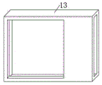
fig. 6 is a schematic view of the wind guiding housing of the present invention.
In the figure: 1. a display screen main body; 2. a first mounting case; 3. an elastic mechanism; 31. a fixing frame; 32. a card slot; 33. a spring slot; 34. extruding the frame; 35. a slide bar; 36. a compression spring; 4. an outer frame; 5. filtering with a screen; 6. a fixing plate; 7. a cavity; 8. a limiting plate; 9. a sliding frame; 10. pulling a plate; 11. a second mounting case; 12. a fan; 13. wind-guiding shell.
Detailed Description
The technical solutions in the embodiments of the present invention will be clearly and completely described below with reference to the drawings in the embodiments of the present invention, and it is obvious that the described embodiments are only a part of the embodiments of the present invention, and not all of the embodiments. All other embodiments, which can be derived by a person skilled in the art from the embodiments given herein without making any creative effort, shall fall within the protection scope of the present invention.
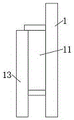
Referring to fig. 1-6, the present invention provides a technical solution: a LED display screen with a cooling structure comprises a display screen main body 1, wherein heat dissipation holes are formed in two sides of the upper end of the display screen main body 1, a first mounting shell 2 is fixedly connected to the outer side of the heat dissipation holes in one side of the upper end of the display screen main body 1, an elastic mechanism 3 is mounted in the middle of the inner side of the first mounting shell 2, an outer frame 4 is clamped in part of the first mounting shell 2 above the elastic mechanism 3, a filter screen 5 is fixedly connected to the inner part of the outer frame 4, fixing plates 6 are fixedly connected to the middle parts of the front and back sides of the upper end of the outer frame 4, cavities 7 are formed between the inner and outer walls of the front and back parts of the two sides of the outer frame 4, a limiting plate 8 is arranged inside each cavity 7, one side, close to the middle part of the first mounting shell 2, of each limiting plate 8 penetrates through and is slidably connected to the side wall of the corresponding cavity 7, one side, close to the middle part of the heat dissipation holes of the first mounting shell 2 abuts against the upper end of the outer frame 4, a second mounting shell 11 is fixedly connected to the outer part of the other side of the upper end of the display screen main body 1, the fan 12 is fixedly connected inside the second mounting shell 11, and when the display screen is used, air in the display screen main body 1 is discharged through the fan 12 to cool the inside of the display screen main body 1;
elastic mechanism 3 includes fixed frame 31, fixed frame 31 fixed connection is in the inside of first installation shell 2, draw-in groove 32 has been seted up to the upper end of fixed frame 31, a plurality of spring grooves 33 have all been seted up on both sides and the front and back inner wall of the inside lower extreme of draw-in groove 32, the equal fixedly connected with compression spring 36 in inside of a plurality of spring grooves 33, the common fixedly connected with extrusion frame 34 in upper end of a plurality of compression spring 36, extrusion frame 34 sliding connection is in the inside upper end of draw-in groove 32, accessible extrusion frame 34 extrudes frame 4 during the use, pull out frame 4 from first installation shell 2 when clearing up after convenient.
The parts of the limit plates 8 in the cavities 7 are sleeved with sliding frames 9 and fixedly connected with the sliding frames 9, the sliding frames 9 are connected inside the cavities 7 in a sliding mode, the limit plates 8 can slide inside the cavities 7 in positions conveniently, the upper ends of the second mounting shells 11 are fixedly connected with air guide shells 13, air outlets are formed in the side walls of the back faces of the air guide shells 13, openings of the second mounting shells 11 can be blocked conveniently, air exhaust directions can be changed, sliding rods 35 are inserted inside compression springs 36, the upper ends of the sliding rods 35 are fixedly connected to the lower ends of the extrusion frames 34, the lower ends of the sliding rods 35 penetrate through and are connected to the side walls of the lower ends of the spring grooves 33 on the same side in a sliding mode, movement tracks of the extrusion frames 34 can be fixed conveniently, the situation that the extrusion frames 34 incline when moving is avoided, the distance between the upper ends and the lower ends of the extrusion frames 34 is smaller than the distance between the upper ends and the lower ends of the clamping grooves 32, and the upper ends of the extrusion frames 34 and the upper ends of the fixing frames 31 are level, be convenient for extrude frame 4, one side that first installation shell 2 middle part was kept away from to limiting plate 8 all runs through and sliding connection on the lateral wall at place cavity 7, and the equal fixedly connected with arm-tie 10 in one side that first installation shell 2 middle part was kept away from to limiting plate 8 stimulates limiting plate 8 when being convenient for clear up, receives limiting plate 8 in the lateral wall of first installation shell 2.
Specifically, when the utility model is used, a power supply is switched on, the fan 12 sucks the air in the display screen main body 1 into the second mounting shell 11, then the air is discharged through the air guide shell 13, the heat in the display screen main body 1 is taken away, the purposes of cooling are achieved, the external air can pass through the first mounting shell 2 and enter the display screen main body 1 through the same-side heat dissipation holes, the air is ensured to flow in the display screen main body 1, in the process, the filter screen 5 in the first mounting shell 2 can filter out foreign matters such as dust in the air, the foreign matters such as dust are prevented from entering the display screen main body 1 and damaging electronic elements in the display screen main body 1, then when the filter screen 5 is cleaned, the limiting plate 8 is pulled to the direction far away from the middle part of the first mounting shell 2 through the pull plate 10, the limiting plate 8 is received in the side wall of the first mounting shell 2, and the outer frame 4 provided with the filter screen 5 is pushed by the extrusion frame 34 to partially eject the first mounting shell 2, then accessible fixed plate 6 is pulled out frame 4 from the inside of first installation shell 2, the foreign matter of dust class on the clearance filter screen 5, during later installation, go into first installation shell 2 with frame 4 card again, frame 4 will extrude frame 34 and extrude in draw-in groove 32 completely, and extrusion frame 34 then constantly extrudees compression spring 36, then push back original position with limiting plate 8, support limiting plate 8 on frame 4, fix frame 4 can in the inside of first installation shell 2.
In the description of the present invention, it is to be understood that the terms "coaxial", "bottom", "one end", "top", "middle", "other end", "upper", "one side", "top", "inner", "front", "center", "both ends", and the like, indicate orientations or positional relationships based on those shown in the drawings, and are only for convenience of description and simplicity of description, and do not indicate or imply that the referenced device or element must have a particular orientation, be constructed and operated in a particular orientation, and thus, are not to be construed as limiting the present invention.
Furthermore, the terms "first", "second", "third", "fourth" are used for descriptive purposes only and are not to be construed as indicating or implying a relative importance or implicitly indicating the number of technical features indicated, whereby the features defined as "first", "second", "third", "fourth" may explicitly or implicitly include at least one such feature.
In the present invention, unless otherwise expressly specified or limited, the terms "mounted," "disposed," "connected," "secured," "screwed" and the like are to be construed broadly, e.g., as meaning fixedly connected, detachably connected, or integrally formed; can be mechanically or electrically connected; the terms may be directly connected or indirectly connected through an intermediate, and may be communication between two elements or interaction relationship between two elements, unless otherwise specifically limited, and the specific meaning of the terms in the present invention will be understood by those skilled in the art according to specific situations.
Although embodiments of the present invention have been shown and described, it will be appreciated by those skilled in the art that changes, modifications, substitutions and alterations can be made in these embodiments without departing from the principles and spirit of the utility model, the scope of which is defined in the appended claims and their equivalents.
Claims (6)
1. The utility model provides a LED display screen with cooling structure, a serial communication port, including display screen main part (1), the louvre has all been seted up to the upper end both sides of display screen main part (1), the first installation shell (2) of the louvre outside fixedly connected with of display screen main part (1) upper end one side, the inboard mid-mounting of first installation shell (2) has elastic mechanism (3), the joint has frame (4) in the first installation shell (2) of part of elastic mechanism (3) top, the inside fixedly connected with filter screen (5) of frame (4), the equal fixedly connected with fixed plate (6) in side middle part around frame (4) upper end, cavity (7) have all been seted up between the inside and outside wall of frame (4) both sides front and back, the inside of cavity (7) all is equipped with limiting plate (8), one side that limiting plate (8) are close to first installation shell (2) middle part all runs through and sliding connection is at the lateral wall of place cavity (7) is in one side One side, close to the middle part of the first mounting shell (2), of the limiting plate (8) abuts against the upper end of the outer frame (4), a second mounting shell (11) is fixedly connected to the outer part of a radiating hole in the other side of the upper end of the display screen main body (1), and a fan (12) is fixedly connected to the inner part of the second mounting shell (11);
elastic mechanism (3) are including fixed frame (31), fixed frame (31) fixed connection is in the inside of first installation shell (2), draw-in groove (32) have been seted up to the upper end of fixed frame (31), a plurality of spring grooves (33), a plurality of all seted up on the both sides of the inside lower extreme of draw-in groove (32) and the front and back inner wall the equal fixedly connected with compression spring (36) in inside of spring groove (33), it is a plurality of the common fixedly connected with extrusion frame (34) in upper end of compression spring (36), extrusion frame (34) sliding connection is in the inside upper end of draw-in groove (32).
2. The LED display screen with the cooling structure according to claim 1, wherein: the inside of compression spring (36) all inserts and is equipped with slide bar (35), the equal fixed connection in the lower extreme of extrusion frame (34) in upper end of slide bar (35), the lower extreme of slide bar (35) all runs through and sliding connection is on the lower extreme lateral wall of homonymy spring groove (33).
3. The LED display screen with the cooling structure according to claim 1, wherein: the distance between the upper end and the lower end of the extrusion frame (34) is smaller than the distance between the upper end and the lower end of the clamping groove (32), and the upper end of the extrusion frame (34) is flush with the upper end of the fixing frame (31).
4. The LED display screen with the cooling structure according to claim 1, wherein: one side of the limiting plate (8) far away from the middle part of the first installation shell (2) is penetrated through and connected to the side wall of the cavity (7) in a sliding mode, and one side of the limiting plate (8) far away from the middle part of the first installation shell (2) is fixedly connected with a pulling plate (10).
5. The LED display screen with the cooling structure according to claim 1, wherein: the parts of the limiting plates (8) in the cavities (7) are all sleeved with sliding frames (9) fixedly connected with the limiting plates, and the sliding frames (9) are all connected inside the cavities (7) in a sliding mode.
6. The LED display screen with the cooling structure according to claim 1, wherein: the upper end of the second mounting shell (11) is fixedly connected with an air guide shell (13), and an air outlet is formed in the side wall of the back face of the air guide shell (13).
Priority Applications (1)
| Application Number | Priority Date | Filing Date | Title |
|---|---|---|---|
| CN202122739792.2U CN216287404U (en) | 2021-11-10 | 2021-11-10 | LED display screen with cooling structure |
Applications Claiming Priority (1)
| Application Number | Priority Date | Filing Date | Title |
|---|---|---|---|
| CN202122739792.2U CN216287404U (en) | 2021-11-10 | 2021-11-10 | LED display screen with cooling structure |
Publications (1)
| Publication Number | Publication Date |
|---|---|
| CN216287404U true CN216287404U (en) | 2022-04-12 |
Family
ID=81007620
Family Applications (1)
| Application Number | Title | Priority Date | Filing Date |
|---|---|---|---|
| CN202122739792.2U Active CN216287404U (en) | 2021-11-10 | 2021-11-10 | LED display screen with cooling structure |
Country Status (1)
| Country | Link |
|---|---|
| CN (1) | CN216287404U (en) |
-
2021
- 2021-11-10 CN CN202122739792.2U patent/CN216287404U/en active Active
Similar Documents
| Publication | Publication Date | Title |
|---|---|---|
| CN101090626A (en) | Dust-proof electric cabinet | |
| CN201064064Y (en) | Dustproof electric cabinet | |
| CN102023683B (en) | Server cabinet | |
| CN216287404U (en) | LED display screen with cooling structure | |
| CN112752468B (en) | Card insertion type big data cabinet | |
| CN216490840U (en) | Multifunctional computer network safety control device | |
| CN212765768U (en) | Fill electric pile heat dissipation mechanism | |
| CN214755023U (en) | Intelligent power supply and distribution device | |
| CN114513936A (en) | Electric power cabinet with warning function | |
| CN114171819A (en) | Energy storage cabinet | |
| CN211351295U (en) | Dustproof heat dissipation variable frequency power supply switch board | |
| CN220795726U (en) | Super integration all-in-one with dustproof heat dissipation | |
| CN214901558U (en) | Embedded control panel for entrance guard | |
| CN216671816U (en) | Energy storage integration box with electric core protection | |
| CN219592697U (en) | Heat dissipation structure of turnover folding screen main board | |
| CN218104049U (en) | Heat dissipation rack for switch | |
| CN210297753U (en) | Intelligent network risk information filter | |
| CN219371834U (en) | Comprehensive photovoltaic distribution box with communication data acquisition function | |
| CN219202655U (en) | Four-screen display device with good heat dissipation effect | |
| CN220528438U (en) | Heat radiation structure of module power supply | |
| CN220341838U (en) | Power distribution cabinet with good heat dissipation effect for power management machine room | |
| CN213694455U (en) | Computer network communication cabinet | |
| CN220671892U (en) | Remote management system for server | |
| CN220808461U (en) | Extruded sheet processing cooling arrangement | |
| CN214014263U (en) | Switch machine case |
Legal Events
| Date | Code | Title | Description |
|---|---|---|---|
| GR01 | Patent grant | ||
| GR01 | Patent grant |