CN216284929U - Acrylic film transparency detection equipment - Google Patents
Acrylic film transparency detection equipment Download PDFInfo
- Publication number
- CN216284929U CN216284929U CN202122596745.7U CN202122596745U CN216284929U CN 216284929 U CN216284929 U CN 216284929U CN 202122596745 U CN202122596745 U CN 202122596745U CN 216284929 U CN216284929 U CN 216284929U
- Authority
- CN
- China
- Prior art keywords
- acrylic film
- probe
- symmetrical
- plate
- support
- Prior art date
- Legal status (The legal status is an assumption and is not a legal conclusion. Google has not performed a legal analysis and makes no representation as to the accuracy of the status listed.)
- Active
Links
Images



Landscapes
- Investigating Or Analysing Materials By Optical Means (AREA)
Abstract
The utility model discloses a device for detecting the transparency of an acrylic film, which relates to the technical field of film detection, wherein two symmetrical supports are arranged on one side of the top of a support plate, a screw rod penetrates through the two supports together, the outer part of the screw rod is in threaded connection with an adjusting frame, the top and the bottom of the adjusting frame are respectively provided with a first probe and a second probe which are symmetrical, a placing box is arranged on the top of the front side of the adjusting frame, a light transmittance tester is clamped in the placing box, and one end of the screw rod is connected with a handle. And the setting of magnet strip, when using, the quick installation of can being convenient for, the effectual steadiness of guaranteeing whole placing.
Description
Technical Field
The utility model relates to the technical field of film detection, in particular to acrylic film transparency detection equipment.
Background
At present, when the detection equipment for the transparency of the acrylic film is actually used, the acrylic film cannot be fixed, and the transparency cannot be uniformly detected, so that the accuracy of data is reduced.
SUMMERY OF THE UTILITY MODEL
Aiming at the defects of the prior art, the utility model provides acrylic film transparency detection equipment, which solves the problem that the existing acrylic film transparency detection equipment cannot fix an acrylic film and cannot detect the transparency uniformly in actual use, so that the accuracy of data is reduced.
In order to achieve the purpose, the utility model is realized by the following technical scheme: the acrylic film transparency detection equipment comprises a support base, wherein a detection assembly is mounted at the upper end of the support base, a frame plate is mounted in the middle of the top of the detection assembly, a support block is mounted at the corner of the inner side of the frame plate, and two symmetrical fixing assemblies are mounted at two ends of the top of the frame plate;
the detection assembly comprises a supporting plate installed at the upper end of a support seat, two symmetrical supports are installed on one side of the top of the supporting plate, a screw rod penetrates through the inside of each support, the outer portion of the screw rod is connected with an adjusting frame in a threaded mode, symmetrical first probes and symmetrical second probes are arranged at the top and the bottom of the adjusting frame respectively, a placement box is installed at the top of the front side of the adjusting frame, a light transmittance tester is clamped inside the placement box, and a handle is connected to one end of the screw rod.
As a further technical scheme, the fixing assembly comprises a micro cylinder and two symmetrical lever arms, one end of each lever arm forms a fixed connection structure together through a transverse plate, and the other end of each lever arm is provided with a pressing plate.
As a further technical scheme, two symmetrical limiting columns are respectively installed at two ends of the top of the frame plate, the tops of the limiting columns penetrate through the side wall of the transverse plate and extend to the outside, and magnet strips are embedded in the periphery of the bottom of the support base.
As a further technical scheme, a first through hole is formed in the middle of the inner portion of the supporting plate, the first through hole is located right below the first probe, and the telescopic end of the micro cylinder is connected with the transverse plate.
As a further technical scheme, a second through hole is formed in one end of the supporting plate and located between the two supports, one end of the adjusting frame penetrates through the second through hole, and the first probe and the second probe are in communication connection with the light transmittance tester through connecting wires.
As a further technical scheme, the other ends of the top and the bottom of the supporting plate are provided with a first linear sliding rail and a second linear sliding rail which are symmetrical, the outer parts of the first linear sliding rail and the second linear sliding rail are respectively connected with a first sliding seat and a second sliding seat in a sliding mode, and the first sliding seat and the second sliding seat are both connected with the other end of the adjusting frame.
Advantageous effects
The utility model provides a device for detecting the transparency of an acrylic film. Compared with the prior art, the method has the following beneficial effects:
1. the utility model provides an inferior gram force membrane transparency check out test set, drives screw rod drive's mode through the handle, under the effect of alignment jig, can drive the first probe and the second probe of luminousness tester, carries out reciprocal linear motion along the direction of first through-hole to be convenient for even the transparency that detects out inferior gram force membrane, improved the accuracy nature that detects, this simple structure easily operates simultaneously, and area is less, has improved the convenience of using.
2. The utility model provides an inferior gram force membrane transparency check out test set, through starting miniature cylinder, its flexible end can drive the clamp plate and push down under the effect of diaphragm and lever arm to can reach the effect fixed to inferior gram force membrane, and the setting of magnet strip, when using, can be convenient for install fast, the effectual steadiness of guaranteeing whole placing.
Drawings
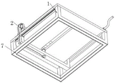
Fig. 1 is a schematic view of a first viewing angle structure of an acrylic film transparency detection apparatus;
FIG. 2 is a schematic diagram of a second view structure of an apparatus for detecting transparency of an acrylic film;
FIG. 3 is a schematic structural diagram of a detection assembly of an acrylic film transparency detection device;
FIG. 4 is a front view of a structure of a detection assembly of an acrylic film transparency detection device;
fig. 5 is a schematic structural view of a fixing component of an acrylic film transparency detecting apparatus.
In the figure: 1. a support base; 2. a detection component; 21. a support plate; 22. a support; 23. a screw; 24. an adjusting bracket; 25. a first probe; 26. a second probe; 27. placing the box; 28. a light transmittance tester; 29. a handle; 210. a first through hole; 211. a second through hole; 212. a first linear slide rail; 213. a second linear slide rail; 214. a first slider; 215. a second slide carriage; 216. a connecting wire; 3. a frame plate; 4. a support block; 5. a fixing assembly; 51. a micro cylinder; 52. a lever arm; 53. pressing a plate; 54. a transverse plate; 6. a limiting column; 7. and a magnet strip.
Detailed Description
The technical solutions in the embodiments of the present invention will be clearly and completely described below with reference to the drawings in the embodiments of the present invention, and it is obvious that the described embodiments are only a part of the embodiments of the present invention, and not all of the embodiments. All other embodiments, which can be derived by a person skilled in the art from the embodiments given herein without making any creative effort, shall fall within the protection scope of the present invention.
Referring to fig. 1-2, the present invention provides a technical solution of an apparatus for detecting transparency of an acrylic film: the utility model provides an inferior gram force membrane transparency check out test set, including a support frame 1, detection component 2 is installed to the upper end of support frame 1, install framed panel 3 in the middle of detection component 2's the top, tray 4 is installed to framed panel 3's inboard corner, two symmetrical fixed subassemblies 5 are then installed at its top both ends, two symmetrical spacing posts 6 are installed respectively at framed panel 3's top both ends, the lateral wall of diaphragm 54 is run through at spacing post 6's top and extends to the outside, the bottom of support frame 1 is embedded all around to have magnet strip 7, the setting of magnet strip 7, can be when using, be convenient for install fast, the effectual steadiness of placing of having ensured, and the setting of spacing post 6, can play the effect of location for the lift of clamp plate 53.
Referring to fig. 3-4, the detecting assembly 2 includes a supporting plate 21 installed at the upper end of the bracket holder 1, two symmetrical supporting seats 22 are installed at one side of the top of the supporting plate 21, a screw 23 penetrates through the insides of the two supporting seats 22 together, an adjusting bracket 24 is connected to the outside of the screw 23 through a thread, a first probe 25 and a second probe 26 are symmetrically installed at the top and the bottom of the adjusting bracket 24 respectively, a placing box 27 is installed at the top of the front side of the adjusting bracket 24, a light transmittance tester 28 is clamped inside the placing box 27, one end of the screw 23 is connected with a handle 29, a first through hole 210 is opened in the middle inside of the supporting plate 21, the first through hole 210 is located under the first probe 25, a second through hole 211 is opened at one end of the supporting plate 21 and located between the two supporting seats 22, one end of the adjusting bracket 24 penetrates inside the second through hole 211, the first probe 25 and the second probe 26 are both in communication connection with the light transmittance tester 28 through a connecting wire 216, symmetrical first linear slide rail 212 and second linear slide rail 213 are installed to the top of backup pad 21 and the bottom other end, the outside sliding connection respectively of first linear slide rail 212 and second linear slide rail 213 has first slide 214 and second slide 215, first slide 214 and second slide 215 all meet with the other end of alignment jig 24, drive the driven mode of screw 23 through handle 29, under the effect of alignment jig 24, can drive first probe 25 and second probe 26 of luminousness tester 28, carry out reciprocal linear motion along the direction of first through-hole 210, thereby be convenient for even detection out the transparency of ya keli membrane.
Referring to fig. 5, the fixing assembly 5 includes a micro cylinder 51 and two symmetrical lever arms 52, one end of each of the two lever arms 52 forms a fixed connection structure together through a horizontal plate 54, the other end of each of the two lever arms is provided with a pressing plate 53, the telescopic end of the micro cylinder 51 is connected with the horizontal plate 54, the pressing plate 53 is located right above the support block 4, and the size of the two lever arms is the same, and by starting the micro cylinder 51, the telescopic end thereof can drive the pressing plate 53 to press down under the action of the horizontal plate 54 and the lever arms 52, thereby achieving the effect of fixing the acrylic film.
Working principle of the light transmittance tester 28: when a parallel light beam is incident on a medium (such as transparent plastic), the light beam changes direction (diffusion and segregation) due to the non-uniformity of the optical properties of the material, surface defects, the non-uniformity of the internal structure, the presence of air bubbles and impurities, etc., and a part of disorderly light is generated and called scattered light.
Test principle of the light transmittance tester 28: the water vapor transmission rate and other parameters of the sample are determined by measuring the change of the weight of the see-through cup with time at a certain temperature by forming a specific temperature difference on both sides of the sample, and allowing the water vapor to permeate through the side of the sample where the sample enters the drying process.
The working principle of the utility model is as follows: when in use, the whole detection equipment can be arranged on a tabletop made of ferrous materials under the action of the magnet bars 7, then the acrylic film is taken out, the four corners of the acrylic film are placed on the corresponding support blocks 4, at this time, the micro air cylinder 51 is started, the telescopic end can apply a pulling force to the cross plate 54, and the pressing plate 53 can be driven to press downwards under the action of the lever arm 52 until the four corners of the acrylic film are fixed, can ensure the stability of placement, and finally, the handle 29 is rotated to drive the screw 23 to rotate, under the action of the adjusting bracket 24, the first probe 25 and the second probe 26 at the top and the bottom can be driven to move along the directions of the first linear slide rail 212 and the second linear slide rail 213, the detecting ends of the first probe 25 and the second probe 26 can be projected on the acrylic film through the first through hole 210, so that the transparency of the acrylic film can be uniformly detected, and the transparency value is put on the display screen of the light transmittance tester 28.
In the present embodiment, the light transmittance tester 28 is model JC506-05, and the structural features, the operating principle and the specific circuit structure electrically connected to the outside are all the prior art, and will not be described in detail herein.
Claims (6)
1. The acrylic film transparency detection equipment comprises a support base (1) and is characterized in that a detection assembly (2) is mounted at the upper end of the support base (1), a frame plate (3) is mounted in the middle of the top of the detection assembly (2), a support block (4) is mounted at the inner side corner of the frame plate (3), and two symmetrical fixing assemblies (5) are mounted at two ends of the top of the frame plate;
detection subassembly (2) are including installing backup pad (21) in support seat (1) upper end, two symmetrical support (22) are installed to top one side of backup pad (21), two the inside of support (22) has run through screw rod (23) jointly, the outside threaded connection of screw rod (23) has alignment jig (24), the top and the bottom of alignment jig (24) are provided with symmetrical first probe (25) and second probe (26) respectively, the front side top of alignment jig (24) is installed and is placed box (27), the inside block of placing box (27) has luminousness tester (28), the one end of screw rod (23) is connected with handle (29).
2. The acrylic film transparency detection device according to claim 1, wherein the fixing assembly (5) comprises a micro cylinder (51) and two symmetrical lever arms (52), one end of each lever arm (52) forms a fixed connection structure together through a transverse plate (54), and the other end is provided with a pressing plate (53).
3. The acrylic film transparency detection device according to claim 2, wherein two symmetrical limiting columns (6) are respectively installed at two ends of the top of the frame plate (3), the top of each limiting column (6) penetrates through the side wall of the transverse plate (54) and extends to the outside, and magnet strips (7) are embedded around the bottom of the support base (1).
4. The acrylic film transparency detection device according to claim 2, wherein a first through hole (210) is formed in the middle of the inside of the support plate (21), the first through hole (210) is located right below the first probe (25), and the telescopic end of the micro cylinder (51) is connected with the transverse plate (54).
5. The acrylic film transparency detection device according to claim 1, wherein a second through hole (211) is formed at one end of the support plate (21) and between the two supports (22), one end of the adjusting frame (24) penetrates through the second through hole (211), and the first probe (25) and the second probe (26) are both in communication connection with a light transmittance tester (28) through a connection line (216).
6. The acrylic film transparency detection device according to claim 1, wherein the other ends of the top and the bottom of the support plate (21) are provided with a first linear slide rail (212) and a second linear slide rail (213) which are symmetrical, the outer parts of the first linear slide rail (212) and the second linear slide rail (213) are respectively connected with a first slide carriage (214) and a second slide carriage (215) in a sliding manner, and the first slide carriage (214) and the second slide carriage (215) are connected with the other end of the adjusting frame (24).
Priority Applications (1)
| Application Number | Priority Date | Filing Date | Title |
|---|---|---|---|
| CN202122596745.7U CN216284929U (en) | 2021-10-27 | 2021-10-27 | Acrylic film transparency detection equipment |
Applications Claiming Priority (1)
| Application Number | Priority Date | Filing Date | Title |
|---|---|---|---|
| CN202122596745.7U CN216284929U (en) | 2021-10-27 | 2021-10-27 | Acrylic film transparency detection equipment |
Publications (1)
| Publication Number | Publication Date |
|---|---|
| CN216284929U true CN216284929U (en) | 2022-04-12 |
Family
ID=81072516
Family Applications (1)
| Application Number | Title | Priority Date | Filing Date |
|---|---|---|---|
| CN202122596745.7U Active CN216284929U (en) | 2021-10-27 | 2021-10-27 | Acrylic film transparency detection equipment |
Country Status (1)
| Country | Link |
|---|---|
| CN (1) | CN216284929U (en) |
-
2021
- 2021-10-27 CN CN202122596745.7U patent/CN216284929U/en active Active
Similar Documents
| Publication | Publication Date | Title |
|---|---|---|
| CN203414208U (en) | A relay reed pressure and gap testing device based on machine vision | |
| CN106328556A (en) | Automatic tester for wafer | |
| CN216284929U (en) | Acrylic film transparency detection equipment | |
| CN209043248U (en) | A kind of mobile phone screen size detection machine | |
| CN211653341U (en) | Extensive applicability's LCD panel tester | |
| CN210953862U (en) | Liquid crystal display scratch detection device | |
| CN218822013U (en) | Automatic detection tool for automobile skylight support | |
| CN209355985U (en) | A kind of vision inspection apparatus with light filling function | |
| CN218445193U (en) | Polaroid precision detector | |
| CN208399848U (en) | A kind of verifying attachment | |
| CN114759421B (en) | Plug tool of curved surface product | |
| CN216247721U (en) | Automatic backlight appearance detection equipment | |
| CN217385626U (en) | Current test fixture with voltage reduction function | |
| CN216247125U (en) | Multi-unit intelligent testing device for touch screen | |
| CN213812184U (en) | Cell-phone center plane degree detects machine | |
| CN210374963U (en) | Glass flatness testing device | |
| CN211122533U (en) | Shading testing arrangement is used in processing of polyimide film | |
| CN210893998U (en) | Full-automatic liquid absorption performance tester | |
| CN208476776U (en) | A kind of UV, visible light light-dividing device | |
| CN111024371A (en) | HUD front windshield detection device | |
| CN215678043U (en) | Device for testing binding power of laminated battery string | |
| CN220380436U (en) | Wind power detection device of electric fan | |
| CN217981030U (en) | Horizontal computer type thrust machine | |
| CN218068165U (en) | Attenuator quick positioning test device | |
| CN110588002A (en) | CCD screen pasting machine |
Legal Events
| Date | Code | Title | Description |
|---|---|---|---|
| GR01 | Patent grant | ||
| GR01 | Patent grant |