CN216279249U - Screw rod piece with split type nut - Google Patents
Screw rod piece with split type nut Download PDFInfo
- Publication number
- CN216279249U CN216279249U CN202122410512.3U CN202122410512U CN216279249U CN 216279249 U CN216279249 U CN 216279249U CN 202122410512 U CN202122410512 U CN 202122410512U CN 216279249 U CN216279249 U CN 216279249U
- Authority
- CN
- China
- Prior art keywords
- groove
- nut
- screw rod
- lower fixing
- plate
- Prior art date
- Legal status (The legal status is an assumption and is not a legal conclusion. Google has not performed a legal analysis and makes no representation as to the accuracy of the status listed.)
- Active
Links
Images


Landscapes
- Earth Drilling (AREA)
Abstract
The utility model discloses a lead screw component with a split nut, which comprises a screw rod, wherein an upper nut and a lower fixing plate are arranged on the outer side of the screw rod close to the top, the upper nut is positioned above the lower fixing plate, a groove is formed in the bottom end of the upper nut close to the middle part, a receiving groove is formed in one side of the inner wall of the groove, a clamping component is arranged in the receiving groove, a rope hanging component is arranged between the upper nut and the lower fixing plate, a convex block is arranged on the top end of the lower fixing plate close to the right lower part of the groove, the clamping component comprises a connecting plate, a spring is arranged on one side of the connecting plate, a clamping rod is arranged at one end, far away from the connecting plate, of the spring, the rope hanging component comprises two groups of rectangular plates, and side plates are arranged on two sides of the two groups of rectangular plates; according to the screw rod piece with the split nuts, after the nuts are disassembled, the connecting parts are lifted between the two groups of nuts, so that the loss is avoided, and meanwhile, when the nuts are mutually installed, the connecting parts are added, and the loosening condition is reduced.
Description
Technical Field
The utility model relates to the field of screw rod pieces, in particular to a screw rod piece with a split type nut.
Background
The screw rod piece of the split nut is a device for realizing conversion between rotary motion and linear motion, and is widely applied to the field of machining, for example, a screw rod nut mechanism is applied to mechanical equipment such as a common lathe, a common milling machine, a manual key machine, a wire cutting machine and the like;
the existing split nut screw rod piece has certain defects to be improved when in use, and when the upper nut is connected with the lower fixing plate, the existing split nut screw rod piece is usually connected with the groove only through the bump, so that the connection is unstable, looseness occurs, and the use defects exist; the lead screw spare of current split type nut dismantles the back with two sets of nuts, lacks the part of connection between, leads to when placing, loses easily, is unfavorable for the use.
SUMMERY OF THE UTILITY MODEL
The utility model mainly aims to provide a screw rod piece with a split nut, which can effectively solve the problem that the screw rod piece of the existing split nut in the background technology is usually connected with a groove only through a convex block when an upper nut is connected with a lower fixing plate, so that the connection is unstable, and the screw rod piece is loosened and has use defects; the lead screw spare of current split type nut dismantles the back with two sets of nuts, lacks the part of connection between, leads to when placing, loses easily, is unfavorable for the technical problem who uses.
In order to achieve the purpose, the utility model adopts the technical scheme that:
a lead screw piece with a split type nut comprises a screw, wherein an upper nut and a lower fixing plate are mounted on the outer side of the screw close to the top, the upper nut is located above the lower fixing plate, a groove is formed in the bottom end of the upper nut close to the middle, a containing groove is formed in one side of the inner wall of the groove, a clamping assembly is mounted inside the containing groove, a rope hanging assembly is mounted between the upper nut and the lower fixing plate, and a convex block is mounted on the top end of the lower fixing plate close to the position under the groove;
the joint subassembly includes the connecting plate, the spring is installed to one side of connecting plate, the spring is kept away from the one end of connecting plate and is installed the kelly.
As a further scheme of the utility model, the hanging rope assembly comprises two groups of rectangular plates, side plates are arranged on two sides of each group of rectangular plates, an elastic belt is arranged between the two groups of rectangular plates, and snap buttons are arranged between the rear end of the elastic belt and the two groups of rectangular plates.
As a further scheme of the utility model, clamping grooves are formed in the two sides of the protruding block close to the bottom in a penetrating mode, the outer sides of the clamping rods are connected to the inner portions of the clamping grooves in a contact mode, and balls are mounted on the inner walls of the upper screw cap and the lower fixing plate.
As a further scheme of the utility model, a limit groove is formed in one end, close to the clamping rod, of the other side of the inner wall of the accommodating groove, and the width and the length of one end of the clamping rod are equal to those of the accommodating groove.
As a further scheme of the utility model, screw holes are formed in one side of the connecting plate close to two ends in a penetrating mode, and bolts are mounted on the outer sides of the two groups of screw holes.
As a further scheme of the utility model, the rear end of the elastic band is fixedly connected to the front ends of the two groups of rectangular plates by two groups of snap fasteners respectively.
Compared with the prior art, the utility model has the following beneficial effects: according to the utility model, by installing the clamping assembly, the clamping rod is fixed on one side of the inner wall of the accommodating groove by using the connecting plate, and is pressed towards one side, so that the two sides of the clamping rod are accommodated into the accommodating groove formed in one side of the inner wall of the groove by using the spring, and further, the inner wall of the groove can be meshed with the outer side of the bump;
hang the rope subassembly through the installation, when nut and bottom plate are being dismantled, two sets of curb plates that the rear end of two sets of rectangular plates passes through respectively are fixed in the outside at last nut and bottom plate, when last nut rolls out the screw rod completely, fix the front end at two sets of rectangular plates respectively through the snap with the rear end both sides of elastic webbing, it installs the structure to make to be connected between last nut and the bottom plate, hang the rope subassembly through the setting after dismantling split type nut, adapting unit has been increased between two sets of nuts, make two sets of nuts difficult losses after dismantling, reduce resource loss.
Drawings
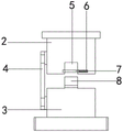
FIG. 1 is a schematic view of the overall structure of a screw member with a split nut according to the present invention;
FIG. 2 is an assembly view of an upper nut and a lower fixing plate of a screw member with a split nut according to the present invention;
FIG. 3 is a schematic structural view of a clamping assembly of a screw member with a split nut according to the present invention;
fig. 4 is a schematic structural view of a lanyard assembly of the snap-fit assembly of the rod-and-wire member with the split nut of the present invention.
In the figure: 1. a screw; 2. screwing a nut; 3. a lower fixing plate; 4. a lanyard assembly; 5. a groove; 6. a receiving groove; 7. a clamping assembly; 8. a bump; 9. a clamping rod; 10. a spring; 11. a connecting plate; 12. a rectangular plate; 13. a side plate; 14. snapping; 15. an elastic band.
Detailed Description
In order to make the technical means, the creation characteristics, the achievement purposes and the effects of the utility model easy to understand, the utility model is further described with the specific embodiments.
As shown in fig. 1-4, a lead screw with a split nut comprises a screw 1, an upper nut 2 and a lower fixing plate 3 are mounted on the outer side of the screw 1 close to the top, the upper nut 2 is positioned above the lower fixing plate 3, a groove 5 is formed in the bottom end of the upper nut 2 close to the middle, a receiving groove 6 is formed in one side of the inner wall of the groove 5, a clamping assembly 7 is mounted inside the receiving groove 6, a rope hanging assembly 4 is mounted between the upper nut 2 and the lower fixing plate 3, and a convex block 8 is mounted on the top end of the lower fixing plate 3 close to the right below the groove 5;
the clamping assembly 7 comprises a connecting plate 11, a spring 10 is installed on one side of the connecting plate 11, and a clamping rod 9 is installed at one end, far away from the connecting plate 11, of the spring 10.
In this embodiment, in order to add the connecting component between the two sets of nuts, the hanging rope assembly 4 includes two sets of rectangular plates 12, side plates 13 are installed on two sides of the two sets of rectangular plates 12, an elastic band 15 is installed between the two sets of rectangular plates 12, and a snap 14 is installed between the rear end of the elastic band 15 and the two sets of rectangular plates 12.
In this embodiment, in order to make the nut can get the outside at screw rod 1 and rotate, the draw-in groove has been seted up by the bottom penetration to the both sides of lug 8, and the outside contact of kelly 9 is connected in the inside of draw-in groove, goes up the ball that the inner wall of nut 2 and bottom plate 3 all installed.
In this embodiment, in order to limit the external position of the clamping rod 9 after the external position is determined, a limit groove is formed at one end of the other side of the inner wall of the accommodating groove 6 close to the clamping rod 9, and the width and length of one end of the clamping rod 9 are equal to those of the accommodating groove 6.
In this embodiment, in order to provide a connection fixing structure, a screw hole is provided through both ends of one side of the connecting plate 11, and a bolt is installed on the outer side of each of the two sets of screw holes.
In the present embodiment, in order to fixedly connect the rear end of the elastic band 15 to the front ends of the two sets of rectangular plates 12, the rear end of the elastic band 15 is fixedly connected to the front ends of the two sets of rectangular plates 12 through two sets of snaps 14.
It should be noted that, the utility model is a screw rod with split nut, when in use, first mutually engage the upper nut 2 and one end of the lower fixing plate 3, make the groove 5 opened at the bottom end of the upper nut 2 fit the outside of the convex block 8 installed at the top end of the lower fixing plate 3, to form a fixed connection, and when the upper nut 2 is located above the lower fixing plate 3, fix the clamping rod 9 on one side of the inner wall of the accommodating groove 6 by the connecting plate 11, at the same time press it to one side, make its two sides accommodated into the accommodating groove 6 opened at one side of the inner wall of the groove 5 by the spring 10, and then the inner wall of the groove 5 can engage on the outside of the convex block 8, when the convex block 8 is completely immersed into the groove 5, the clamping rod 9 rebounds by the spring 10, passes through the clamping groove opened at two sides of the convex block 8, one end of which is against the spacing groove opened at the other side of the inner wall of the groove 5, thereby fixing the convex block 8 in the groove 5, at this moment, the upper nut 2 and the lower fixing plate 3 can be simultaneously rotated to be rotated outside the screw rod 1 through the balls, the fixed distance is adjusted, when the upper nut 2 and the lower fixing plate 3 are disassembled, the two groups of side plates 13, through which the rear ends of the two groups of rectangular plates 12 respectively pass, are fixed outside the upper nut 2 and the lower fixing plate 3, when the upper nut 2 is completely rotated out of the screw rod 1, the two sides of the rear end of the elastic band 15 are respectively fixed at the front ends of the two groups of rectangular plates 12 through the snap fasteners 14, and therefore the structure is connected and installed between the upper nut 2 and the lower fixing plate 3.
According to the utility model, by installing the clamping assembly 7, the clamping rod 9 is fixed on one side of the inner wall of the accommodating groove 6 by using the connecting plate 11, and is pressed towards one side, so that two sides of the clamping rod are accommodated into the accommodating groove 6 formed in one side of the inner wall of the groove 5 by using the spring 10, and further the inner wall of the groove 5 can be meshed on the outer side of the lug 8, after the lug 8 is completely immersed into the groove 5, the clamping rod 9 rebounds by using the spring 10 again, passes through the clamping groove formed in the two sides of the lug 8 and penetrates through the other side of the inner wall of the groove 5, one end of the clamping rod abuts against the limiting groove formed in the other side of the inner wall of the groove 5, so that the lug 8 is fixed in the groove 5, when the split nut is fixed by arranging the clamping assembly 7, the connecting part between the nuts is increased, and meanwhile, the position of the nut is limited during meshing, the loosening condition is reduced, and the practicability of the wire rod piece is improved; hang rope subassembly 4 through the installation, when nut 2 and bottom plate 3 are being dismantled, two sets of curb plates 13 that the rear end of two sets of rectangular plates 12 passes through respectively are fixed in the outside at last nut 2 and bottom plate 3, when last nut 2 rolls out screw rod 1 completely, fix the front end at two sets of rectangular plates 12 respectively through snap 14 with the rear end both sides of elastic band 15, it installs the structure to make to be connected between last nut 2 and the bottom plate 3, hang rope subassembly 4 through setting up and after dismantling split type nut, adapting unit has been increased between two sets of nuts, make two sets of nuts difficult for losing after dismantling, reduce resource loss.
The foregoing shows and describes the general principles and broad features of the present invention and advantages thereof. It will be understood by those skilled in the art that the present invention is not limited to the embodiments described above, which are described in the specification and illustrated only to illustrate the principle of the present invention, but that various changes and modifications may be made therein without departing from the spirit and scope of the present invention, which fall within the scope of the utility model as claimed. The scope of the utility model is defined by the appended claims and equivalents thereof.
Claims (6)
1. The utility model provides a silk member with split type nut, includes screw rod (1), its characterized in that: an upper nut (2) and a lower fixing plate (3) are mounted on the outer side of the screw rod (1) by the top, the upper nut (2) is located above the lower fixing plate (3), a groove (5) is formed in the bottom end of the upper nut (2) by the middle portion, a containing groove (6) is formed in one side of the inner wall of the groove (5), a clamping assembly (7) is mounted inside the containing groove (6), a rope hanging assembly (4) is mounted between the upper nut (2) and the lower fixing plate (3), and a convex block (8) is mounted on the top end of the lower fixing plate (3) by the right below the groove (5);
joint subassembly (7) are including connecting plate (11), spring (10) are installed to one side of connecting plate (11), kelly (9) are installed to the one end that connecting plate (11) were kept away from in spring (10).
2. The screw rod piece with the split nut of claim 1, wherein: hang rope subassembly (4) and include two sets of rectangular plate (12), it is two sets of curb plate (13) are all installed to the both sides of rectangular plate (12), and install elastic webbing (15) between two sets of rectangular plate (12), all install snap (14) between the rear end of elastic webbing (15) and two sets of rectangular plate (12).
3. The screw rod piece with the split nut of claim 1, wherein: the both sides of lug (8) are leaned on the bottom to run through and have been seted up the draw-in groove, and the outside contact of kelly (9) is connected in the inside of draw-in groove, goes up the ball that the inner wall of nut (2) and bottom plate (3) all installed.
4. The screw rod piece with the split nut of claim 1, wherein: the other side of the inner wall of the accommodating groove (6) is provided with a limiting groove close to one end of the clamping rod (9), and the width and the length of one end of the clamping rod (9) are equal to those of the accommodating groove (6).
5. The screw rod piece with the split nut of claim 1, wherein: screw holes are formed in one side of the connecting plate (11) through both ends, and bolts are installed on the outer sides of the two groups of screw holes.
6. The screw rod piece with the split nut of claim 2, wherein: the rear end of the elastic band (15) is fixedly connected to the front ends of the two groups of rectangular plates (12) by two groups of snap buttons (14) respectively near two sides.
Priority Applications (1)
| Application Number | Priority Date | Filing Date | Title |
|---|---|---|---|
| CN202122410512.3U CN216279249U (en) | 2021-09-30 | 2021-09-30 | Screw rod piece with split type nut |
Applications Claiming Priority (1)
| Application Number | Priority Date | Filing Date | Title |
|---|---|---|---|
| CN202122410512.3U CN216279249U (en) | 2021-09-30 | 2021-09-30 | Screw rod piece with split type nut |
Publications (1)
| Publication Number | Publication Date |
|---|---|
| CN216279249U true CN216279249U (en) | 2022-04-12 |
Family
ID=81066168
Family Applications (1)
| Application Number | Title | Priority Date | Filing Date |
|---|---|---|---|
| CN202122410512.3U Active CN216279249U (en) | 2021-09-30 | 2021-09-30 | Screw rod piece with split type nut |
Country Status (1)
| Country | Link |
|---|---|
| CN (1) | CN216279249U (en) |
-
2021
- 2021-09-30 CN CN202122410512.3U patent/CN216279249U/en active Active
Similar Documents
| Publication | Publication Date | Title |
|---|---|---|
| CN216279249U (en) | Screw rod piece with split type nut | |
| CN211203582U (en) | Wisdom is video monitoring device of easy installation for building | |
| CN211523518U (en) | Bidirectional connecting piece for building steel structure | |
| CN214661432U (en) | Elastic plate fastening bolt | |
| CN217462844U (en) | Locking nut assembly that moves with multiple fastening structure | |
| CN213628419U (en) | Quick locking nut assembly | |
| CN216530037U (en) | Intelligent power distribution box with temperature monitoring function | |
| CN112431469B (en) | Anti-drop formula Y type tower head connecting piece convenient to installation is fixed | |
| CN220726050U (en) | Anti-falling glass door chuck connecting piece | |
| CN216478322U (en) | Bolt insulator, bolt assembly, fuel cell and electrolytic cell | |
| CN217355134U (en) | Improved screw | |
| CN216143039U (en) | High-temperature-resistant anti-seepage bolt | |
| CN220965154U (en) | Silicon microphone convenient for butt joint of protective shells | |
| CN211951146U (en) | Bolt with high anti-falling performance | |
| CN211737715U (en) | Nut | |
| CN220037219U (en) | Anti-reverse screw structure | |
| CN113668713B (en) | Assembly type integrated connecting device for construction equipment | |
| CN211076657U (en) | A anti-drop universal driving shaft for packagine machine | |
| CN218714179U (en) | Fixed subassembly of assembled aluminium veneer | |
| CN215567187U (en) | Anti-loose bolt and nut for electric power tower | |
| CN218266694U (en) | Bolt with anti-loosening function | |
| CN218548231U (en) | More firm composite contact | |
| CN212045804U (en) | Center thimble quick change device for injection molding machine | |
| CN220985478U (en) | Motor integrated protector convenient to install | |
| CN214146191U (en) | Waterproof rivet for building decoration |
Legal Events
| Date | Code | Title | Description |
|---|---|---|---|
| GR01 | Patent grant | ||
| GR01 | Patent grant |