CN216265073U - Burr removing device for aluminum casting machining - Google Patents
Burr removing device for aluminum casting machining Download PDFInfo
- Publication number
- CN216265073U CN216265073U CN202122995854.6U CN202122995854U CN216265073U CN 216265073 U CN216265073 U CN 216265073U CN 202122995854 U CN202122995854 U CN 202122995854U CN 216265073 U CN216265073 U CN 216265073U
- Authority
- CN
- China
- Prior art keywords
- fixed
- fixedly arranged
- grinding
- shell
- rod
- Prior art date
- Legal status (The legal status is an assumption and is not a legal conclusion. Google has not performed a legal analysis and makes no representation as to the accuracy of the status listed.)
- Active
Links
Images


Abstract
The utility model discloses a burr removing device for machining an aluminum casting, and particularly relates to the field of burr treatment, wherein the burr removing device comprises a base, wherein a fixed rod is fixedly arranged at the top of the base, a top plate is fixedly arranged at the top of the fixed rod, and a circular electric rail is fixedly arranged at the bottom of the top plate; the circular electric rail bottom is equipped with the track piece, the fixed hydraulic stem that is equipped with in track piece bottom, the hydraulic stem output is equipped with the motor, the motor output shaft is equipped with the pivot, the fixed baffle that is equipped with in pivot bottom, the fixed mechanism that rubs off that is equipped with in baffle bottom. By arranging the circular electric track and the grinding mechanism, the structure not only can grind the inside, but also can adjust the upper grinding shell and the lower grinding shell into large angles to semi-surround the edge position, so that the grinding angle is improved, the aluminum casting can be ground according to the burr angle of the aluminum casting, and the integrated removing effect can be realized when the burr of the circular aluminum casting is removed.
Description
Technical Field
The utility model relates to the technical field of burr treatment, in particular to a burr removing device for machining an aluminum casting.
Background
In the casting production process of aluminum casting products, due to the problems of long-time use and manufacturing precision of the die, certain gaps exist at the matching positions of the four side dies, when aluminum liquid is pressed into the die, a certain amount of aluminum liquid seeps out at the positions, burrs with certain thickness and height are formed, and equipment for grinding the burrs is called as burr removing equipment.
The utility model patent of patent application publication No. CN212824385U discloses an aluminum casting deburring device, which comprises a support plate and a polishing head; the utility model discloses a portable polishing machine, including base plate, backup pad, cylinder, movable plate, polishing head, motor, carrier platform, motor, support column, bottom plate, the backup pad is connected with the bottom plate through the support column, the vertical cylinder that is provided with of backup pad up end, cylinder piston rod top is connected with the movable plate, the support column runs through the movable plate, just the movable plate reciprocates along the support column, the polishing head is connected with the movable plate through the motor axis of rotation, the polishing head is corresponding with carrier platform position, the motor both sides are provided with down the air cylinder respectively, it is connected with the briquetting to push down air cylinder piston rod bottom. The utility model discloses an aluminum casting burring device realizes evenly polishing the realization product to the automatic burring of aluminum casting product, reduces staff's intensity of labour.
But when in actual use, this burring device is carrying out the burr to circular shape aluminium foundry goods and is got rid of, is difficult to polish it according to the unedged angle of aluminium foundry goods for can't accomplish the effect that the integration was got rid of when carrying out the deckle edge to circular shape aluminium foundry goods.
Disclosure of Invention
In order to overcome the defects in the prior art, the embodiment of the utility model provides a burr removing device for processing an aluminum casting, which is provided with a circular electric track and a grinding mechanism, and the structure not only can grind the inside, but also can adjust an upper grinding shell and a lower grinding shell into large angles to semi-surround the edge position, so that the grinding angle is improved, the burr of the aluminum casting can be ground according to the angle of the burr, the integral removing effect can be realized when the burr of the circular aluminum casting is removed, and the problems in the background art are solved.
In order to achieve the purpose, the utility model provides the following technical scheme: a burr removing device for machining of aluminum castings comprises a base, wherein a fixed rod is fixedly arranged at the top of the base, a top plate is fixedly arranged at the top of the fixed rod, and a circular electric track is fixedly arranged at the bottom of the top plate;
the circular electric rail bottom is equipped with the track piece, the fixed hydraulic stem that is equipped with in track piece bottom, the hydraulic stem output is equipped with the motor, the motor output shaft is equipped with the pivot, the fixed baffle that is equipped with in pivot bottom, the fixed mechanism that rubs off that is equipped with in baffle bottom.
In a preferred embodiment, the grinding mechanism comprises a positioning rod, the positioning rod is fixedly connected with the partition board, a positioning groove is formed in the surface of the positioning rod, a positioning disc is fixedly arranged on the outer side of the positioning rod, a grinding bulge is fixedly arranged on the outer side of the positioning disc, a plurality of upper grinding shells are hinged to the top of the outer side of the positioning disc, and a plurality of lower grinding shells are hinged to the bottom of the outer side of the positioning disc.
In a preferred embodiment, a stay bar is hinged to one side of each of the upper polishing shell and the lower polishing shell, an adjusting ring is hinged to one end of each stay bar, and the adjusting ring is sleeved outside the positioning rod.
In a preferred embodiment, a screw is arranged inside the adjusting ring, a clamping block is fixedly arranged at one end of the screw, a threaded sleeve is arranged outside the screw, the threaded sleeve penetrates through the adjusting ring and is fixed with the adjusting ring, and a button plate is fixedly arranged at one end of the screw.
In a preferred embodiment, the cross-sectional shapes of the upper polishing shell and the lower polishing shell are both arc-shaped, and polishing layers are fixedly arranged on the outer sides of the upper polishing shell and the lower polishing shell.
In a preferred embodiment, an electric sliding rail is fixedly arranged on the top of the base, a sliding block is arranged on the top of the electric sliding rail, and a placing table is fixedly arranged on the top of the sliding block.
In a preferred embodiment, a three-jaw chuck is fixedly arranged on the top of the placing table, a clamping block is welded on the top of the three-jaw chuck, and the cross section of the clamping block is trapezoidal.
The utility model has the technical effects and advantages that:
1. through setting up circular electronic orbit and grinding off the organization, compared with prior art, the adjustable ring drives the upper polishing shell and lower polishing shell to overturn through the brace rod, then carry on the adaptation to adjust the angle of the upper polishing shell and lower polishing shell according to the inclination angle of the edge of aluminum casting, when the diameter of aluminum casting is greater, the circular electronic orbit drives the indirect drive grinding off organization of the hydraulic stem to carry on the circular orbit movement through the orbit block, thus enlarge the orbit scope polished, the structure can not only polish the inside, adjust upper polishing shell and lower polishing shell into the wide-angle to carry on the semi-enclosure to the edge position at the same time, thus improve the angle polished, can grind it according to the angle of the deckle edge of aluminum casting, make can accomplish the result removed integrally when carrying on the deckle edge to the circular aluminum casting;
2. set up to trapezoidal grip block through setting up electronic slide rail, three-jaw chuck and cross sectional shape, compare with prior art, fix circular shape aluminium casting on three-jaw chuck, it is fixed with the card angle on the three-jaw chuck, the cross sectional shape sets up the grip block that the right angle ladder can carry out the centre gripping to the annular of bottom fixedly, later drive the slider through electronic slide rail and promote to place the platform and carry out horizontal migration with the aluminium casting, can improve the centre gripping effect to circular aluminium casting, prevent that the centre gripping is insecure.
Drawings
Fig. 1 is a schematic view of the overall structure of the present invention.
Fig. 2 is a schematic structural diagram of the grinding mechanism of the present invention.
Fig. 3 is a schematic view of a partial structure of the portion a in fig. 3 according to the present invention.
Fig. 4 is a schematic perspective view of the upper grinding shell according to the present invention.
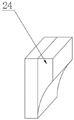
Fig. 5 is a schematic perspective view of the clamping block of the present invention.
The reference signs are: 1. a base; 2. fixing the rod; 3. a top plate; 4. a circular electric rail; 5. a track block; 6. a hydraulic lever; 7. a rotating shaft; 8. a partition plate; 9. positioning a rod; 10. positioning a groove; 11. positioning a plate; 12. polishing the bulges; 13. grinding the shell upwards; 14. lower grinding shell; 15. a stay bar; 16. an adjusting ring; 17. a screw; 18. a clamping block; 19. a threaded sleeve; 20. polishing the layer; 21. an electric slide rail; 22. a slider; 23. a three-jaw chuck; 24. and (4) clamping the block.
Detailed Description
The technical solutions in the embodiments of the present invention will be clearly and completely described below with reference to the drawings in the embodiments of the present invention, and it is obvious that the described embodiments are only a part of the embodiments of the present invention, and not all of the embodiments. All other embodiments, which can be derived by a person skilled in the art from the embodiments given herein without making any creative effort, shall fall within the protection scope of the present invention.
The burr removing device for processing the aluminum casting shown in the attached figures 1-5 comprises a base 1, wherein a fixed rod 2 is fixedly arranged at the top of the base 1, a top plate 3 is fixedly arranged at the top of the fixed rod 2, and a circular electric rail 4 is fixedly arranged at the bottom of the top plate 3;
4 bottoms of circular electronic track are equipped with track piece 5, the fixed hydraulic stem 6 that is equipped with in 5 bottoms of track piece, 6 output ends of hydraulic stem are equipped with the motor, motor output shaft is equipped with pivot 7, the fixed baffle 8 that is equipped with in 7 bottoms of pivot, the fixed mechanism that rubs off that is equipped with in 8 bottoms of baffle.
According to the figure 2, the grinding mechanism comprises a positioning rod 9, the positioning rod 9 is fixedly connected with a partition plate 8, a positioning groove 10 is arranged on the surface of the positioning rod 9, a positioning disc 11 is fixedly arranged on the outer side of the positioning rod 9, a grinding bulge 12 is fixedly arranged on the outer side of the positioning disc 11, a plurality of upper grinding shells 13 are hinged on the top of the outer side of the positioning disc 11, a plurality of lower grinding shells 14 are hinged on the bottom of the outer side of the positioning disc 11, supporting rods 15 are hinged on one sides of the upper grinding shells 13 and the lower grinding shells 14, one ends of the supporting rods 15 are hinged with an adjusting ring 16, the adjusting ring 16 is sleeved on the outer side of the positioning rod 9, a screw rod 17 is arranged inside the adjusting ring 16, a clamping block 18 is fixedly arranged at one end of the screw rod 17, a threaded sleeve 19 is arranged on the outer side of the screw rod 17, the threaded sleeve 19 penetrates through the adjusting ring 16 and is fixed with the adjusting ring 16, a button plate is fixedly arranged at one end of the screw rod 17, go up shell 13 and the shell 14 cross sectional shape of polishing down and all set up to the arc, go up shell 13 and the shell 14 outside of polishing down and all fix and be equipped with layer 20 of polishing, through wrench movement button board, the button board passes through screw rod 17 and drives fixture block 18 and extrude fixedly to constant head tank 10 inner wall to with the certain height in the present locating lever 9 outside of adjustable ring 16, thereby the flip angle of shell 13 and the shell 14 of polishing down in the indirect control.
In some embodiments, as shown in fig. 1 and 5, an electric slide rail 21 is fixedly arranged on the top of the base 1, a slide block 22 is arranged on the top of the electric slide rail 21, a placing table is fixedly arranged on the top of the slide block 22, a three-jaw chuck 23 is fixedly arranged on the top of the placing table, a clamping block 24 is welded on the top of the three-jaw chuck 23, and the cross section of the clamping block 24 is trapezoidal.
The working principle of the utility model is as follows: during the use, fix circular shape aluminium casting on three-jaw chuck 23, it is fixed with the card angle on three-jaw chuck 23, the cross sectional shape sets up to the grip block 24 of right angle ladder and can carry out the centre gripping to the annular of bottom fixedly, later drive the slider 22 through electronic slide rail 21 and promote to place the platform and carry out horizontal migration with the aluminium casting, later open hydraulic stem 6, hydraulic stem 6 drives the motor and goes up and down, later electric drive pivot 7 drives baffle 8 and grinds off the mechanism and to getting into the inboard position of aluminium casting, later promote adjustable ring 16, adjustable ring 16 drives upper polishing shell 13 and lower polishing shell 14 through vaulting pole 15 and overturns, later carry out the adaptation according to the inclination at aluminium casting edge with upper polishing shell 13 and the angle of lower polishing shell 14 and adjust, the protruding position of polishing of arch 12 that sets up is polished, when aluminium casting diameter is great, open circular electric track 4, circular electric track 4 drives the indirect drive of hydraulic stem 6 through track block 5 and grinds off the mechanism and carry out circular shape The orbit motion to enlarge the orbit scope of polishing, this structure can not only polish to inside, will go up polishing shell 13 simultaneously and polish shell 14 down and adjust into the wide-angle and carry out half the encirclement to the border position, thereby improve the angle of polishing, can carry out the grinding to it according to the unedged angle of aluminium casting, make the effect that can accomplish the integration and get rid of when carrying out the deckle edge to circular shape aluminium casting and get rid of.
The points to be finally explained are: first, in the description of the present application, it should be noted that, unless otherwise specified and limited, the terms "mounted," "connected," and "connected" should be understood broadly, and may be a mechanical connection or an electrical connection, or a communication between two elements, and may be a direct connection, and "upper," "lower," "left," and "right" are only used to indicate a relative positional relationship, and when the absolute position of the object to be described is changed, the relative positional relationship may be changed;
secondly, the method comprises the following steps: in the drawings of the disclosed embodiments of the utility model, only the structures related to the disclosed embodiments are referred to, other structures can refer to common designs, and the same embodiment and different embodiments of the utility model can be combined with each other without conflict;
and finally: the above description is only for the purpose of illustrating the preferred embodiments of the present invention and is not to be construed as limiting the utility model, and any modifications, equivalents, improvements and the like that are within the spirit and principle of the present invention are intended to be included in the scope of the present invention.
Claims (7)
1. The utility model provides a burr remove device is used in processing of aluminum casting, includes base (1), its characterized in that: a fixed rod (2) is fixedly arranged at the top of the base (1), a top plate (3) is fixedly arranged at the top of the fixed rod (2), and a circular electric track (4) is fixedly arranged at the bottom of the top plate (3);
circular electronic track (4) bottom is equipped with track piece (5), fixed hydraulic stem (6) that are equipped with in track piece (5) bottom, hydraulic stem (6) output is equipped with the motor, the motor output shaft is equipped with pivot (7), pivot (7) bottom is fixed and is equipped with baffle (8), baffle (8) bottom is fixed and is equipped with the mechanism that rubs off.
2. The apparatus of claim 1 for deburring aluminum castings, wherein: the grinding mechanism comprises a positioning rod (9), the positioning rod (9) is fixedly connected with a partition plate (8), a positioning groove (10) is formed in the surface of the positioning rod (9), a positioning disc (11) is fixedly arranged on the outer side of the positioning rod (9), a grinding bulge (12) is fixedly arranged on the outer side of the positioning disc (11), a plurality of upper grinding shells (13) are hinged to the top of the outer side of the positioning disc (11), and a plurality of lower grinding shells (14) are hinged to the bottom of the outer side of the positioning disc (11).
3. The apparatus of claim 2 for deburring aluminum castings, wherein: go up and polish shell (13) and polish shell (14) one side down and all articulate there is vaulting pole (15), vaulting pole (15) one end articulates there is adjustable ring (16), adjustable ring (16) cover is established in the locating lever (9) outside.
4. The apparatus of claim 3 for deburring aluminum castings, wherein: the utility model discloses a quick-witted, including adjustable ring (16), adjusting ring (16) inside is equipped with screw rod (17), screw rod (17) one end is fixed and is equipped with fixture block (18), the screw rod (17) outside is equipped with swivel nut (19), swivel nut (19) run through adjustable ring (16) and fixed with adjustable ring (16), screw rod (17) one end is fixed and is equipped with the button board.
5. The apparatus of claim 2 for deburring aluminum castings, wherein: the cross section shapes of the upper grinding shell (13) and the lower grinding shell (14) are arc-shaped, and grinding layers (20) are fixedly arranged on the outer sides of the upper grinding shell (13) and the lower grinding shell (14).
6. The apparatus of claim 1 for deburring aluminum castings, wherein: the base (1) top is fixed and is equipped with electronic slide rail (21), electronic slide rail (21) top is equipped with slider (22), the fixed platform of placing that is equipped with in slider (22) top.
7. The apparatus of claim 6 for deburring aluminum castings, wherein: the placing table top is fixedly provided with a three-jaw chuck (23), the top of the three-jaw chuck (23) is welded with a clamping block (24), and the cross section of the clamping block (24) is trapezoidal.
Priority Applications (1)
| Application Number | Priority Date | Filing Date | Title |
|---|---|---|---|
| CN202122995854.6U CN216265073U (en) | 2021-12-02 | 2021-12-02 | Burr removing device for aluminum casting machining |
Applications Claiming Priority (1)
| Application Number | Priority Date | Filing Date | Title |
|---|---|---|---|
| CN202122995854.6U CN216265073U (en) | 2021-12-02 | 2021-12-02 | Burr removing device for aluminum casting machining |
Publications (1)
| Publication Number | Publication Date |
|---|---|
| CN216265073U true CN216265073U (en) | 2022-04-12 |
Family
ID=81040552
Family Applications (1)
| Application Number | Title | Priority Date | Filing Date |
|---|---|---|---|
| CN202122995854.6U Active CN216265073U (en) | 2021-12-02 | 2021-12-02 | Burr removing device for aluminum casting machining |
Country Status (1)
| Country | Link |
|---|---|
| CN (1) | CN216265073U (en) |
-
2021
- 2021-12-02 CN CN202122995854.6U patent/CN216265073U/en active Active
Similar Documents
| Publication | Publication Date | Title |
|---|---|---|
| CN111571366A (en) | Surface polishing device for spherical casting | |
| CN112621993B (en) | Blank-making rolling equipment for ceramic production | |
| CN112171473A (en) | High-efficient two-sided equipment of polishing of polytypic nodular cast iron well lid | |
| CN210476482U (en) | Casting polishing positioning device | |
| CN216265073U (en) | Burr removing device for aluminum casting machining | |
| CN114260762A (en) | Efficient internal and external synchronous polishing equipment for circular castings | |
| CN211940284U (en) | Curved surface equipment of polishing | |
| CN218081951U (en) | High-efficient automatic rotatory hydraulic pressure foundry goods processing frock | |
| CN111974587A (en) | Coating auxiliary device for machining foam evaporative pattern capable of being adjusted in all directions | |
| CN216608278U (en) | Surface grinding device is used in metal parts processing | |
| CN217224926U (en) | Vibration material disk grinding device | |
| CN206997784U (en) | A kind of axle class turning all-in-one | |
| CN211805227U (en) | Psammitolite unhairing limit device | |
| CN218364087U (en) | Car door boundary beam decorative board processing positioner | |
| CN216940067U (en) | Burnishing device is used in bearing processing production | |
| CN218696777U (en) | Polishing device for inner side hole wall and chamfer of casting | |
| CN213917664U (en) | Burnishing machine is used in picture frame processing | |
| CN217942845U (en) | Cast aluminium end cover burr clearing device | |
| CN220217869U (en) | Multi-station plastic suction box die surface polishing device | |
| CN214559923U (en) | Precision polishing machine based on elastic controllable grinding tool | |
| CN219426726U (en) | Tire mold positioning device | |
| CN220312971U (en) | Polishing machine | |
| CN213765185U (en) | Casting part polishing device | |
| CN216608448U (en) | Polishing and grinding device for production of side plate die of automobile seat backrest | |
| CN217860396U (en) | Connecting rod bolt burr removing machine |
Legal Events
| Date | Code | Title | Description |
|---|---|---|---|
| GR01 | Patent grant | ||
| GR01 | Patent grant |