CN216247221U - Universal multi-connecting-rod type vertical tool for solid rocket engine - Google Patents
Universal multi-connecting-rod type vertical tool for solid rocket engine Download PDFInfo
- Publication number
- CN216247221U CN216247221U CN202122548998.7U CN202122548998U CN216247221U CN 216247221 U CN216247221 U CN 216247221U CN 202122548998 U CN202122548998 U CN 202122548998U CN 216247221 U CN216247221 U CN 216247221U
- Authority
- CN
- China
- Prior art keywords
- adapter plate
- pull rod
- segmental
- engine
- solid rocket
- Prior art date
- Legal status (The legal status is an assumption and is not a legal conclusion. Google has not performed a legal analysis and makes no representation as to the accuracy of the status listed.)
- Active
Links
Images


Landscapes
- Testing Of Engines (AREA)
Abstract
The utility model provides a vertical frock of general multi-link formula solid rocket engine, includes preceding fishplate bar (1), back keysets (8), base (9), preceding fishplate bar (1), back keysets (8) and base (9) correspond the setting from the top down, preceding fishplate bar (1) and back keysets (8) are the ring structure, connect through flexible pull rod device along the circumferencial direction between preceding fishplate bar (1) and the back keysets (8), back keysets (8) be connected with base (9). The axial working state of the engine can be truly simulated, and the engine has the advantages of adjustable length size, adjustable radial size, axial centering and the like; the axial mechanical environment requirement born by the more real simulation engine in working can be met.
Description
Technical Field
The utility model relates to a vertical tool of an engine, in particular to a vertical tool of a universal multi-connecting-rod type solid rocket engine, and belongs to the technical field of vibration and impact tests.
Background
The solid rocket engine is used as an engine of a rocket projectile, a missile and a sounding rocket and a boosting engine launched by a spacecraft, and bears various vibration and impact loads in the working process; therefore, the high reliability and strong environmental adaptability become the key of the quality characteristics of the solid rocket engine. The ground vibration and impact test is a main way for examining the environmental adaptability of the solid rocket engine, and can test whether the performance of the engine meets the requirements or not and expose the design defects of the engine of the type, thereby providing guidance for the optimization and improvement of the engine; in the vibration and impact test process, in order to simulate the mechanical environment borne by the engine in work more truly, the axial test is generally carried out by adopting a vertical tool.
At present, various aircrafts using solid rocket engines are more and more, and many models of aircrafts need to be subjected to identification tests and batch spot inspection tests; the traditional vertical vibration impact tool needs to repeatedly carry out a large number of machining tests according to engines of different models, so that the serious waste of machining materials and the waste of test sites are caused, and a lot of industrial wastes are generated. However, at present, no general vertical tool can solve the problems, and therefore, a more reasonable and efficient vertical vibration impact test tool needs to be designed urgently.
Disclosure of Invention
The utility model aims to provide a universal multi-connecting-rod type solid rocket engine vertical tool aiming at the problems in the prior art.
In order to achieve the purpose, the technical solution of the utility model is as follows: the utility model provides a vertical frock of general multi-link formula solid rocket engine, includes preceding adapter plate, back keysets, base, preceding adapter plate, back adapter plate and base correspond the setting from top to bottom, preceding adapter plate and back adapter plate are the ring structure, connect through flexible pull rod device along the circumferencial direction between preceding adapter plate and the back adapter plate, back adapter plate be connected with the base.
The telescopic pull rod device comprises a plurality of sections of segmental pull rods, adjacent segmental pull rods are connected through connecting threaded sleeves, the segmental pull rod connected with the front adapter plate is a first section of segmental pull rod, the upper end of the first section of segmental pull rod is inserted into the front adapter plate, the segmental pull rod connected with the rear adapter plate is a tail section of segmental pull rod, and the lower end of the tail section of segmental pull rod is inserted into the rear adapter plate.
T-shaped grooves are uniformly distributed in the circumferential direction on the front connecting plate, T-shaped stop blocks are embedded in the T-shaped grooves, and the front connecting plate and the T-shaped stop blocks are assembled into a whole through fixing bolts.
The anti-debonding structure is characterized in that an anti-debonding hole is formed in the working surface of the T-shaped stop block, and a PU (polyurethane) rubber pad is bonded to the anti-debonding hole.
Compared with the prior art, the utility model has the beneficial effects that:
the utility model can satisfy the axial working state of a real simulation engine and has the advantages of adjustable length size, adjustable radial size, axial centering and the like. The problems that vertical test tools need to be repeatedly processed, the test preparation period is long, the test efficiency is low, raw materials are wasted, the cost is increased and the like when engines of different models are subjected to axial vibration and impact tests are solved; the axial mechanical environment requirement born by the more real simulation engine in working can be met.
Drawings
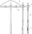
FIG. 1 is a schematic diagram of the present invention.
FIG. 2 is a schematic view of the connection between the front adapter plate and the articulated arm according to the present invention.
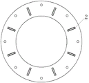
Fig. 3 is a schematic structural view of a front adapter plate in the present invention.
Fig. 4 is a schematic view of a segmented pull rod structure according to the present invention.
Fig. 5 is a schematic view of the structure of the coupling nut of the present invention.
FIG. 6 is a front view of the T-stop of the present invention.
Fig. 7 is a left side view of the T-shaped stop of the present invention.
Fig. 8 is a schematic structural view of a rear adapter plate according to the present invention.
Fig. 9 is a top view of the base of the present invention.
Figure 10 is a side view of the base of the present invention.
Fig. 11 is a bottom view of the base of the present invention.
Fig. 12 is a schematic diagram of the application of the present invention.
In the figure: the test bench comprises a front adapter plate 1, a T-shaped groove 2, a T-shaped stop block 3, a fixing bolt 4, a PU (polyurethane) rubber pad 5, a segmented pull rod 6, a connecting threaded sleeve 7, a rear adapter plate 8, a base 9 and a test bench 10.
Detailed Description
The utility model is described in further detail below with reference to the following description of the drawings and the detailed description.
Referring to fig. 1 to 12, a vertical tool for a universal multi-link solid rocket engine is characterized in that: comprises a front adapter plate 1, a rear adapter plate 8 and a base 9. The front adapter plate 1, the rear adapter plate 8 and the base 9 are correspondingly arranged from top to bottom, the front adapter plate 1 and the rear adapter plate 8 are both of a circular ring structure, the front adapter plate 1 and the rear adapter plate 8 are connected through a telescopic pull rod device in the circumferential direction, the rear adapter plate 8 is connected with the base 9, and the base 9 is connected with the test bed 10 for a vibration impact test.
Referring to fig. 1 to 12, the telescopic rod device includes a plurality of sectional rods 6, and adjacent sectional rods 6 are connected by a connecting screw sleeve 7; specifically, the connecting end of the segmented pull rod 6 and the connecting threaded sleeve 7 is inserted into the connecting threaded sleeve 7; the segmental pull rod 6 is provided with a clamping surface, so that the assembly is convenient. The length of the segmented pull rod 6 is a fixed value (500mm or 1000mm), the connecting threaded sleeve 7 is 30CrMnSi, the tool has the advantages of high strength and high toughness, and the adjustment of the length size of the tool in use is realized by selecting the number and the specification of the segmented pull rod 6 and changing the connecting length of the segmented pull rod 6 and the connecting threaded sleeve 7. The upper end of a section pull rod 6 connected with the front adapter plate 1 is inserted on the front adapter plate 1, and the lower end of a section pull rod 6 connected with the rear adapter plate 8 is inserted on the rear adapter plate 8.
Referring to fig. 1 to 12, T-shaped grooves 2 are uniformly distributed on the front adapter plate 1 along the circumferential direction, T-shaped stop blocks 3 are embedded in the T-shaped grooves 2, the T-shaped grooves 2 prevent the T-shaped stop blocks 3 from sliding left and right, and the T-shaped stop blocks 3 are more firmly fixed on the front adapter plate 1; the front rotary joint plate 1 and the T-shaped stop block 3 are assembled into a whole through a fixing bolt 4, the fixing bolt 4 is a 12.9-level high-strength bolt, and the using diameter is adjusted by changing the position of the T-shaped stop block 3. Further, 3 working faces of T type chock be provided with the anticreep hole that glues, the anticreep glue the hole on bond PU polyurethane rubber pad 5, PU polyurethane rubber pad 5 and the engine direct contact on 3 working faces of T type chock prevent to damage engine surface coating, guarantee simultaneously that working face hardness is enough, increase frictional force.
Fig. 1 to 12 show that, in the test, an engine is arranged between a front adapter plate 1 and a rear adapter plate 8, the position of a T-shaped stop block 3 is adjusted according to the diameter of the engine, and the T-shaped stop block 3 is fixed through a fixing bolt 4; the number and the specification of the section pull rods 6 are selected according to the distance between the front end and the rear end of the engine, the engine is horizontally placed and then connected with the front adapter plate 1 and the rear adapter plate 8, and the front adapter plate 1 and the rear adapter plate 8 are tensioned by using the assembled telescopic pull rod device. Then the engine is turned over to be vertical, and the rear adapter plate 8 is fixedly butted with the base 9. The multi-section sectional pull rod 6 and the connecting threaded sleeve 7 are assembled, so that different use lengths can be adjusted, and the test preparation time and the test cost are greatly reduced; the problem of different model engine length is solved, the problem of processing test pull rod many times has basically been avoided to can used repeatedly many times. The position of the T-shaped stop block 3 can be adjusted to meet the requirement that an engine in a certain diameter range is tested by using the tool, (for example, the diameter of the engine is 800-1200 mm), the radial size of the engine can be adjusted, the engine is axially centered, the axial eccentricity of the engine is prevented, and meanwhile, the adapter plate is convenient to mount; the processing requirement of the adapter plate can be reduced to a certain extent, the test cost is saved, and the test requirement can be met. The mounted engine and the tool are fixed on the test bed 10, the test bed 10 is driven to start vibration, impact and other tests, and the steps are repeated, so that axial tests of engines of different models can be performed. In conclusion, the tool solves the problems that the test tool needs to be repeatedly processed, the test efficiency is low, the waste of processing materials is caused, the cost is increased and the like when engines of different models are subjected to axial vibration and impact tests through the variable stop diameter and multi-connecting rod type design; the axial vibration impact test of the engine with different lengths and different diameters in a certain range can be carried out, so that the problems of test cost increase and raw material loss caused by different diameters, different lengths and the like of the engine are solved, the aim of improving the test efficiency is achieved, the axial vibration impact test device can be widely applied to the field of vibration and impact tests of the engine, the test preparation time is greatly shortened, and the tool utilization rate and the test capability are improved.
The foregoing is a more detailed description of the utility model in connection with specific preferred embodiments and it is not intended that the utility model be limited to these specific details. For those skilled in the art to which the utility model relates, several simple deductions or substitutions may be made without departing from the spirit of the utility model, and the above-mentioned structures should be considered as belonging to the protection scope of the utility model.
Claims (4)
1. The utility model provides a vertical frock of general multi-link formula solid rocket engine which characterized in that: the front adapter plate (1), the rear adapter plate (8) and the base (9) are arranged correspondingly from top to bottom, the front adapter plate (1) and the rear adapter plate (8) are both of a circular ring structure, the front adapter plate (1) and the rear adapter plate (8) are connected through a telescopic pull rod device in the circumferential direction, and the rear adapter plate (8) is connected with the base (9).
2. The vertical tool for the universal multi-link solid rocket engine according to claim 1, wherein: the telescopic pull rod device comprises a plurality of sections of segmental pull rods (6), adjacent segmental pull rods (6) are connected through connecting threaded sleeves (7), the segmental pull rod (6) connected with a front adapter plate (1) is a first-section segmental pull rod (6), the upper end of the first-section segmental pull rod (6) is inserted into the front adapter plate (1), the segmental pull rod (6) connected with a rear adapter plate (8) is a tail-section segmental pull rod (6), and the lower end of the tail-section segmental pull rod (6) is inserted into the rear adapter plate (8).
3. The vertical tool for the universal multi-link solid rocket engine according to claim 1, wherein: the front rotary connecting plate is characterized in that T-shaped grooves (2) are uniformly distributed in the circumferential direction on the front rotary connecting plate (1), T-shaped stop blocks (3) are embedded in the T-shaped grooves (2), and the front rotary connecting plate (1) and the T-shaped stop blocks (3) are assembled into a whole through fixing bolts (4).
4. The vertical tool for the universal multi-link solid rocket engine according to claim 3, wherein: the working surface of the T-shaped stop block (3) is provided with an anti-debonding hole, and a PU polyurethane rubber pad (5) is bonded on the anti-debonding hole.
Priority Applications (1)
| Application Number | Priority Date | Filing Date | Title |
|---|---|---|---|
| CN202122548998.7U CN216247221U (en) | 2021-10-22 | 2021-10-22 | Universal multi-connecting-rod type vertical tool for solid rocket engine |
Applications Claiming Priority (1)
| Application Number | Priority Date | Filing Date | Title |
|---|---|---|---|
| CN202122548998.7U CN216247221U (en) | 2021-10-22 | 2021-10-22 | Universal multi-connecting-rod type vertical tool for solid rocket engine |
Publications (1)
| Publication Number | Publication Date |
|---|---|
| CN216247221U true CN216247221U (en) | 2022-04-08 |
Family
ID=80993160
Family Applications (1)
| Application Number | Title | Priority Date | Filing Date |
|---|---|---|---|
| CN202122548998.7U Active CN216247221U (en) | 2021-10-22 | 2021-10-22 | Universal multi-connecting-rod type vertical tool for solid rocket engine |
Country Status (1)
| Country | Link |
|---|---|
| CN (1) | CN216247221U (en) |
-
2021
- 2021-10-22 CN CN202122548998.7U patent/CN216247221U/en active Active
Similar Documents
| Publication | Publication Date | Title |
|---|---|---|
| CN110497216B (en) | Synchronous self-locking type pneumatic self-adaptive clamp for processing annular thin-walled part | |
| CN103495753B (en) | Novel thin film chuck | |
| CN211540092U (en) | Pipeline positioning butt joint device | |
| CN216247221U (en) | Universal multi-connecting-rod type vertical tool for solid rocket engine | |
| CN110480373B (en) | Spring jacket mechanism for rapidly installing shaft parts | |
| CN114001963A (en) | Universal multi-connecting-rod type vertical tool for solid rocket engine | |
| CN105458981A (en) | Self-centering clamping device for oil cylinder assembly | |
| CN117226568A (en) | Clamp conversion structure, clamp and clamp replacement method for disc part machining | |
| CN107336057B (en) | Piston ring mounting device and method | |
| CN201913489U (en) | Clamp system for connection and processing of pump wheel assembly | |
| CN212168997U (en) | Floating type three-jaw chuck convenient for clamping irregular cylindrical structure | |
| CN103978240A (en) | Machine tool clamp and machine tool using machine tool clamp | |
| CN215144817U (en) | Automatic lathe machining clamp for thin-wall part | |
| CN110605602B (en) | Special machine for turning shaft end faces | |
| CN211072755U (en) | Special machine for turning shaft end faces | |
| CN113523850A (en) | Clamp and clamping method for non-revolving body conical part | |
| CN211220241U (en) | Pneumatic clamping device for finishing | |
| CN210060464U (en) | Pump body boring grab | |
| CN204584760U (en) | Motor case vehicle clamper | |
| CN112264652A (en) | Gear milling machining tool for diesel engine connecting rod | |
| CN203817428U (en) | Machine tool clamp and machine tool using same | |
| CN219053684U (en) | Numerical control car hydraulic pressure frock clamp | |
| CN219561457U (en) | Internal support clamp for fixing chuck | |
| CN218947364U (en) | Positioning tool for grinding outer circle of thin barrel part | |
| CN114211012B (en) | Cylinder barrel turning expansion type fixing jig and processing method thereof |
Legal Events
| Date | Code | Title | Description |
|---|---|---|---|
| GR01 | Patent grant | ||
| GR01 | Patent grant |