CN216223621U - Smoke dust treatment equipment for steel plant - Google Patents
Smoke dust treatment equipment for steel plant Download PDFInfo
- Publication number
- CN216223621U CN216223621U CN202122775786.2U CN202122775786U CN216223621U CN 216223621 U CN216223621 U CN 216223621U CN 202122775786 U CN202122775786 U CN 202122775786U CN 216223621 U CN216223621 U CN 216223621U
- Authority
- CN
- China
- Prior art keywords
- dry
- pipe
- filter chamber
- filtering chamber
- water
- Prior art date
- Legal status (The legal status is an assumption and is not a legal conclusion. Google has not performed a legal analysis and makes no representation as to the accuracy of the status listed.)
- Active
Links
Images


Landscapes
- Filtering Of Dispersed Particles In Gases (AREA)
- Separation Of Particles Using Liquids (AREA)
Abstract
The utility model discloses smoke dust treatment equipment for a steel plant, which comprises a box body, wherein a water filtering chamber and a dry filtering chamber are arranged in the box body, an air outlet cover is arranged on the side wall of the water filtering chamber, an air inlet cover is arranged on the side wall of the dry filtering chamber, a rotating pipe which is rotatably connected with the dry filtering chamber is arranged at the top of the dry filtering chamber in a penetrating manner, one end, positioned in the dry filtering chamber, of the rotating pipe is connected with a filtering screen cylinder, a brush rod which is in contact with the filtering screen cylinder is fixed on the inner top wall of the dry filtering chamber, the upper end of the rotating pipe is connected with an air distribution pipe through a rotary joint, one end, far away from the rotary joint, of the air distribution pipe penetrates through the top of the water filtering chamber and extends into the water filtering chamber, a stirrer is rotatably connected with the inner top of the water filtering chamber, and a driving mechanism which is connected with the rotating pipe and the stirrer is arranged at the top of the box body. The utility model carries out dry filtration and water filtration on the smoke dust in sequence, effectively realizes the purification effect on the smoke dust and ensures the health of operators in the operation process.
Description
Technical Field
The utility model relates to the technical field of smoke treatment of steel plants, in particular to smoke treatment equipment for steel plants.
Background
In the production and processing of steel plant, can produce a large amount of smoke and dust, and contain a large amount of hazardous substances in the smoke and dust, these hazardous substances seriously harm the health of the workman of long-term work, consequently need use smoke and dust treatment facility, handle the smoke and dust, but current smoke and dust treatment facility can deposit more dust on its filter screen after long-time the use usually, and then the ventilation efficiency who influences the dirt filtration, influence the filter effect, and current dirt filtering mode is comparatively single, and the smoke and dust treatment effect is not good enough.
SUMMERY OF THE UTILITY MODEL
The utility model aims to solve the defects in the prior art and provides smoke dust treatment equipment for a steel plant.
In order to achieve the purpose, the utility model adopts the following technical scheme:
the utility model provides a smoke and dust treatment facility that steel mill used, the power distribution box comprises a box body, the inside of box is equipped with water filter chamber, dry filter chamber, be equipped with out the gas hood on the lateral wall of water filter chamber, be equipped with the cover that admits air on the lateral wall of dry filter chamber, the top of dry filter chamber is run through and is equipped with the runner pipe of being connected rather than rotating, the one end that the runner pipe is located dry filter chamber is connected with a filter screen section of thick bamboo, be fixed with the brush-holder stud with filter screen section of thick bamboo contact on the interior roof of dry filter chamber, the upper end of runner pipe is connected with the gas distribution pipe through rotary joint, the one end that rotary joint was kept away from to the gas distribution pipe runs through the top of water filter chamber and extends to the inside of water filter chamber, the interior top of water filter chamber is rotated and is connected with the agitator, the top of box is equipped with the actuating mechanism who is connected with runner pipe, agitator.
As a further improvement of the utility model, the driving mechanism comprises a motor arranged at the top of the box body, an output shaft of the motor faces upwards and is fixed with a second gear, a first gear is fixedly sleeved on the rotating pipe, a third gear is fixed at the top of the stirrer, and the first gear and the third gear are in transmission connection with the second gear through a gear belt.
As a further improvement of the utility model, the bottom of the water filter chamber is connected with a drain pipe, the drain pipe is provided with a valve, and the top of the water filter chamber is connected with a water injection pipe.
As a further improvement of the utility model, the bottom of the dry filtering chamber is connected with a dust exhaust pipe, the bottom of the dust exhaust pipe is in threaded connection with a sealing cover, the upper end of the sealing cover is uniformly provided with magnetic rods, and the magnetic rods are sleeved with rubber sleeves.
As a further improvement of the utility model, the inner bottom walls of the water filtering chamber and the dry filtering chamber are both in a slope structure.
As a further improvement of the utility model, the four corners of the bottom of the box body are provided with moving wheels.
The utility model has the beneficial effects that:
through setting up runner pipe, filter screen section of thick bamboo, brush-holder stud, the drive runner pipe rotates and drives filter screen section of thick bamboo and rotate, produces relative rotation between filter screen section of thick bamboo and the brush-holder stud, can clear up filter screen section of thick bamboo's surface through the brush-holder stud, avoids the too much long-pending surface of attaching at filter screen section of thick bamboo of dust, and then keeps filter screen section of thick bamboo better filtration performance of ventilating, guarantees higher filtration efficiency.
Through setting up dust exhaust pipe, closing cap, bar magnet, rubber sleeve, can make the dust discharge clearance that accumulated when filtering in the dry filter chamber through opening the closing cap, can adsorb the collection to iron fillings in the dust through the bar magnet, through taking off the rubber sleeve, can be with under the convenient clearance of iron fillings, do benefit to the recycle of resource.
The utility model carries out dry filtration and water filtration on the smoke dust in sequence, effectively realizes the purification effect on the smoke dust and ensures the health of operators in the operation process.
Drawings
FIG. 1 is a schematic structural view of a smoke and dust treatment facility for a steel plant according to the present invention;
FIG. 2 is a schematic structural diagram of a cover and a magnetic rod of the smoke dust treatment equipment for the steel plant;
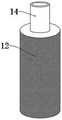
FIG. 3 is a schematic structural diagram of a rotary pipe and a filter screen cylinder of the smoke dust treatment equipment for the steel plant.
In the figure: the device comprises a box body 1, a moving wheel 2, a water discharge pipe 3, a valve 4, a water filter chamber 5, a dry filter chamber 6, a dust discharge pipe 7, a seal cover 8, a magnetic rod 9, a rubber sleeve 10, a brush rod 11, a filter screen cylinder 12, an air inlet cover 13, a rotating pipe 14, a first gear 15, a gear belt 16, a rotary joint 17, an air distribution pipe 18, a second gear 19, a motor 20, a third gear 21, a stirrer 22, an air outlet cover 23 and a water injection pipe 24.
Detailed Description
The technical solutions in the embodiments of the present invention will be clearly and completely described below with reference to the drawings in the embodiments of the present invention, and it is obvious that the described embodiments are only a part of the embodiments of the present invention, and not all of the embodiments.
Referring to fig. 1-3, a smoke dust treatment device for a steel plant comprises a box body 1, wherein moving wheels 2 are arranged at four corners of the bottom of the box body 1, so that the device can be conveniently transferred and moved, a water filtering chamber 5 and a dry filtering chamber 6 are arranged in the box body 1, an air outlet cover 23 is arranged on the side wall of the water filtering chamber 5, an air inlet cover 13 is arranged on the side wall of the dry filtering chamber 6, a rotating pipe 14 rotatably connected with the top of the dry filtering chamber 6 is arranged in a penetrating manner at the top of the dry filtering chamber 6, a filtering net cylinder 12 is connected with one end of the rotating pipe 14 positioned in the dry filtering chamber 6, a brush rod 11 in contact with the filtering net cylinder 12 is fixed on the inner top wall of the dry filtering chamber 6, the brush rod 11 is of an L-shaped structure, brush bristles are arranged on the side wall of the brush rod 11 and are in contact with the outer surface of the filtering net cylinder 12, an air distribution pipe 18 is connected with the upper end of the rotating joint 17, one end of the air distribution pipe 18 far away from the rotating joint 17 penetrates through the top of the water filtering chamber 5 and extends to the inside of the water filtering chamber 5, the interior top of water filter chamber 5 rotates and is connected with agitator 22, and the upper end of agitator 22 runs through the top of water filter chamber 5 and rotates with the top of water filter chamber 5 to be connected, and the top of box 1 is equipped with the actuating mechanism who is connected with rotary pipe 14, agitator 22.
In the utility model, the driving mechanism comprises a motor 20 arranged at the top of the box body 1, an output shaft of the motor 20 faces upwards and is fixed with a second gear 19, a rotating pipe 14 is fixedly sleeved with a first gear 15, a top of a stirrer 22 is fixed with a third gear 21, and the first gear 15 and the third gear 21 are in transmission connection with the second gear 19 through a gear belt 16.
The bottom of water filter chamber 5 is connected with drain pipe 3, is equipped with valve 4 on drain pipe 3, opens valve 4 and can make the waste water discharge in the water filter chamber 5, and the top of water filter chamber 5 is connected with water injection pipe 24, can conveniently add water to the interior interpolation of water filter chamber 5 through water injection pipe 24.
The bottom of dry filter chamber 6 is connected with dust exhaust pipe 7, the bottom threaded connection of dust exhaust pipe 7 has closing cap 8, closing cap 8's upper end evenly is equipped with bar magnet 9, the cover is equipped with rubber sleeve 10 on the bar magnet 9, the accessible is opened closing cap 8 and can be so that accumulated dust that attaches when filtering in the dry filter chamber 6 is discharged the clearance, can have thoughtlessly iron fillings in the smoke and dust of steel and iron works, accessible bar magnet 9 can adsorb the collection to iron fillings in the dust, through taking off rubber sleeve 10, can be with under the convenient clearance of iron fillings, do benefit to the recycle of resource.
The inner bottom walls of the water filtering chamber 5 and the dry filtering chamber 6 are both in an inclined plane structure, so that dust and waste water can be discharged conveniently.
When the smoke dust filter is used, smoke dust to be treated enters the dry filtering chamber 6 through the air inlet cover 13, the smoke dust is filtered through the filtering screen cylinder 12, the filtered smoke gas enters the water filtering chamber 5 through the air distribution pipe 18, further filtering is achieved through water filtering, the motor 20 is started to drive the second gear 19 to rotate, the first gear 15 and the third gear 21 are driven to rotate through the gear belt 16, the rotating pipe 14 can be driven to rotate, the filtering screen cylinder 12 is driven to rotate, the surface of the filtering screen cylinder 12 can be cleaned through the brush rod 11 through relative rotation between the filtering screen cylinder 12 and the brush rod 11, excessive dust is prevented from being attached to the surface of the filtering screen cylinder 12, the good ventilation and filtering performance of the filtering screen cylinder 12 is kept, the stirrer 22 is driven to rotate to stir water in the water filtering chamber 5, the filtering effect is improved, and filtered and purified gas is discharged through the air outlet cover 23.
The above description is only for the preferred embodiment of the present invention, but the scope of the present invention is not limited thereto, and any person skilled in the art should be considered to be within the technical scope of the present invention, and equivalent alternatives or modifications according to the technical solution of the present invention and the inventive concept thereof should be covered by the scope of the present invention.
Claims (8)
1. The smoke dust treatment equipment for the steel plant is characterized by comprising a box body (1), wherein a water filter chamber (5) and a dry filter chamber (6) are arranged inside the box body (1), an air outlet cover (23) is arranged on the side wall of the water filter chamber (5), an air inlet cover (13) is arranged on the side wall of the dry filter chamber (6), a rotary pipe (14) in rotating connection with the dry filter chamber is arranged at the top of the dry filter chamber (6) in a penetrating mode, one end, located in the dry filter chamber (6), of the rotary pipe (14) is connected with a filter screen cylinder (12), a brush rod (11) in contact with the filter screen cylinder (12) is fixed on the inner top wall of the dry filter chamber (6), the upper end of the rotary pipe (14) is connected with an air distribution pipe (18) through a rotary joint (17), one end, far away from the rotary joint (17), of the air distribution pipe (18) penetrates through the top of the water filter chamber (5) and extends to the inside of the water filter chamber (5), the water filter is characterized in that a stirrer (22) is rotatably connected to the inner top of the water filtering chamber (5), and a driving mechanism connected with the rotating pipe (14) and the stirrer (22) is arranged at the top of the box body (1).
2. The fume treatment equipment for the steel plant according to claim 1, characterized in that said driving mechanism comprises a motor (20) installed on the top of the box body (1), the output shaft of said motor (20) is upward and fixed with a second gear (19), said rotating pipe (14) is fixed with a first gear (15), the top of said agitator (22) is fixed with a third gear (21), said first gear (15) and said third gear (21) are in transmission connection with said second gear (19) through a gear belt (16).
3. A flue dust treatment plant for steel plants according to claim 1, characterized in that the bottom of the water filter chamber (5) is connected with a drain pipe (3), and the top of the water filter chamber (5) is connected with a water injection pipe (24).
4. A flue dust treatment plant for steel plants according to claim 3, characterized in that the drain pipe (3) is provided with a valve (4).
5. The dust treatment equipment for steel plants according to claim 1, characterized in that the bottom of the dry filtering chamber (6) is connected with a dust exhaust pipe (7), and the bottom of the dust exhaust pipe (7) is connected with a sealing cover (8) by screw thread.
6. The dust treatment equipment for steel factories according to claim 5, wherein the upper end of the sealing cover (8) is uniformly provided with magnetic bars (9), and the magnetic bars (9) are sleeved with rubber sleeves (10).
7. The fume treatment plant for steel and iron plants according to claim 1, characterized in that the inner bottom walls of said water filtering chamber (5) and said dry filtering chamber (6) are of a slope structure.
8. A fume treatment plant for steel plants according to claim 1, characterized in that the four corners of the bottom of said box (1) are provided with mobile wheels (2).
Priority Applications (1)
| Application Number | Priority Date | Filing Date | Title |
|---|---|---|---|
| CN202122775786.2U CN216223621U (en) | 2021-11-14 | 2021-11-14 | Smoke dust treatment equipment for steel plant |
Applications Claiming Priority (1)
| Application Number | Priority Date | Filing Date | Title |
|---|---|---|---|
| CN202122775786.2U CN216223621U (en) | 2021-11-14 | 2021-11-14 | Smoke dust treatment equipment for steel plant |
Publications (1)
| Publication Number | Publication Date |
|---|---|
| CN216223621U true CN216223621U (en) | 2022-04-08 |
Family
ID=80995468
Family Applications (1)
| Application Number | Title | Priority Date | Filing Date |
|---|---|---|---|
| CN202122775786.2U Active CN216223621U (en) | 2021-11-14 | 2021-11-14 | Smoke dust treatment equipment for steel plant |
Country Status (1)
| Country | Link |
|---|---|
| CN (1) | CN216223621U (en) |
-
2021
- 2021-11-14 CN CN202122775786.2U patent/CN216223621U/en active Active
Similar Documents
| Publication | Publication Date | Title |
|---|---|---|
| CN216223621U (en) | Smoke dust treatment equipment for steel plant | |
| CN213771369U (en) | High-performance rotary type grating machine | |
| CN218249127U (en) | Pollutant discharge purification device for chemical industry | |
| CN215842259U (en) | A dust treatment device for production and processing workshop | |
| CN215742669U (en) | Soil gas phase extraction tail gas treatment system | |
| CN213314059U (en) | Dust and waste gas treatment device | |
| CN212091107U (en) | Filter equipment for sewage treatment | |
| CN213134113U (en) | Dust collector is used in production of plastic-steel door and window | |
| CN210645575U (en) | Industrial waste gas handles and uses filtration purification device | |
| CN210545362U (en) | Raw materials reducing mechanism that production pottery was used | |
| CN213141970U (en) | Pomegranate wine preparation cleaning equipment | |
| CN220142943U (en) | Industrial environment-friendly dust treatment equipment | |
| CN215712144U (en) | Underground water pollutant purification device | |
| CN217961480U (en) | Environment-friendly energy-saving industrial wastewater treatment equipment | |
| CN215026644U (en) | Rotary disc filter for sewage treatment | |
| CN209493393U (en) | A kind of industrial wastewater collection device | |
| CN217512462U (en) | Waste smoke treatment device for animal fat extraction | |
| CN218107107U (en) | Waste gas treatment equipment for industrial production | |
| CN220926353U (en) | Circulating sand removing device | |
| CN214513342U (en) | Novel washing that water-reducing agent processing waste gas was used device | |
| CN214159140U (en) | Intelligent spraying treatment device for waste gas treatment | |
| CN221015110U (en) | Tail gas purifying equipment | |
| CN214182003U (en) | Chemical industry sewage filtration equipment convenient to clearance | |
| CN213492407U (en) | Sewage treatment equipment | |
| CN213699292U (en) | Compound exhaust-gas treatment machine |
Legal Events
| Date | Code | Title | Description |
|---|---|---|---|
| GR01 | Patent grant | ||
| GR01 | Patent grant |