CN216220675U - Desk and chair for noon break - Google Patents
Desk and chair for noon break Download PDFInfo
- Publication number
- CN216220675U CN216220675U CN202122430666.9U CN202122430666U CN216220675U CN 216220675 U CN216220675 U CN 216220675U CN 202122430666 U CN202122430666 U CN 202122430666U CN 216220675 U CN216220675 U CN 216220675U
- Authority
- CN
- China
- Prior art keywords
- plate
- connecting plate
- desk
- chair
- seat
- Prior art date
- Legal status (The legal status is an assumption and is not a legal conclusion. Google has not performed a legal analysis and makes no representation as to the accuracy of the status listed.)
- Active
Links
Images


Landscapes
- Combinations Of Kitchen Furniture (AREA)
Abstract
The utility model relates to a desk and chair capable of being used for noon break, belonging to the field of desk and chair, comprising a chair, wherein the chair comprises a support, a seat plate and a backrest, the seat plate and the backrest are arranged on the support, the backrest comprises a connecting plate and an adjusting plate which are mutually attached, the adjusting plate is arranged on the front surface of the connecting plate in an up-and-down position-adjustable manner through a sliding adjusting assembly, and the back surface of the connecting plate is arranged on the support in a backward-rotatable manner through a rotating adjusting assembly. The length of the backrest can be increased by arranging the adjusting plate on the opposite connecting plate, so that after the backrest is laid down by rotating the adjusting assembly, the backrest with enough length can well support the head of a student, therefore, the utility model can be used for noon break of primary and secondary school students in classrooms, and meanwhile, the comfort level of noon break of the primary and secondary school students can be improved.
Description
Technical Field
The utility model relates to the field of desk and chair, in particular to a desk and chair for noon break.
Background
Afternoon nap is essential for teenagers, but due to the limitation of the existing conditions, most middle and primary schools cannot provide proper afternoon nap facilities for students, most middle and primary school students can only lie prone on a desk to sleep in the noon under the existing conditions, and can have a little low-quality rest, but in the long run, the students are slightly sore in the waist and back, the learning state in the afternoon is affected, the backs of the students bow, the cervical vertebrae deform, and the physical health of the students is seriously affected.
To cope with this situation, many desk and chairs having a nap function have been developed, and students can half lie on the chair for lunch break by putting the back of the chair down backward. However, due to the limitation of the use scene of the desk and chair, the space of the classroom is insufficient when the desk and chair is used once, and the backrest of the chair cannot be designed too high, so that the backrest is difficult to support the head of the student after the backrest is laid down, and the problem of noon break of the student cannot be thoroughly solved.
SUMMERY OF THE UTILITY MODEL
Therefore, it is necessary to provide a desk and chair for noon break, which includes a seat, the seat includes a support, a seat plate and a backrest, the seat plate and the backrest are disposed on the support, the backrest includes a connecting plate and an adjusting plate, the connecting plate and the adjusting plate are disposed on the front surface of the connecting plate, the adjusting plate is disposed on the back surface of the connecting plate, and the adjusting plate is rotatable backward on the support.
Preferably, the lower extreme of regulating plate is provided with the inserted sheet, the seat corresponds the inserted sheet has seted up the socket, the inserted sheet is inserted and is located in the socket.
Preferably, the sliding adjustment assembly comprises a convex strip group arranged on the back of the adjustment plate, the convex strip group comprises a plurality of convex strips which are arranged up and down and are parallel to each other, the convex strips are arranged at equal intervals, a limit groove is formed between every two adjacent convex strips, the connecting plate is provided with a containing groove corresponding to the convex strip group and used for containing the convex strip group, the upper end of the containing groove is provided with a window penetrating through the connecting plate, an elastic plate is arranged in the window, the top end of the elastic plate is provided with a limit strip corresponding to the limit groove, the limit strip is embedded in the limit groove, the back of the connecting plate is rotatably provided with a rotary drum corresponding to the top end of the elastic plate, the circumferential surface of the rotary drum faces one end of the elastic plate and is provided with a convex strip, and the convex strip faces one side face of the elastic plate and is attached to the back of the elastic plate, and the surface of the rotary drum is also fixedly provided with a pinch plate.
Preferably, the connecting plate has been seted up along upper and lower direction and has been run through the spout of connecting plate, the regulating plate corresponds the spout is provided with the slider, slider slidable ground set up in the spout, just the slider is kept away from the fixed slide that is provided with in one side of regulating plate, slide slidable ground laminate in the back setting of connecting plate.
Preferably, the back of regulating plate corresponds the both sides of connecting plate are provided with first blend stop, first blend stop laminating the edge setting of connecting plate, just first blend stop is kept away from the one end of regulating plate is the fixed first clamp plate that is provided with still, first clamp plate laminating the back setting of connecting plate.
Preferably, the back of regulating plate corresponds the top of connecting plate is provided with the second blend stop, the laminating of second blend stop the edge setting of connecting plate, just the second blend stop is kept away from the one end of regulating plate is the fixed second clamp plate that is provided with still, the laminating of second clamp plate the back setting of connecting plate.
Preferably, the rotation adjusting assembly comprises mounting seats arranged on two sides of the back surface of the connecting plate, the bracket is provided with connecting seats corresponding to the mounting seats, and the connecting seats are positioned on the outer sides of the corresponding mounting seats; the mounting seat is provided with a slot corresponding to the connecting seat corresponding to the mounting seat, an arc-shaped limiting piece which is the same as the slot in center line is arranged in the slot, the connecting seat is provided with a cylindrical inserting column corresponding to the slot, the inserting column is rotatably inserted in the slot, the connecting seat is slidably abutted against the mounting seat, the inserting column corresponds to the arc-shaped limiting piece and is provided with an arc-shaped limiting groove which is the same as the inserting column in center line, the arc-shaped limiting piece is inserted in the arc-shaped limiting groove, and the central angle of the arc-shaped limiting piece is smaller than that of the arc-shaped limiting groove.
Preferably, the top end of the adjusting plate extends out of the top end of the connecting plate, and the top end part of the adjusting plate extending out of the connecting plate is provided with a handle hole penetrating through the adjusting plate.
Preferably, the support comprises an installation frame for installing the seat plate and the backrest and a support frame for supporting the installation frame, and the installation frame is arranged on the support frame in a liftable manner.
Preferably, the desk comprises support legs and a storage box arranged at the top ends of the support legs, and support pads are arranged on the support legs.
The principle and effect of the present invention will be further explained by combining the above technical scheme and the accompanying drawings:
1. the length of the backrest can be increased by lifting the adjusting plate relative to the connecting plate, so that after the backrest is laid down by rotating the adjusting assembly, the backrest with enough length can well support the head of a student.
2. The height of the seat plate can be adjusted, so that the chair can be suitable for students with different heights.
Drawings
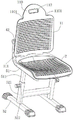
FIG. 1 is a first schematic structural view of a chair according to an embodiment of the present invention;
FIG. 2 is a second schematic structural view of a seat according to an embodiment of the present invention;
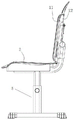
FIG. 3 is a schematic right-view structural diagram of a seat according to an embodiment of the present invention;
FIG. 4 is a schematic view of a seat according to an embodiment of the present invention in a partial cross-section;
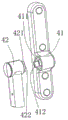
FIG. 5 is a schematic view of a fitting structure of the connecting seat and the mounting seat according to the embodiment of the present invention;
FIG. 6 is a schematic view of a seat back of the chair rotated backward in accordance with an embodiment of the present invention;
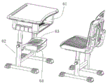
FIG. 7 is a schematic view of a structure of a chair and a desk according to an embodiment of the present invention;
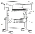
fig. 8 is a schematic structural view of a desk according to an embodiment of the utility model.
Description of reference numerals:
11-adjusting plate, 110 headrest part, 1101-groove, 111-inserting piece, 112-handle hole, 113-first blocking strip, 114-first pressing plate, 115-second blocking strip, 116-second pressing plate, 117-sliding plate, 118-raised strip, 119-limiting groove, 12-connecting plate, 121-sliding groove, 122-windowing, 123-elastic plate, 124-limiting strip, 2-seat plate, 31-rotating cylinder, 32-pressing strip, 33-buckling plate, 41-mounting seat, 411-slot, 412-arc limiting piece, 42-connecting seat, 421-inserting column, 422-arc limiting groove, 5-bracket, 51-mounting seat, 511-inserting rod, 52-supporting frame, 521-inserting column, 522-fastening screw rod, 61-storage box, 62-support leg, 63-support pad, 64-storage box, 651-mounting rod, 652-connecting rod, 66-mounting portion, 661-adjusting bolt.
Detailed Description
For the convenience of understanding of those skilled in the art, the present invention will be described in further detail below with reference to the accompanying drawings and examples:
in the description, all terms of directions such as front, back, left, right, up and down refer to fig. 1.
Referring to fig. 1-7, a desk and chair for noon break comprises a chair, wherein the chair comprises a support 5, a seat 2 and a backrest, the seat 2 and the backrest are arranged on the support 5, the backrest comprises a connecting plate 12 and an adjusting plate 11 which are attached to each other, the adjusting plate 11 is arranged on the front surface of the connecting plate 12 in a vertically adjustable manner through a sliding adjusting assembly, and the back surface of the connecting plate 12 is arranged on the support 5 in a rearward rotatable manner through a rotating adjusting assembly.
According to the utility model, the backrest comprises the connecting plate 12 and the adjusting plate 11 which are mutually attached, when a student needs noon break, the length of the backrest can be increased by lifting the adjusting plate 11 relative to the connecting plate 12, then the connecting plate 12 is rotated backwards by a certain angle through rotating the adjusting assembly, so that the backrest with the increased length can tilt backwards by a certain angle, and at the moment, the chair can be used for enabling the student to lie half way for noon break.
The rotating angle a of the rotating adjusting component is preferably 30-60 degrees, namely after the connecting plate 12 rotates backwards by the angle a, the rotating adjusting component cannot rotate backwards continuously, the position of the backrest can be fixed at the moment, and the rotated backrest is not required to be fixed by operating another fixing structure, so that the operation process of the utility model can be effectively simplified, meanwhile, the rotating range of the rotating component is limited within 30-60 degrees, and the phenomenon that the backwards rotated backrest collides with a desk behind the backrest when the chair is used can be avoided, so that the chair can be better adapted to the use environment in a classroom.
In one embodiment, the lower end of the adjusting plate 11 is provided with an insertion sheet 111, the seat plate 2 is provided with a socket corresponding to the insertion sheet 111, and the insertion sheet 111 is inserted into the socket.
In this embodiment, when the backrest is not rotated backward, that is, when the seat is in the writing state, the inserting piece 111 on the adjusting plate 11 is inserted into the inserting hole, and at this time, the connecting structure of the inserting piece 111 and the inserting hole can enable the seat plate 2 to fix the position of the backrest, thereby preventing the backrest from rotating backward. In addition, when the backrest needs to be rotated backwards in noon break, namely the state of the seat needs to be switched from the writing state to the noon break state, the backrest length can be lengthened by lifting the adjusting plate 11 of the backrest, and meanwhile, the fixing of the seat plate 2 to the backrest can be released, so that the connecting plate 12 enters the rotatable state, namely the backrest can be directly inclined backwards after the adjusting plate 11 is lifted upwards.
Wherein, can also set up a arch at the lower extreme of inserted sheet 111, insert the socket after inserted sheet 111, the arch is located the below of socket, can effectively avoid inserted sheet 111 to deviate from the socket.
In one embodiment, the sliding adjustment assembly includes a protrusion set disposed on the back of the adjustment plate 11, the protrusion set includes a plurality of protrusions 118 disposed up and down and parallel to each other, the protrusions 118 are disposed at equal intervals, a limiting groove 119 is formed between two adjacent protrusions 118, the connection plate 12 is disposed with a receiving groove corresponding to the protrusion set for receiving the protrusion set, an opening 122 penetrating the connection plate 12 is disposed at the upper end of the receiving groove, an elastic plate 123 is disposed in the opening 122, a limiting bar 124 is disposed at the top end of the elastic plate 123 corresponding to the limiting groove 119, the limiting bar 124 is embedded in the limiting groove 119, a rotary drum 31 is rotatably disposed at the back of the connection plate 12 corresponding to the top end of the elastic plate 123, and a pressing strip 32 is disposed at one end of the rotary drum 31 facing the elastic plate 123, one side surface of the pressing strip 32 facing the elastic plate 123 is attached to the back surface of the elastic plate 123, and a buckle plate 33 is further fixedly arranged on the surface of the drum 31.
In this embodiment, the fitting of regulating plate 11 is on connecting plate 12, and the sand grip 118 at the regulating plate 11 back is located the holding tank, and the layering 32 on the rotary drum 31 is fitted on elastic plate 123, and spacing 124 on the elastic plate 123 is embedded in spacing groove 119, therefore, the position of regulating plate 11 for connecting plate 12 can be fixed to spacing 124 for regulating plate 11 and regulating plate 11 reciprocal anchorage, and then can fix the length of back. In addition, when the length of back needs to be adjusted, only need pull buckle plate 33, rotate rotary drum 31, make layering 32 on the rotary drum 31 rotate from elastic plate 123, can make spacing 124 contact to the limiting displacement of regulating plate 11, can adjust the position of regulating plate 11 for connecting plate 12 this moment, and then adjust the length of back, spacing 124 and spacing groove 119's cooperation structure in this embodiment promptly, make the length of backplate multistage adjustable, and then the crowd that can adapt to different heights uses.
In addition, when the bead 32 on the drum 31 is attached and tightly contacted with the elastic plate 123, the buckle plate 33 on the drum 31 is preferably attached to the back of the connecting plate 12, that is, when the buckle plate 33 is attached to the back of the connecting plate 12, the bead 32 on the drum 31 tightly contacts the limiting strip 124 on the elastic plate 123 in the limiting groove 119, and at this time, the limiting strip 119 will limit the sliding of the adjusting plate 11 relative to the connecting plate 12, so that when the seat is in a writing state, the buckle plate 33 is prevented from protruding out of the back of the seat, so as to effectively save the back space of the seat, and meanwhile, the buckle plate 33 can be prevented from driving the drum 31 to rotate due to mistaken touch when the seat is in use.
In one embodiment, the connecting plate 12 is provided with a sliding groove 121 penetrating through the connecting plate 12 along the up-down direction, the adjusting plate 11 is provided with a sliding block corresponding to the sliding groove 121, the sliding block is slidably disposed in the sliding groove 121, a side surface of one side of the sliding block, which is far away from the adjusting plate 11, is fixedly provided with a sliding plate 117, and the sliding plate 117 is slidably attached to the back surface of the connecting plate 12.
In this embodiment, the presence of the slider and the sliding plate 117 allows the adjustment plate 11 to move only against the connection plate 12, and the stability of the fitting structure of the adjustment plate 11 and the connection plate 12 can be ensured.
One of them embodiment, the back of regulating plate 11 corresponds the both sides of connecting plate 12 are provided with first blend stop 113, the laminating of first blend stop 113 the edge setting of connecting plate 12, just first blend stop 113 is kept away from the one end of regulating plate 11 is still fixed and is provided with first clamp plate 114, the laminating of first clamp plate 114 the back of connecting plate 12 sets up.
In this embodiment, the first presser plate 114 is used to make the connecting plate 12 and the adjusting plate 11 fit each other, so as to further ensure the stability of the fitting structure of the connecting plate 12 and the adjusting plate 11.
In one embodiment, the back of the adjusting plate 11 corresponds to the top of the connecting plate 12 and is provided with a second barrier strip 115, the second barrier strip 115 is attached to the edge of the connecting plate 12, the second barrier strip 115 is far away from one end of the adjusting plate 11 and is further fixedly provided with a second pressing plate 116, and the second pressing plate 116 is attached to the back of the connecting plate 12.
In this embodiment, second clamp plate 116 is used for making connecting plate 12 and regulating plate 11 laminate each other, with the stability of further laminated structure who guarantees connecting plate 12 and regulating plate 11, in addition, second blend stop 115 can be used for spacing the upper and lower position of regulating plate 11 on connecting plate 12, after the third blend stop supports the upper end of regulating plate 11, second blend stop 115 can prevent that regulating plate 11 from continuing to move down for connecting plate 12, consequently, the upper and lower position of slide adjusting part location regulating plate 11 can be assisted to the third blend stop, and simultaneously, second blend stop 115 can also protect slide adjusting part when the student pushes down regulating plate 11, avoid slide adjusting part because of the atress is too big impaired.
In one embodiment, the rotation adjusting assembly includes mounting seats 41 disposed on two sides of the back surface of the connecting plate 12, the bracket 5 is provided with a connecting seat 42 corresponding to the mounting seat 41, and the connecting seat 42 is located on the outer side of the corresponding mounting seat 41; the mounting seat 41 is provided with a slot 411 corresponding to the connecting seat 42 corresponding thereto, an arc-shaped limiting piece 412 having the same center line as the slot 411 is arranged in the slot 411, the connecting seat 42 is provided with a cylindrical inserting column 421 corresponding to the slot 411, the inserting column 421 is rotatably inserted into the slot 411, the connecting seat 42 is slidably abutted against the mounting seat 41, the inserting column 421 corresponds to the arc-shaped limiting piece 412 and is provided with an arc-shaped limiting groove 422 having the same center line as the inserting column 421, the arc-shaped limiting piece 412 is inserted into the arc 422, and the central angle of the arc-shaped limiting piece is smaller than that of the arc-shaped limiting groove 422.
In this embodiment, the insertion slots 411 of the two mounting seats 41 on the back of the connecting plate 12 are simultaneously inserted by the insertion posts 421 of the connecting seat 42 located on the outer side thereof, so that the connecting structure of the mounting seats 41 and the connecting seat 42 can mount the connecting plate 12 on the supporting frame 52 and enable the connecting plate 12 to rotate relative to the supporting frame 52. Meanwhile, due to the existence of the arc-shaped limiting piece 412, the slot 411 can only rotate for a limited angle relative to the inserting column 421, when the arc-shaped limiting piece 412 on the slot 411 rotates to abut against the edge of the arc-shaped limiting groove 422, the slot 411 cannot continue to rotate relative to the inserting column 421, at this time, the connecting plate 12 cannot continue to rotate, and the position of the backrest is fixed, so that the connecting structure of the mounting seat 41 and the connecting seat 42 can realize the rotation and the fixation of the connecting plate 12, and the rotated backrest is fixed without operating another fixing structure, and the operation process of the utility model can be effectively simplified.
In this embodiment, when the connecting plate 12 does not rotate backward, the arc-shaped limiting piece 412 abuts against one end edge of the arc-shaped limiting groove 422, and when the connecting plate 12 rotates in place, the arc-shaped limiting piece 412 abuts against the other end edge of the arc-shaped limiting groove 422.
The angle difference b between the central angles of the arc-shaped limiting sheets 412 and the arc-shaped limiting grooves 422 is preferably 30-60 degrees, namely the angle of the connecting plate 12 which can rotate backwards is 30-60 degrees, so that the phenomenon that a back rest which rotates backwards collides with a desk behind the back rest when the desk is used can be avoided, and the desk can be better suitable for the use environment in a classroom.
In one embodiment, the top end of the adjusting plate 11 extends out of the top end of the connecting plate 12, and the top end portion of the adjusting plate 11 extending out of the connecting plate 12 is provided with a handle hole 112 penetrating through the adjusting plate 11.
In this embodiment, the handle holes 112 are used to facilitate holding and lifting the adjusting plate 11, so as to facilitate adjusting the position of the adjusting plate 11 relative to the connecting plate 12 and facilitate tilting the backrest backwards.
In one embodiment, the top end of the adjustment plate 11 is provided with a headrest portion 110 having a plate shape, and both sides of the headrest portion near one end of the adjustment plate are recessed inward to form a groove 1101.
In this embodiment, the grooves 1101 on both sides of the headrest portion 110 may be used for the encircling fixing of the harness of the headrest, so that a headrest may be conveniently sleeved at the headrest portion 110 of the seat to improve the comfort of noon break. Among them, the headrest portion 110 and the adjustment plate 11 are preferably integrally formed.
Wherein, the handle hole 112 can be opened on the headrest portion 110.
In one embodiment, the bracket 5 includes a mounting bracket 51 for mounting the seat 2 and the backrest and a supporting bracket 52 for supporting the mounting bracket 51, and the mounting bracket 51 is arranged on the supporting bracket 52 in a liftable manner.
In this embodiment, the height of the seat plate 2 can be adjusted by adjusting the height of the mounting frame 51 relative to the supporting frame 52, so that the chair of the present invention can be better suitable for primary and secondary school students with different heights.
In one embodiment, the supporting frame 52 is vertically provided with an inserting cylinder 521, the mounting frame 51 is provided with an inserting rod 511 inserted into the inserting cylinder 521 corresponding to the inserting cylinder 521, the inserting cylinder 521 is further provided with a threaded hole, and a fastening screw 522 is arranged in the threaded hole.
In this embodiment, the fastening screw 522 is used to fix the up-down position of the inserting rod 511 in the inserting cylinder 521, and the height of the seat plate 2 can be adjusted by adjusting the up-down position of the inserting rod 511 in the inserting cylinder 521.
One of the embodiments further comprises a desk used with the seat, the desk comprises support legs 62 and a storage box 61 arranged at the top ends of the support legs 62, and the support legs 62 are provided with support pads 63.
In this embodiment, the support pads 63 on the legs 62 are used for supporting the legs of the student when the student lies on the seat in half, so that the comfort of the middle and primary school students in noon break using the utility model can be effectively improved. Wherein, a storage box 64 may also be provided below the support pad 63 to increase the functionality of the support pad 63.
In addition, the supporting legs 62 of the desk can adopt the same lifting structure as the supporting frame 5 of the seat, so that the height of the storage box 61 on the desk can be adjusted, and the desk can be better matched with the seat in a writing state for use.
In one embodiment, the rear end of the supporting pad 63 is rotatably provided with a mounting rod 651, two ends of the mounting rod 651 are vertically provided with connecting rods 652, the supporting leg 62 of the desk is provided with a connecting portion 66 corresponding to the connecting rods 652, the connecting rods 651 can be inserted into the insertion holes of the connecting portions 66 in a vertically movable manner relative to the connecting portions 66, the connecting portions 66 are provided with fixing threaded holes communicated with the insertion holes corresponding to the insertion holes, and the fixing threaded holes are internally provided with adjusting bolts 661. Therefore, through the upper and lower position of adjusting the connecting rod in the jack of connecting portion, can be so that the upper and lower position of supporting pad is adjustable, and then make the supporting pad can better cooperate the seat that is in the noon break state to use. In addition, when the support pad 63 is not used, the support pad 63 can be erected by rotating the support pad 63 relative to the connecting rod 652, so that the movable space under the desk can be increased.
The above examples only show some embodiments of the present invention, and the description thereof is more specific and detailed, but not to be construed as limiting the scope of the utility model. It should be noted that, for a person skilled in the art, several variations and modifications can be made without departing from the inventive concept, which falls within the scope of the present invention. Therefore, the protection scope of the present patent shall be subject to the appended claims.
Claims (10)
1. The utility model provides a can supply desk chair of noon break, includes the seat, the seat include the support with set up in sit board and back on the support, its characterized in that, the back is including the connecting plate and the regulating plate that laminate the setting each other, just the regulating plate through slide adjusting assembly from top to bottom the position set up adjustably in the front of connecting plate, the back of connecting plate through rotate regulating assembly can set up towards the back rotation in the support.
2. The desk and chair for noon break of claim 1, wherein the lower end of the adjusting plate is provided with an insert, the seat plate is provided with a socket corresponding to the insert, and the insert is inserted into the socket.
3. The desk and chair for noon break according to claim 1 or 2, wherein the sliding adjusting assembly comprises a protrusion set disposed at the back of the adjusting plate, the protrusion set comprises a plurality of protrusions disposed up and down and parallel to each other, the protrusions are disposed at equal intervals, a limiting groove is formed between two adjacent protrusions, the connecting plate is disposed with a receiving groove corresponding to the protrusion set for receiving the protrusion set, the upper end of the receiving groove is disposed with a window penetrating the connecting plate, an elastic plate is disposed in the window, the top end of the elastic plate is disposed with a limiting bar corresponding to the limiting groove, the limiting bar is embedded in the limiting groove, the back of the connecting plate is rotatably disposed with a rotary drum corresponding to the top end of the elastic plate, and a pressing bar is disposed at one end of the circumferential surface of the rotary drum facing the elastic plate, the side face of one side of the pressing strip, which faces the elastic plate, is attached to the back face of the elastic plate, and a buckle plate is fixedly arranged on the surface of the rotary drum.
4. The desk and chair for noon break according to claim 2, wherein the connecting plate has a sliding slot extending through the connecting plate in the vertical direction, the adjusting plate has a sliding block corresponding to the sliding slot, the sliding block is slidably disposed in the sliding slot, and a side surface of the sliding block away from the adjusting plate is fixedly provided with a sliding plate, and the sliding plate is slidably attached to the back surface of the connecting plate.
5. The desk and chair for noon break according to claim 4, wherein the back of the adjusting plate is provided with first blocking strips corresponding to two sides of the connecting plate, the first blocking strips are attached to the edge of the connecting plate, a first pressing plate is fixedly arranged at one end of each first blocking strip, which is far away from the adjusting plate, and the first pressing plate is attached to the back of the connecting plate.
6. The desk and chair for noon break according to claim 5, wherein the back of the adjusting plate is provided with a second blocking strip corresponding to the top end of the connecting plate, the second blocking strip is attached to the edge of the connecting plate, a second pressing plate is fixedly arranged at one end of the second blocking strip away from the adjusting plate, and the second pressing plate is attached to the back of the connecting plate.
7. The desk and chair for noon break according to claim 1, wherein the rotation adjusting assembly comprises mounting seats arranged on both sides of the back surface of the connecting plate, the support is provided with connecting seats corresponding to the mounting seats, and the connecting seats are positioned on the outer sides of the corresponding mounting seats; the mounting seat is provided with a slot corresponding to the connecting seat corresponding to the mounting seat, an arc-shaped limiting piece which is the same as the slot in center line is arranged in the slot, the connecting seat is provided with a cylindrical inserting column corresponding to the slot, the inserting column is rotatably inserted in the slot, the connecting seat is slidably abutted against the mounting seat, the inserting column corresponds to the arc-shaped limiting piece and is provided with an arc-shaped limiting groove which is the same as the inserting column in center line, the arc-shaped limiting piece is inserted in the arc-shaped limiting groove, and the central angle of the arc-shaped limiting piece is smaller than that of the arc-shaped limiting groove.
8. The desk and chair for noon break of claim 1, wherein the top end of the adjusting plate extends out of the top end of the connecting plate, and the top end part of the adjusting plate extending out of the connecting plate is provided with a handle hole penetrating through the adjusting plate.
9. The desk and chair for noon break of claim 1, wherein the stand comprises a mounting frame for mounting the seat and the backrest and a support frame for supporting the mounting frame, and the mounting frame is liftable and lowerable on the support frame.
10. The desk and chair for noon break of claim 1, further comprising a desk used with the chair, wherein the desk comprises legs and a storage box disposed on top of the legs, and the legs are provided with support pads.
Priority Applications (1)
| Application Number | Priority Date | Filing Date | Title |
|---|---|---|---|
| CN202122430666.9U CN216220675U (en) | 2021-10-09 | 2021-10-09 | Desk and chair for noon break |
Applications Claiming Priority (1)
| Application Number | Priority Date | Filing Date | Title |
|---|---|---|---|
| CN202122430666.9U CN216220675U (en) | 2021-10-09 | 2021-10-09 | Desk and chair for noon break |
Publications (1)
| Publication Number | Publication Date |
|---|---|
| CN216220675U true CN216220675U (en) | 2022-04-08 |
Family
ID=80986649
Family Applications (1)
| Application Number | Title | Priority Date | Filing Date |
|---|---|---|---|
| CN202122430666.9U Active CN216220675U (en) | 2021-10-09 | 2021-10-09 | Desk and chair for noon break |
Country Status (1)
| Country | Link |
|---|---|
| CN (1) | CN216220675U (en) |
-
2021
- 2021-10-09 CN CN202122430666.9U patent/CN216220675U/en active Active
Similar Documents
| Publication | Publication Date | Title |
|---|---|---|
| CN113729406A (en) | Desk and chair for noon break | |
| CN216220675U (en) | Desk and chair for noon break | |
| CN212213172U (en) | Back of chair subassembly and office chair | |
| CN213128727U (en) | Seat with three-back structure | |
| CN208597921U (en) | Heavy formula embraces pupil chair of taking a nap after lunch of lying after a kind of | |
| CN201767385U (en) | School table device capable of adjusting angle of table board | |
| CN203388557U (en) | Double-backrest chair with backrest heights convenient to adjust | |
| CN219331110U (en) | Sitting posture corrector | |
| CN220937384U (en) | Chair seat adjusting structure and chair | |
| CN213487946U (en) | Sofa with regulatory function | |
| CN219088769U (en) | Position-adjustable seat headrest | |
| CN208988163U (en) | A kind of novel adjustable chair headrest | |
| CN218418927U (en) | Dual-purpose desk and chair for realizing afternoon nap on desk and chair | |
| CN217408281U (en) | Connecting structure of adjustable waist rest | |
| CN217906942U (en) | Seat slide adjusting mechanism | |
| CN215738217U (en) | Afternoon nap pillow two-in-one sitting posture corrector | |
| CN219845718U (en) | Foldable armchair | |
| CN217471563U (en) | Backrest adjusting mechanism and noon break chair | |
| CN213940237U (en) | Chair with writing pad | |
| CN217429512U (en) | Tablet chair capable of improving noon break comfort level | |
| CN217644788U (en) | Student desk and chair convenient to adjust | |
| CN212972342U (en) | Height-adjustable leisure chair | |
| CN219206349U (en) | Adjustable seat waist rest | |
| CN218942575U (en) | Desk and desk chair | |
| CN210581730U (en) | Intelligent folding sofa |
Legal Events
| Date | Code | Title | Description |
|---|---|---|---|
| GR01 | Patent grant | ||
| GR01 | Patent grant |