CN216218839U - Cutting mechanism for rice harvesting equipment - Google Patents
Cutting mechanism for rice harvesting equipment Download PDFInfo
- Publication number
- CN216218839U CN216218839U CN202122998721.4U CN202122998721U CN216218839U CN 216218839 U CN216218839 U CN 216218839U CN 202122998721 U CN202122998721 U CN 202122998721U CN 216218839 U CN216218839 U CN 216218839U
- Authority
- CN
- China
- Prior art keywords
- cutting
- rice
- box
- harvesting equipment
- cutting box
- Prior art date
- Legal status (The legal status is an assumption and is not a legal conclusion. Google has not performed a legal analysis and makes no representation as to the accuracy of the status listed.)
- Active
Links
Images


Abstract
The utility model discloses a cutting mechanism for rice harvesting equipment, which relates to the technical field of rice harvesting equipment and comprises a cutting box and a cutting structure arranged on the inner side of the cutting box, wherein a clamping structure comprises an electric push rod arranged on the inner side of the cutting box and a square frame fixedly arranged at the lower end of the electric push rod, two groups of cylinder parts are arranged on the inner wall of the square frame, auxiliary plates are arranged at one ends of the two groups of cylinder parts, an operator can install the cutting box at the front end of a cutting machine through an installation block and a bolt, when the cutting machine moves, an inlet groove at the front end of the cutting box can be contacted with rice, the rice is positioned on the inner side of the inlet groove, at the moment, the operator uses a switch to enable the electric push rod to work, the electric push rod to push the square frame to move downwards, the upper part of the rice is positioned in the square frame, and then the auxiliary plates are pushed to move by the cylinder parts, until the two groups of auxiliary plates clamp the rice, the rice is convenient to cut subsequently.
Description
Technical Field
The utility model relates to the technical field of rice harvesting equipment, in particular to a cutting mechanism for the rice harvesting equipment.
Background
Rice is a cereal crop of the genus Oryza, and the representative species is rice. The rice is classified into indica rice and japonica rice, early rice and middle and late rice, glutinous rice and non-glutinous rice according to the rice type. Conventional rice and hybrid rice are classified according to the seed reserving mode, and rice cutting equipment is required to be used for harvesting after the rice is mature.
Rice cutting equipment cooperates cutting mechanism to use usually when using, and is using the in-process at cutting mechanism, generally not clip the rice top, cuts the rice after, and the rice can fall subaerial, needs the manual work to load the rice, and the operation is comparatively troublesome, and it is inconvenient to use, and the result of use is unsatisfactory.
In order to solve the problems, the utility model provides a cutting mechanism for rice harvesting equipment.
SUMMERY OF THE UTILITY MODEL
The utility model aims to provide a cutting mechanism for rice harvesting equipment, wherein an operator can install a cutting box at the front end of a cutting machine through an installation block and a bolt, when the cutting machine moves, an inlet groove at the front end of the cutting box can be in contact with rice, so that the rice is positioned at the inner side of the inlet groove, at the moment, the operator uses a switch to enable an electric push rod to work, the electric push rod enables a square frame to push to move downwards, the upper part of the rice is positioned in the square frame, then an air cylinder component is used for pushing an auxiliary plate to move, until two groups of auxiliary plates clamp the rice, the subsequent cutting is facilitated, and therefore the problems in the background technology are solved.
In order to achieve the purpose, the utility model provides the following technical scheme: a cutting mechanism for rice harvesting equipment comprises a cutting box and a cutting structure arranged on the inner side of the cutting box, wherein a box door is hinged to the side wall of the cutting box, and a clamping structure is arranged on the inner side of the cutting box;
the clamping structure comprises an electric push rod arranged on the inner side of the cutting box and a square frame fixedly installed at the lower end of the electric push rod, air cylinder parts are arranged on the inner wall of the square frame, two groups of air cylinder parts are arranged, and auxiliary plates are installed at one ends of the two groups of air cylinder parts.
Preferably, the top wall groove has been seted up on the top inner wall of cutting case, and the top wall groove is provided with two sets ofly, two sets of the inboard first lead screw that all is provided with of top wall inslot, the outside of first lead screw is cup jointed and is installed the thread piece, and the external motor output of first lead screw, the installation piece is all installed at the both ends of cutting case.
Preferably, the front end of the cutting box is uniformly provided with an inlet groove, one side of the cutting box is provided with an opening, a bottom plate is arranged in the cutting box, and the inner wall of the cutting box is provided with a protection block.
Preferably, the bottom plate is arranged obliquely, the lower end of the bottom plate is provided with a vibrating block, and the vibrating block is externally connected with a vibrating motor.
Preferably, a knife groove is formed in one side of the protection block.
Preferably, the cutting structure comprises a driving motor arranged on the outer wall of the cutting box and a side groove arranged on the inner wall of the cutting box, a second screw rod is arranged on the inner side of the side groove, and the output end of the driving motor is connected with one end of the second screw rod.
Preferably, the outer side of the second lead screw is in threaded sleeve connection with a moving block, one side of the moving block is provided with a connecting rod, and the other end of the connecting rod is provided with an installation frame.
Preferably, the cutting knives are installed on two sides of the installation frame, and the cutting knives and the knife grooves are located on the same horizontal line.
Compared with the prior art, the utility model has the following beneficial effects:
1. according to the cutting mechanism for the rice harvesting equipment, the inner wall of the square frame is provided with the air cylinder parts, the air cylinder parts are provided with two groups, the auxiliary plates are arranged at one ends of the two groups of air cylinder parts, the cutting box can be arranged at the front end of the cutting machine through the mounting block and the bolts by an operator, when the cutting machine moves, the inlet groove at the front end of the cutting box can be contacted with rice, so that the rice is positioned at the inner side of the inlet groove, at the moment, the operator uses the switch to enable the electric push rod to work, the electric push rod pushes the square frame to move downwards, the upper part of the rice is positioned in the square frame, and then the air cylinder parts are used for pushing the auxiliary plates to move until the two groups of auxiliary plates clamp the rice, so that the rice can be conveniently cut subsequently;
2. the utility model provides a cutting mechanism for rice harvesting equipment, wherein the output end of a driving motor is connected with one end of a second screw rod, a moving block is sleeved on the outer side thread of the second screw rod, after clamping, an operator starts the driving motor to work to drive the second screw rod to rotate, and the moving block can drive a connecting rod, an installation frame and a cutting knife to move rightwards in cooperation with the use of the moving block, so that rice can be cut, when the cutting knife moves to the rightmost side of a cutting box, the cutting knife is positioned in a knife groove at the moment to avoid the cutting knife from wearing the cutting box, after cutting the rice, the motor is started to work to drive a first screw rod to rotate, and in cooperation with the use of a thread block, the thread block can drive a clamping structure to move until a square frame moves to the inner rear end of the cutting box, two groups of air cylinder parts are used for driving two groups of auxiliary plates to move towards two sides respectively by using a switch again, the rice can drop to the cutting incasement this moment, can collect the rice, need not artifical the collection, convenient to use.
3. According to the cutting mechanism for the rice harvesting equipment, the bottom plate is obliquely arranged, the vibrating block is arranged at the lower end of the bottom plate and is externally connected with the vibrating motor, when rice is stored fully in the cutting box, the box door is opened, so that the opening is exposed, the rice can slide down along the inclined surface of the bottom plate, and if the rice cannot slide down, the vibrating motor is started to work, so that the vibrating block is made to work, the bottom plate can vibrate, the rice can be conveniently discharged, and the using effect is good.
Drawings
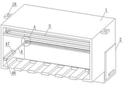
FIG. 1 is a schematic view of the overall structure of the present invention;
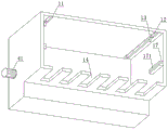
FIG. 2 is a bottom view of the cutting box structure of the present invention;
FIG. 3 is an enlarged view taken at A of FIG. 1 in accordance with the present invention;
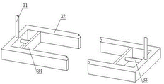
FIG. 4 is a schematic view of a clamping arrangement of the present invention;
fig. 5 is a schematic view of the bottom plate structure of the present invention.
In the figure: 1. cutting the box; 11. a top wall groove; 12. a first lead screw; 13. a thread block; 14. an inlet tank; 15. an opening; 16. a base plate; 161. vibrating the block; 17. a protection block; 171. a cutter groove; 18. mounting blocks; 2. a box door; 3. a clamping structure; 31. an electric push rod; 32. a square frame; 33. a cylinder member; 34. an auxiliary plate; 4. cutting the structure; 41. a drive motor; 42. a side groove; 43. a second lead screw; 44. a moving block; 45. a connecting rod; 46. installing a frame; 47. a cutting knife.
Detailed Description
The technical solutions in the embodiments of the present invention will be clearly and completely described below with reference to the drawings in the embodiments of the present invention, and it is obvious that the described embodiments are only a part of the embodiments of the present invention, and not all of the embodiments. All other embodiments, which can be derived by a person skilled in the art from the embodiments given herein without making any creative effort, shall fall within the protection scope of the present invention.
In order to solve the technical problems that rice is generally not clamped above the cutting mechanism in the use process, the rice can fall on the ground after being cut, the rice needs to be loaded manually, the operation is troublesome, the use is inconvenient, and the use effect is not ideal, as shown in fig. 1-5, the following preferable technical scheme is provided:
the utility model provides a rice is cutting mechanism for harvesting equipment, includes cutting case 1 and sets up at the inboard cutting structure 4 of cutting case 1, and the articulated chamber door 2 of installing on the lateral wall of cutting case 1, the inboard of cutting case 1 is provided with presss from both sides tight structure 3.
The clamping structure 3 comprises an electric push rod 31 arranged on the inner side of the cutting box 1 and a square frame 32 fixedly installed at the lower end of the electric push rod 31, wherein two groups of cylinder parts 33 are arranged on the inner wall of the square frame 32, and an auxiliary plate 34 is installed at one end of each of the two groups of cylinder parts 33.
The top wall groove 11 has been seted up on the top inner wall of cutting case 1, and top wall groove 11 is provided with two sets ofly, two sets of top wall groove 11 inboard all be provided with first lead screw 12, the outside of first lead screw 12 is cup jointed and is installed screw thread piece 13, and the external motor output of first lead screw 12, installation piece 18 is all installed at the both ends of cutting case 1.
An inlet groove 14 is uniformly formed in the front end of the cutting box 1, an opening 15 is formed in one side of the cutting box 1, a bottom plate 16 is arranged inside the cutting box 1, and a protection block 17 is arranged on the inner wall of the cutting box 1.
The bottom plate 16 is disposed in an inclined manner, and a vibration block 161 is disposed at the lower end of the bottom plate 16, and the vibration block 161 is externally connected with a vibration motor.
A cutter groove 171 is formed on one side of the protection block 17.
The cutting structure 4 comprises a driving motor 41 arranged on the outer wall of the cutting box 1 and a side groove 42 arranged on the inner wall of the cutting box 1, a second screw rod 43 is arranged on the inner side of the side groove 42, and the output end of the driving motor 41 is connected with one end of the second screw rod 43.
A moving block 44 is sleeved on the outer side of the second lead screw 43 through threads, a connecting rod 45 is installed on one side of the moving block 44, and an installation frame 46 is installed on the other end of the connecting rod 45.
Cutting blades 47 are mounted on two sides of the mounting frame 46, and the cutting blades 47 and the cutter grooves 171 are on the same horizontal line.
Specifically, in the process, an operator can install the cutting box 1 at the front end of the cutting machine through the installation block 18 and the bolt, when the cutting machine moves, the inlet slot 14 at the front end of the cutting box 1 can be in contact with rice, so that the rice is positioned at the inner side of the inlet slot 14, at the moment, the operator can use the switch to enable the electric push rod 31 to work, the electric push rod 31 can enable the square frame 32 to push the square frame 32 to move downwards, so that the upper part of the rice is positioned in the square frame 32, then the air cylinder 33 can be used for pushing the auxiliary plates 34 to move until the two groups of auxiliary plates 34 clamp the rice for facilitating subsequent cutting, after clamping, the operator can start the driving motor 41 to work to enable the second screw rod 43 to rotate, and can enable the moving block 44 to drive the connecting rod 45, the installation frame 46 and the mounting block 47 to move rightwards by matching with the use of the moving block 44, namely, the cutting knife can cut the rice, and when the cutting knife 47 moves to the rightmost side of the cutting box 1, at the moment, the cutting knife 47 is positioned in the knife groove 171, the cutting knife 47 is prevented from causing abrasion to the cutting box 1, after rice is cut, the motor is started to work, the first screw rod 12 is enabled to rotate, the threaded block 13 can be enabled to drive the clamping structure 3 to move until the square frame 32 is moved to the rear end inside the cutting box 1, the two groups of air cylinder components 33 are enabled to drive the two groups of auxiliary plates 34 to move towards two sides by utilizing the switch again, the rice can fall into the cutting box 1 at the moment, the rice can be collected without manual collection, the use is convenient, when the rice storage inside the cutting box 1 is full, the box door 2 is opened, the opening 15 is exposed, the rice can slide downwards along the inclined plane of the bottom plate 16, if the rice cannot slide downwards, the vibration motor is started to work, the vibration block 161 is enabled to work, and the bottom plate 16 can vibrate, is convenient for discharging the rice and has good use effect.
It is noted that, herein, relational terms such as first and second, and the like may be used solely to distinguish one entity or action from another entity or action without necessarily requiring or implying any actual such relationship or order between such entities or actions. Also, the terms "comprises," "comprising," or any other variation thereof, are intended to cover a non-exclusive inclusion, such that a process, method, article, or apparatus that comprises a list of elements does not include only those elements but may include other elements not expressly listed or inherent to such process, method, article, or apparatus.
Although embodiments of the present invention have been shown and described, it will be appreciated by those skilled in the art that changes, modifications, substitutions and alterations can be made in these embodiments without departing from the principles and spirit of the utility model, the scope of which is defined in the appended claims and their equivalents.
Claims (8)
1. The utility model provides a cutting mechanism for rice harvesting equipment, includes cutting case (1) and sets up at cutting structure (4) of cutting case (1) inboard, its characterized in that: the side wall of the cutting box (1) is hinged with a box door (2), and the inner side of the cutting box (1) is provided with a clamping structure (3);
the clamping structure (3) comprises an electric push rod (31) arranged on the inner side of the cutting box (1) and a square frame (32) fixedly installed at the lower end of the electric push rod (31), air cylinder pieces (33) are arranged on the inner wall of the square frame (32), two groups of air cylinder pieces (33) are arranged, and auxiliary plates (34) are installed at one ends of the two groups of air cylinder pieces (33).
2. The cutting mechanism for rice harvesting equipment of claim 1, wherein: the top wall groove (11) has been seted up on the top inner wall of cutting case (1), and top wall groove (11) are provided with two sets ofly, two sets of top wall groove (11) inboard all be provided with first lead screw (12), the outside of first lead screw (12) is cup jointed and is installed screw thread piece (13), and the external motor output of first lead screw (12), installation piece (18) are all installed at the both ends of cutting case (1).
3. The cutting mechanism for rice harvesting equipment of claim 2, wherein: the front end of the cutting box (1) is uniformly provided with an inlet groove (14), one side of the cutting box (1) is provided with an opening (15), a bottom plate (16) is arranged inside the cutting box (1), and the inner wall of the cutting box (1) is provided with a protection block (17).
4. The cutting mechanism for rice harvesting equipment of claim 3, wherein: the bottom plate (16) is obliquely arranged, a vibrating block (161) is arranged at the lower end of the bottom plate (16), and the vibrating block (161) is externally connected with a vibrating motor.
5. The cutting mechanism for rice harvesting equipment of claim 3, wherein: a cutter groove (171) is arranged on one side of the protection block (17).
6. The cutting mechanism for rice harvesting equipment of claim 3, wherein: the cutting structure (4) comprises a driving motor (41) arranged on the outer wall of the cutting box (1) and a side groove (42) arranged on the inner wall of the cutting box (1), a second screw rod (43) is arranged on the inner side of the side groove (42), and the output end of the driving motor (41) is connected with one end of the second screw rod (43).
7. The cutting mechanism for rice harvesting equipment of claim 6, wherein: the outer side of the second screw rod (43) is sleeved with a moving block (44) in a threaded mode, a connecting rod (45) is installed on one side of the moving block (44), and an installation frame (46) is installed at the other end of the connecting rod (45).
8. The cutting mechanism for rice harvesting equipment of claim 7, wherein: cutting knives (47) are installed on two sides of the installation frame (46), and the cutting knives (47) and the knife grooves (171) are located on the same horizontal line.
Priority Applications (1)
| Application Number | Priority Date | Filing Date | Title |
|---|---|---|---|
| CN202122998721.4U CN216218839U (en) | 2021-12-02 | 2021-12-02 | Cutting mechanism for rice harvesting equipment |
Applications Claiming Priority (1)
| Application Number | Priority Date | Filing Date | Title |
|---|---|---|---|
| CN202122998721.4U CN216218839U (en) | 2021-12-02 | 2021-12-02 | Cutting mechanism for rice harvesting equipment |
Publications (1)
| Publication Number | Publication Date |
|---|---|
| CN216218839U true CN216218839U (en) | 2022-04-08 |
Family
ID=80961300
Family Applications (1)
| Application Number | Title | Priority Date | Filing Date |
|---|---|---|---|
| CN202122998721.4U Active CN216218839U (en) | 2021-12-02 | 2021-12-02 | Cutting mechanism for rice harvesting equipment |
Country Status (1)
| Country | Link |
|---|---|
| CN (1) | CN216218839U (en) |
-
2021
- 2021-12-02 CN CN202122998721.4U patent/CN216218839U/en active Active
Similar Documents
| Publication | Publication Date | Title |
|---|---|---|
| CN211440751U (en) | Plastic coarse crusher | |
| CN215392968U (en) | Nut processing tool | |
| CN216218839U (en) | Cutting mechanism for rice harvesting equipment | |
| CN112691904A (en) | High efficiency agricultural product sieving mechanism | |
| CN218657026U (en) | Trimming device is used in production of car cantilever support assembly | |
| CN213703535U (en) | Raw materials cutting device is used in container bag production | |
| CN109434206A (en) | A kind of machining tool that cutting scrap is efficiently collected | |
| CN214159886U (en) | Waste paper collection device is used in carton processing | |
| CN212602211U (en) | Waste discharge device for die-cutting machine | |
| CN207983489U (en) | A kind of paperboard bead cutter | |
| CN113319942A (en) | Cutting machine for wood working convenient to collect saw-dust | |
| CN217564858U (en) | Automatic processingequipment of nut opening | |
| CN210209415U (en) | Workbench for steel processing | |
| CN218083171U (en) | Board cutting saw with dust removal function | |
| CN214871007U (en) | Slitter edge cutting device for printing packaging | |
| CN212707121U (en) | Three-side book cutter | |
| CN217663738U (en) | Double-shaft crusher | |
| CN217944025U (en) | A scrape limit equipment for production of melamine tableware | |
| CN220464124U (en) | Cutting machine with collection function | |
| CN208509653U (en) | A kind of stalk board cutting equipment | |
| CN212123516U (en) | Automatic clear useless function module of clear useless machine | |
| CN220029535U (en) | Copper strips filiform waste recovery unit | |
| CN218699112U (en) | Food processing device convenient to leftover bits are retrieved | |
| CN212945767U (en) | Synchronous trimming die for forming rear cover of notebook computer screen | |
| CN216858423U (en) | Electromechanical shell cutting equipment with function is collected to piece |
Legal Events
| Date | Code | Title | Description |
|---|---|---|---|
| GR01 | Patent grant | ||
| GR01 | Patent grant |