CN216215242U - High-efficiency energy-saving power transformation cabinet matched with 10KV of 110KV transformer substation - Google Patents
High-efficiency energy-saving power transformation cabinet matched with 10KV of 110KV transformer substation Download PDFInfo
- Publication number
- CN216215242U CN216215242U CN202121288054.4U CN202121288054U CN216215242U CN 216215242 U CN216215242 U CN 216215242U CN 202121288054 U CN202121288054 U CN 202121288054U CN 216215242 U CN216215242 U CN 216215242U
- Authority
- CN
- China
- Prior art keywords
- mounting
- shell
- transformer substation
- transformer
- fixed connection
- Prior art date
- Legal status (The legal status is an assumption and is not a legal conclusion. Google has not performed a legal analysis and makes no representation as to the accuracy of the status listed.)
- Active
Links
Images


Landscapes
- Casings For Electric Apparatus (AREA)
Abstract
The utility model discloses a high-efficiency energy-saving transformer cabinet matched with 10KV of a 110KV transformer substation, which comprises a shell, wherein a cabinet door is fixedly installed on one side of the shell, a plurality of through holes are formed in one side of the shell, a heat dissipation dustproof assembly is arranged in the shell and comprises a mounting frame, an ash blocking net, a compression ring, a first rotating shaft, fan blades, a mounting disc and a second rotating shaft, a damping and noise reduction assembly is arranged at the bottom end in the shell, and a top cover is fixedly connected to the top of the shell; according to the technical scheme provided by the utility model, the shock absorption is carried out on the electrical equipment in the power transformation cabinet by arranging the plurality of shock absorption and noise reduction assemblies, when the electrical equipment in the power transformation cabinet generates shock during operation, the shock is transmitted to the mounting block through the bottom plate, the mounting block is subjected to shock absorption through the spring in the mounting box, and the shock of the mounting box is reduced by sliding the sliding block on the side wall of the sliding way, so that the shock of the electrical equipment in the power transformation cabinet is reduced.
Description
Technical Field
The utility model relates to the technical field of power transformation cabinets, in particular to a high-efficiency and energy-saving power transformation cabinet matched with a 10KV transformer substation of a 110KV transformer substation.
Background
The transformer cabinet is a distribution device, is a box body of a place for transforming, concentrating and distributing the voltage and the current of electric energy in an electric power system, and is used for ensuring the quality of the electric energy and the safety of the device.
The prior art has the following defects or problems:
1. in the use process of the existing power transformation cabinet, electrical equipment in the power transformation cabinet generates large vibration and noise during operation, the vibration can cause that the wiring terminals of some electrical equipment are too loose and poor in contact, the problems of short circuit and the like can be caused seriously, and the noise can influence the daily work of people around;
2. the dust in the transformer cabinet can fly to outside the transformer cabinet through the through-hole when current transformer cabinet dispels the heat through the fan to pollute the surrounding environment, but if do not open the fan, can lead to high temperature in the transformer cabinet, lead to electrical equipment to damage.
SUMMERY OF THE UTILITY MODEL
The utility model aims to provide a high-efficiency and energy-saving transformer cabinet matched with a 110KV transformer substation and 10KV to solve the problems in the background technology, aiming at the defects in the prior art.
In order to achieve the purpose, the utility model provides the following technical scheme: the utility model provides a supporting energy-efficient transformer cabinet of 110KV transformer substation 10KV, includes the shell, shell one side fixed mounting has the cabinet door, a plurality of through-hole has been seted up to shell one side, the inside dustproof subassembly of heat dissipation that is provided with of shell, the dustproof subassembly of heat dissipation includes mounting bracket, shelves ash screen, clamping ring, first pivot, flabellum, mounting disc and second pivot, the inside bottom of shell is provided with vibration/noise reduction subassembly, shell top fixedly connected with top cap.
Optionally, the mounting bracket is fixedly connected inside the shell, the second rotating shaft is rotatably connected on the inner wall of the mounting bracket, the mounting disc is fixedly connected on the side wall of the second rotating shaft, a through hole is formed in the mounting disc, a motor is fixedly connected to one side of the mounting disc, the first rotating shaft is fixedly connected on the output end of the motor, and the fan blades are fixedly connected on the side wall of the first rotating shaft.
Optionally, a spring is fixedly connected between the compression ring and the mounting disc, and the ash blocking net is fixedly mounted between the compression ring and the mounting disc.
Optionally, the vibration/noise reduction assembly comprises an installation block, an installation box, a limiting part fixing part, a connecting rod, a sliding block and a sliding way, and the vibration/noise reduction assembly is provided with a plurality of parts.
Optionally, a bottom plate is installed inside the housing, and a gap between the bottom plate and the housing forms an installation cavity.
Optionally, the mounting block is fixedly connected to the inner wall of the mounting cavity, the mounting box is slidably connected to the side wall of the mounting block, the limiting part is fixedly connected to the side wall of the mounting block, the limiting part is located inside the mounting box, a spring is fixedly connected between one side of the limiting part and the inner wall of the mounting box, and the spring is located on the side wall of the mounting block.
Optionally, the fixing part is fixedly connected to the bottom of the mounting box, the connecting rod is movably connected to the inside of the fixing part, the sliding block is fixedly connected to one end of the connecting rod, the sliding way is fixedly connected to the inside of the mounting cavity, the sliding block is connected to the side wall of the sliding way in a sliding mode, the side wall of the sliding way is provided with a spring, and the side wall of the sliding way is provided with a limiting ring.
Compared with the prior art, the utility model provides a high-efficiency energy-saving power transformation cabinet matched with a 110KV transformer substation and 10KV, which has the following beneficial effects:
1. the shock absorption and noise reduction assembly is arranged to absorb shock of electrical equipment in the power transformation cabinet, when the electrical equipment in the power transformation cabinet generates shock during operation, the shock is transmitted to the mounting block through the bottom plate, the mounting block is damped through the spring in the mounting box, and the shock of the mounting box is reduced by sliding the sliding block on the side wall of the sliding way, so that the shock of the electrical equipment in the power transformation cabinet is reduced;
2. according to the utility model, the fan is arranged to radiate heat in the power transformation cabinet, dust in the power transformation cabinet can be blown out of the power transformation cabinet in the operation process of the fan, the dust blocking net is arranged to prevent the dust from flying out of the power transformation cabinet, and after the power transformation cabinet is used for a period of time, the pressing ring can be pulled up by rotating the mounting disc, so that the dust blocking net is taken out for cleaning, and the influence of excessive dust on the use of the power transformation cabinet is prevented.
Drawings
In order to more clearly illustrate the embodiments of the present invention or the technical solutions in the prior art, the drawings used in the description of the embodiments or the prior art will be briefly described below, it is obvious that the drawings in the following description are only some embodiments of the present invention, and for those skilled in the art, other drawings can be obtained according to the structures shown in the drawings without creative efforts.
FIG. 1 is a schematic view of the present invention;
FIG. 2 is a schematic structural view of the present invention;
FIG. 3 is an enlarged view taken at A of FIG. 2 according to the present invention;
FIG. 4 is an enlarged view of the utility model at B in FIG. 2.
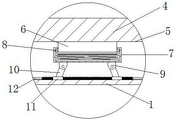
In the figure: 1. a housing; 2. a top cover; 3. a cabinet door; 4. a base plate; 5. a mounting cavity; 6. mounting blocks; 7. mounting a box; 8. a limiting member; 9. a fixing member; 10. a connecting rod; 11. a slider; 12. a slideway; 13. a mounting frame; 14. a dust blocking net; 15. pressing a ring; 16. a first rotating shaft; 17. a fan blade; 18. a through hole; 19. mounting a disc; 20. a second rotating shaft.
Detailed Description
The technical solutions in the embodiments of the present invention will be clearly and completely described below with reference to the drawings in the embodiments of the present invention, and it is obvious that the described embodiments are only a part of the embodiments of the present invention, and not all of the embodiments. All other embodiments, which can be derived by a person skilled in the art from the embodiments given herein without making any creative effort, shall fall within the protection scope of the present invention.
In the description of the present invention, it should be noted that the terms "vertical", "upper", "lower", "horizontal", and the like indicate orientations or positional relationships based on those shown in the drawings, and are only for convenience of describing the present invention and simplifying the description, but do not indicate or imply that the referred device or element must have a specific orientation, be constructed and operated in a specific orientation, and thus, should not be construed as limiting the present invention.
In the description of the present invention, it should be further noted that, unless otherwise specifically stated or limited, the terms "disposed," "mounted," "connected," and "connected" are to be construed broadly and may be, for example, fixedly connected, detachably connected, integrally connected, mechanically connected, electrically connected, directly connected, connected through an intermediate medium, or connected through the insides of two elements. The specific meanings of the above terms in the present invention can be understood by those skilled in the art according to specific situations.
Referring to fig. 1-4, in this embodiment: the utility model provides a supporting energy-efficient transformer cabinet of 110KV transformer substation 10KV, including shell 1, 1 one side fixed mounting of shell has cabinet door 3, a plurality of through-hole 18 has been seted up to 1 one side of shell, 1 inside dustproof subassembly that dispels the heat that is provided with of shell, the dustproof subassembly of heat dissipation includes mounting bracket 13, shelves ash screen 14, clamping ring 15, first pivot 16, flabellum 17, mounting disc 19 and second pivot 20, the inside bottom of shell 1 is provided with vibration/noise reduction subassembly, 1 top fixedly connected with top cap 2 of shell, prevent that the transformer cabinet rainwater from drenching inside electrical equipment when raining through setting up top cap 2, prevent that the dust of transformer cabinet in the heat dissipation process from being blown outside the transformer cabinet through setting up the dustproof subassembly of heat dissipation.
Further, the mounting frame 13 is fixedly connected inside the housing 1, the second rotating shaft 20 is rotatably connected to the inner wall of the mounting frame 13, the mounting disc 19 is fixedly connected to the side wall of the second rotating shaft 20, a through hole 18 is formed in the mounting disc 19, a motor is fixedly connected to one side of the mounting disc 19, the first rotating shaft 16 is fixedly connected to the output end of the motor, and the fan blade 17 is fixedly connected to the side wall of the first rotating shaft 16; the fan is arranged on one side of the through hole 18, so that the heat dissipation effect is better.
Further, a spring is fixedly connected between the pressing ring 15 and the mounting disc 19, and the ash blocking net 14 is fixedly mounted between the pressing ring 15 and the mounting disc 19; the dust that takes up when preventing the fan heat dissipation through setting up shelves ash net 14 flies outside the transformer cabinet, thereby can pull up shelves ash net 14 through rotating mounting disc 19 after using a period and clear up taking out shelves ash net 14, installs shelves ash net 14 through pulling up compression ring 15, conveniently clears up shelves ash net 14.
Furthermore, the vibration and noise reduction assembly comprises a mounting block 6, a mounting box 7, a limiting part 8 fixing part 9, a connecting rod 10, a sliding block 11 and a slide way 12, and the vibration and noise reduction assembly is provided with a plurality of vibration and noise reduction assemblies; the shock absorption is carried out on the electrical equipment in the power transformation cabinet by arranging the plurality of shock absorption and noise reduction assemblies.
Further, a bottom plate 4 is arranged in the shell 1, and a gap between the bottom plate 4 and the shell 1 forms a mounting cavity 5; the vibration/noise reduction assembly can be installed between the base plate 4 and the housing 1 by providing the installation cavity 5 between the base plate 4 and the housing 1.
Further, the mounting block 6 is fixedly connected to the inner wall of the mounting cavity 5, the mounting box 7 is slidably connected to the side wall of the mounting block 6, the limiting member 8 is fixedly connected to the side wall of the mounting block 6, the limiting member 8 is located inside the mounting box 7, a spring is fixedly connected between one side of the limiting member 8 and the inner wall of the mounting box 7, and the spring is located on the side wall of the mounting block 6; when the electrical equipment in the transformer cabinet generates vibration during operation, the vibration is transmitted to the mounting block 6 through the bottom plate 4, the mounting block 6 is damped through a spring in the mounting box 7, and the mounting block 6 is prevented from falling off from the inside of the mounting box 7 by arranging the limiting part 8.
Further, a fixing piece 9 is fixedly connected to the bottom of the mounting box 7, a connecting rod 10 is movably connected inside the fixing piece 9, a sliding block 11 is fixedly connected to one end of the connecting rod 10, a sliding way 12 is fixedly connected inside the mounting cavity 5, the sliding block 11 is slidably connected to the side wall of the sliding way 12, a spring is arranged on the side wall of the sliding way 12, and a limiting ring is arranged on the side wall of the sliding way 12; when the electrical equipment in the transformer cabinet generates vibration during operation, the mounting box 7 can move up and down due to the vibration in the process of damping the mounting block 6, and the sliding block 11 slides on the side wall of the slide rail 12 to extrude the spring on the side wall of the slide rail 12, so that the vibration of the mounting box 7 is reduced.
The working principle and the using process of the utility model are as follows: when the electric equipment in the transformer cabinet generates vibration during operation, the vibration is transmitted to the mounting block 6 through the bottom plate 4, the mounting block 6 is damped through the spring in the mounting box 7, the mounting block 6 is prevented from falling off from the inside of the mounting box 7 through the limiting part 8, the mounting box 7 can move up and down due to the vibration in the damping process of the mounting block 6, the spring on the side wall of the slideway 12 is slidingly extruded on the side wall of the slideway 12 through the sliding block 11, so that the vibration of the mounting box 7 is reduced, the vibration of the electric equipment in the transformer cabinet is reduced, high temperature is generated during the operation of the electric equipment in the transformer cabinet, heat dissipation is required, heat dissipation is performed in the transformer cabinet through the fan, dust in the transformer cabinet is blown out of the transformer cabinet during the operation of the fan, the environment is polluted, and the dust brought by the fan during the heat dissipation is prevented from flying out of the transformer cabinet through the arrangement of the gear mesh 14, after the dust blocking net 14 is used for a period of time, the installation disc 19 can be rotated to pull up the compression ring 15, so that the dust blocking net 14 can be taken out for cleaning, the compression ring 15 is pulled up to install the dust blocking net 14, and the dust blocking net 14 can be cleaned conveniently.
The above description is only a preferred embodiment of the present invention, and is not intended to limit the scope of the present invention, and all modifications and equivalents of the present invention, which are made by the contents of the present specification and the accompanying drawings, or directly/indirectly applied to other related technical fields, are included in the scope of the present invention.
Claims (7)
1. A110 KV transformer substation 10KV matching high-efficiency energy-saving transformer cabinet is characterized in that: including shell (1), shell (1) one side fixed mounting has cabinet door (3), a plurality of through-hole (18) have been seted up to shell (1) one side, the inside dustproof subassembly of heat dissipation that is provided with of shell (1), the dustproof subassembly of heat dissipation includes mounting bracket (13), ash blocking net (14), clamping ring (15), first pivot (16), flabellum (17), mounting disc (19) and second pivot (20), the inside bottom of shell (1) is provided with vibration/noise reduction subassembly, shell (1) top fixedly connected with top cap (2).
2. The efficient and energy-saving transformer cabinet matched with the 10KV transformer substation of the 110KV transformer substation of claim 1 is characterized in that: mounting bracket (13) fixed connection be in inside shell (1), second pivot (20) rotate to be connected mounting bracket (13) inner wall, mounting disc (19) fixed connection be in second pivot (20) lateral wall, through-hole (18) have been seted up in mounting disc (19), mounting disc (19) one side fixedly connected with motor, first pivot (16) fixed connection be in the motor output end, flabellum (17) fixed connection be in first pivot (16) lateral wall.
3. The efficient and energy-saving transformer cabinet matched with the 10KV transformer substation of the 110KV transformer substation of claim 1 is characterized in that: compression ring (15) with fixedly connected with spring between mounting disc (19), ash blocking net (14) fixed mounting in compression ring (15) with between mounting disc (19).
4. The efficient and energy-saving transformer cabinet matched with the 10KV transformer substation of the 110KV transformer substation of claim 1 is characterized in that: the vibration and noise reduction assembly comprises an installation block (6), an installation box (7), a limiting part (8), a fixing part (9), a connecting rod (10), a sliding block (11) and a slide way (12), and the vibration and noise reduction assembly is provided with a plurality of vibration and noise reduction assemblies.
5. The efficient and energy-saving transformer cabinet matched with the 10KV transformer substation of the 110KV transformer substation of claim 4 is characterized in that: the novel LED lamp is characterized in that a bottom plate (4) is arranged inside the shell (1), and a mounting cavity (5) is formed in a gap between the bottom plate (4) and the shell (1).
6. The efficient and energy-saving transformer cabinet matched with the 10KV transformer substation of the 110KV transformer substation of claim 5 is characterized in that: installation piece (6) fixed connection be in installation cavity (5) inner wall, mounting box (7) sliding connection be in installation piece (6) lateral wall, locating part (8) fixed connection be in installation piece (6) lateral wall, just locating part (8) are located inside mounting box (7), locating part (8) one side with fixedly connected with spring between mounting box (7) inner wall, the spring is located installation piece (6) lateral wall.
7. The efficient and energy-saving transformer cabinet matched with the 10KV transformer substation of the 110KV transformer substation of claim 5 is characterized in that: mounting (9) fixed connection be in mounting box (7) bottom, connecting rod (10) swing joint be in inside mounting (9), slider (11) fixed connection be in connecting rod (10) one end, slide (12) fixed connection be in inside installation cavity (5), slider (11) sliding connection be in slide (12) lateral wall, slide (12) lateral wall is provided with the spring, slide (12) lateral wall is provided with the spacing ring.
Priority Applications (1)
| Application Number | Priority Date | Filing Date | Title |
|---|---|---|---|
| CN202121288054.4U CN216215242U (en) | 2021-06-09 | 2021-06-09 | High-efficiency energy-saving power transformation cabinet matched with 10KV of 110KV transformer substation |
Applications Claiming Priority (1)
| Application Number | Priority Date | Filing Date | Title |
|---|---|---|---|
| CN202121288054.4U CN216215242U (en) | 2021-06-09 | 2021-06-09 | High-efficiency energy-saving power transformation cabinet matched with 10KV of 110KV transformer substation |
Publications (1)
| Publication Number | Publication Date |
|---|---|
| CN216215242U true CN216215242U (en) | 2022-04-05 |
Family
ID=80858810
Family Applications (1)
| Application Number | Title | Priority Date | Filing Date |
|---|---|---|---|
| CN202121288054.4U Active CN216215242U (en) | 2021-06-09 | 2021-06-09 | High-efficiency energy-saving power transformation cabinet matched with 10KV of 110KV transformer substation |
Country Status (1)
| Country | Link |
|---|---|
| CN (1) | CN216215242U (en) |
-
2021
- 2021-06-09 CN CN202121288054.4U patent/CN216215242U/en active Active
Similar Documents
| Publication | Publication Date | Title |
|---|---|---|
| CN110891386A (en) | Outdoor integrated cabinet for 5G base station | |
| CN216215242U (en) | High-efficiency energy-saving power transformation cabinet matched with 10KV of 110KV transformer substation | |
| CN210866888U (en) | New energy automobile high voltage distribution box | |
| CN212343155U (en) | Transformer substation outdoor installation box | |
| CN213426688U (en) | Control cabinet of 5G distributed base station | |
| CN211508213U (en) | Electrical safety switch cabinet | |
| CN220585824U (en) | Strong and weak electricity block terminal | |
| CN210577310U (en) | Safe energy-saving shockproof high-voltage complete switch equipment | |
| CN220674218U (en) | Self-heat-dissipation electric energy metering box | |
| CN215452197U (en) | Convenient mounting bracket for block terminal of dismantling | |
| CN215773980U (en) | Control cabinet cooling and adjusting device | |
| CN213662140U (en) | Electric cabinet convenient to installation | |
| CN215497676U (en) | 10KV switch cabinet with hoisting mechanism | |
| CN218216325U (en) | Box-type substation based on internet | |
| CN220710940U (en) | Outdoor comprehensive distribution box convenient for internal adjustment | |
| CN217563118U (en) | Distribution box with adjustable inner support | |
| CN210039858U (en) | Dry-type transformer with high-temperature power-off protection function | |
| CN220172689U (en) | Switch cabinet for electrical engineering | |
| CN213484296U (en) | Distribution box protection device | |
| CN216215250U (en) | High-low voltage cabinet with prevent empting structure | |
| CN210297006U (en) | Intelligent low-voltage comprehensive distribution box | |
| CN218919655U (en) | Intelligent power distribution device based on PLC control system | |
| CN211320710U (en) | Novel high-voltage switch cabinet | |
| CN211629690U (en) | Power equipment heat sink convenient to installation | |
| CN214590110U (en) | Dustproof high voltage distribution cabinet dispels heat |
Legal Events
| Date | Code | Title | Description |
|---|---|---|---|
| GR01 | Patent grant | ||
| GR01 | Patent grant |