CN216199266U - Variable frequency control cooling device - Google Patents
Variable frequency control cooling device Download PDFInfo
- Publication number
- CN216199266U CN216199266U CN202122391707.8U CN202122391707U CN216199266U CN 216199266 U CN216199266 U CN 216199266U CN 202122391707 U CN202122391707 U CN 202122391707U CN 216199266 U CN216199266 U CN 216199266U
- Authority
- CN
- China
- Prior art keywords
- water
- fixed
- motor
- variable frequency
- air duct
- Prior art date
- Legal status (The legal status is an assumption and is not a legal conclusion. Google has not performed a legal analysis and makes no representation as to the accuracy of the status listed.)
- Active
Links
Images


Landscapes
- Cooling Or The Like Of Electrical Apparatus (AREA)
Abstract
The utility model discloses a variable frequency control cooling device which comprises a box body, wherein two sides of the box body are respectively and fixedly connected with a shell and a connecting plate through fixing screws, the middle parts of the periphery of the inner wall of the box body are respectively provided with a sliding rail, the insides of four sliding rails are respectively and slidably connected with sliding strips, an air duct is fixedly arranged between the four sliding strips, one side of the air duct is fixedly provided with two fixing plates through the fixing screws, one side of the air duct, which is intersected with the two fixing plates, is fixedly provided with a motor, and the output end of the motor is fixedly provided with a rotary table. According to the cooling device capable of being regulated and controlled in a variable frequency mode, the four sliding strips and the four sliding rails can be connected in a sliding mode, so that the air duct and the motor can be conveniently disassembled and assembled, and the air duct and the motor can be more conveniently installed; the converter increases the output to the motor when the temperature is higher to make it increase the amount of wind, and the converter starts the water pump and cools down, makes the radiating effect better, and when the temperature reached the value of settlement, the converter closed the water pump and reduced the output to the motor, thereby prevents overcooling.
Description
Technical Field
The utility model relates to the technical field of cooling fans, in particular to a variable-frequency control cooling device.
Background
The cooling fan motor is a cooling system to remove heat and set them in the atmosphere, and the cooling fan is mainly used in industrial towers such as cooling towers or air coolers to cool the cooling towers and air coolers. The general cooling fan has the following problems:
1. the motor in the existing cooling fan generally adopts power frequency, so that the cooling fan has high energy consumption and no energy-saving effect, and the general fan only depends on the common blowing mode to dissipate heat, so that the cooling effect is poor
The inside of fan dryer produces the dust easily when using for a long time, and this can influence the life-span of motor, and general cooling blower's dryer is difficult to dismantle moreover, and it is very troublesome to maintain.
SUMMERY OF THE UTILITY MODEL
The utility model aims to provide a cooling device capable of being regulated and controlled in a variable frequency mode, and the cooling device is used for solving the problems that the control in the variable frequency mode cannot be realized, the heat dissipation effect is poor and an air cylinder is difficult to disassemble and assemble in the background technology.
In order to achieve the purpose, the utility model provides the following technical scheme: the utility model provides a cooling device of variable frequency accuse, includes the box, the both sides of box all are through set screw difference fixedly connected with shell and connecting plate, slide rail has all been seted up at box inner wall middle part all around, four the equal sliding connection in inside of slide rail has the draw runner, fixedly between four draw runners is equipped with the dryer, one side of dryer is equipped with two fixed plates through the set screw is fixed, two the fixed motor that is equipped with in one side that the fixed plate intersects, the fixed carousel that is equipped with of output of motor, the avris of carousel is fixed and is equipped with three flabellum, the fixed backup pad that is equipped with in bottom of box one side.
Preferably, the shell with the inside of connecting plate is equipped with a plurality of safety strip and dust screen respectively, four the screw with set screw matched with is all seted up to the one end of draw runner.
Preferably, a water circulation assembly is fixedly arranged at the top end of the supporting plate and comprises a water tank, an upper cover, a water pump, a water delivery pipe, a fixed frame and a plurality of condensation pipes, the water tank and the water pump are respectively and fixedly arranged at one side of the top end of the supporting plate and the middle of the top end of the supporting plate, and the water inlet end of the water pump is fixedly connected with the bottom of one side of the water tank through a connecting pipe.
Preferably, the fixed frame is fixed to be set up the inside one side of box, a plurality of condenser pipe fixed mounting is in the inside of fixed frame, and a plurality of the condenser pipe communicates each other.
Preferably, the top of the water tank is provided with a water filling port, and the upper cover is in threaded connection with the inner wall of the water filling port.
Preferably, one side of the top end of the box body is fixedly provided with a frequency converter and a temperature sensor respectively, the temperature sensor is electrically connected with the frequency converter, the bottom end of the water conveying pipe is fixedly connected with the water outlet end of the water pump, the other end of the water conveying pipe is fixedly connected with the water inlet end of one of the condensation pipes, and the water outlet end of the other condensation pipe is fixedly connected with the bottom of one side of the water tank through a connecting pipe.
Compared with the prior art, the utility model has the following beneficial effects:
according to the cooling device capable of being regulated and controlled in a variable frequency mode, the safety strips can prevent fan blades from hurting people when the fan blades rotate, the dust screen can reduce dust sucked into the air duct, the four sliding strips and the four sliding rails can be connected in a sliding mode, so that the air duct and the motor can be conveniently mounted and dismounted, and the air duct and the motor can be more conveniently mounted; the temperature-sensing ware can cooperate with the converter, and the temperature-sensing ware increases the output to the motor with temperature data transmission to converter when the temperature is higher to make it increase the amount of wind, and the converter starts the water pump and cools down, makes the radiating effect better, and when the temperature reached the value of settlement, the water pump was closed and the output to the motor was reduced to the converter, thereby prevented overcooling.
Drawings
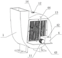
FIG. 1 is a schematic structural view of the present invention;
FIG. 2 is a schematic view of the water circulation assembly of the present invention;
FIG. 3 is a schematic view of the backside of the present invention;
FIG. 4 is a schematic structural diagram of an air duct according to the present invention;
fig. 5 is a schematic structural diagram of the slide rail according to the present invention.
In the figure: 1. a box body; 2. a housing; 3. an air duct; 4. a water circulation assembly; 41. a water tank; 42. an upper cover; 43. a water pump; 44. a water delivery pipe; 45. a fixing frame; 46. a condenser tube; 5. a fixing plate; 6. a slide bar; 7. a slide rail; 8. a motor; 9. a fan blade; 10. a turntable; 11. a support plate; 12. a temperature sensor; 13. a connecting plate; 14. and a frequency converter.
Detailed Description
The technical solutions in the embodiments of the present invention will be clearly and completely described below with reference to the drawings in the embodiments of the present invention, and it is obvious that the described embodiments are only a part of the embodiments of the present invention, and not all of the embodiments. All other embodiments, which can be derived by a person skilled in the art from the embodiments given herein without making any creative effort, shall fall within the protection scope of the present invention.
Referring to fig. 1-5, the utility model provides a variable frequency control cooling device, which comprises a box body 1, wherein two sides of the box body 1 are respectively and fixedly connected with a shell 2 and a connecting plate 13 through fixing screws, the middle parts of the periphery of the inner wall of the box body 1 are respectively provided with a slide rail 7, the insides of the four slide rails 7 are respectively and slidably connected with slide bars 6, an air duct 3 is fixedly arranged between the four slide bars 6, one side of the air duct 3 is fixedly provided with two fixing plates 5 through the fixing screws, one side of the crossed part of the two fixing plates 5 is fixedly provided with a motor 8, the output end of the motor 8 is fixedly provided with a rotary table 10, the side of the rotary table 10 is fixedly provided with three fan blades 9, and the bottom of one side of the box body 1 is fixedly provided with a supporting plate 11.
Preferably, a plurality of safety strips and a dust screen are respectively arranged inside the shell 2 and the connecting plate 13, screw holes matched with fixing screws are formed in one ends of the four sliding strips 6, the plurality of safety strips can prevent the fan blades 9 from hurting people when rotating, the dust screen can reduce dust sucked into the air duct 3, the four sliding strips 6 and the four sliding rails 7 can be in sliding connection, so that the air duct 3 and the motor 8 can be conveniently disassembled and assembled, the installation is more convenient, and the four sliding strips 6 can be fixedly connected with the shell 2 through the screw holes formed in one ends of the four sliding strips 6, and the air duct is more stable; the top end of the supporting plate 11 is fixedly provided with a water circulation assembly 4, the water circulation assembly 4 comprises a water tank 41, an upper cover 42, a water pump 43, a water delivery pipe 44, a fixing frame 45 and a plurality of condensation pipes 46, the water tank 41 and the water pump 43 are respectively and fixedly installed on one side of the top end of the supporting plate 11 and in the middle of the top end, the water inlet end of the water pump 43 is fixedly connected with the bottom of one side of the water tank 41 through a connecting pipe, and the water pump 43 can pump liquid in the water tank 41 into the plurality of condensation pipes 46, so that the temperature of blowing air is reduced; the fixing frame 45 is fixedly arranged at one side inside the box body 1, the plurality of condenser pipes 46 are fixedly arranged inside the fixing frame 45, the plurality of condenser pipes 46 are mutually communicated, and the plurality of mutually communicated condenser pipes 46 can take away heat through cooling liquid inside the water tank 41 and reduce the temperature of blown air; a water filling port is formed in the top of the water tank 41, and the upper cover 42 is connected with the upper cover 42 through threads on the inner wall of the water filling port to seal the water tank 41, so that the temperature inside the water tank is prevented from rising; one side on box 1 top is fixed respectively and is equipped with converter 14 and temperature-sensing ware 12, temperature- sensing ware 12 and 14 electric connection of converter, the bottom of raceway 44 and the play water end fixed connection of water pump 43, the other end of raceway 44 and the end fixed connection that intakes of one of them condenser pipe 46, the play water end of another condenser pipe 46 passes through the bottom fixed connection of connecting pipe and water tank 41 one side, temperature-sensing ware 12 can cooperate with converter 14, temperature-sensing ware 12 is with temperature data transmission to converter 14, converter 14 increases the output to motor 8 when the temperature is higher, thereby make it increase the amount of wind, and converter 14 starts water pump 43 and cools down, make the radiating effect better.
The working principle is as follows: the cooling device capable of being regulated and controlled by frequency conversion comprises a box body 1, an air duct 3, a plurality of safety strips, a dust screen, a motor 8, a rotary table 10, a temperature sensor 12, a sliding rail 7, a plurality of sliding strips 6, a plurality of sliding rails 7, a plurality of sliding rails 6, a plurality of sliding rails 3, a plurality of sliding rails 7, a plurality of sliding rails 3, a plurality of sliding rails 9, a plurality of sliding rails 10 and a plurality of sliding rails 10, wherein the sliding rails 7 are arranged in the box body 1 in a corresponding mode, the sliding rails are fixedly connected with the shell 2, the sliding rails are fixedly connected with the sliding rails, the sliding rails can prevent blades 9 from hurting people when rotating, the dust screen can reduce dust from being sucked into the air duct 3, the motor 8 is started through the frequency converter 12, the motor 10 is driven to rotate under the rotation of the motor 8, the rotary table 10, the rotary table 9 drives the three sliding blades 9 to rotate, so that the three sliding blades 9 generate wind power to dissipate heat and cool materials, and then set the temperature range of the temperature sensor 12, the temperature can be matched with the frequency converter 14, the temperature sensor 12, the frequency converter 14, thereby make its increase amount of wind to converter 14 starts water pump 43, and water pump 43 can squeeze into the inside coolant liquid of water tank 41 a plurality of condenser pipe 46's inside, and the condenser pipe 46 of a plurality of intercommunication each other takes away the heat on every side, and reduces the temperature of blowing out, makes the radiating effect better, and when the temperature reached the value of settlement, converter 14 closed water pump 43 and reduced the output to motor 8, thereby prevents overcooling.
In summary, the following steps: according to the cooling device capable of being regulated and controlled in a variable frequency mode, the safety strips can prevent the fan blades 9 from hurting people when rotating, the dust screen can reduce dust sucked into the air duct 3, the four sliding strips 6 and the four sliding rails 7 can be connected in a sliding mode, so that the air duct 3 and the motor 8 can be conveniently disassembled and assembled, the installation is more convenient, and the air duct can be fixedly connected with the shell 2 through the screw holes formed in one ends of the four sliding strips 6, so that the air duct is more stable; temperature-sensing ware 12 can cooperate with converter 14, and temperature-sensing ware 12 is with temperature data transmission to converter 14, and converter 14 increases the output to motor 8 when the temperature is higher to make it increase the amount of wind, and converter 14 starts water pump 43 and cools down, makes the radiating effect better, and when the temperature reached the value of settlement, converter 14 closed water pump 43 and reduced the output to motor 8, thereby prevents overcooling.
It is noted that, herein, relational terms such as first and second, and the like may be used solely to distinguish one entity or action from another entity or action without necessarily requiring or implying any actual such relationship or order between such entities or actions. Also, the terms "comprises," "comprising," or any other variation thereof, are intended to cover a non-exclusive inclusion, such that a process, method, article, or apparatus that comprises a list of elements does not include only those elements but may include other elements not expressly listed or inherent to such process, method, article, or apparatus.
Although embodiments of the present invention have been shown and described, it will be appreciated by those skilled in the art that changes, modifications, substitutions and alterations can be made in these embodiments without departing from the principles and spirit of the utility model, the scope of which is defined in the appended claims and their equivalents.
Claims (6)
1. The utility model provides a cooling device of variable frequency accuse, includes box (1), its characterized in that, the both sides of box (1) all are through set screw difference fixedly connected with shell (2) and connecting plate (13), slide rail (7) have all been seted up at box (1) inner wall middle part all around, four the equal sliding connection in inside of slide rail (7) has draw runner (6), fixedly between four draw runners (6) is equipped with dryer (3), one side of dryer (3) is equipped with two fixed plates (5) through set screw is fixed, two one side of fixed plate (5) cross department is fixed and is equipped with motor (8), the output end of motor (8) is fixed and is equipped with carousel (10), the avris of carousel (10) is fixed and is equipped with three flabellum (9), the bottom of box (1) one side is fixed and is equipped with backup pad (11).
2. A variable frequency controlled cooling apparatus as claimed in claim 1, wherein: the shell (2) and the inside of connecting plate (13) are equipped with a plurality of safety strip and dust screen respectively, four the screw with set screw matched with is all seted up to the one end of draw runner (6).
3. A variable frequency controlled cooling apparatus as claimed in claim 1, wherein: the water circulation assembly (4) is fixedly arranged at the top end of the supporting plate (11), the water circulation assembly (4) comprises a water tank (41), an upper cover (42), a water pump (43), a water pipe (44), a fixing frame (45) and a plurality of condensation pipes (46), the water tank (41) and the water pump (43) are respectively and fixedly installed on one side of the top end of the supporting plate (11) and the middle of the top end, and the water inlet end of the water pump (43) is fixedly connected with the bottom of one side of the water tank (41) through a connecting pipe.
4. A variable frequency controlled cooling apparatus as claimed in claim 3, wherein: fixed frame (45) are fixed to be set up the inside one side of box (1), a plurality of condenser pipe (46) fixed mounting is in the inside of fixed frame (45), and a plurality of condenser pipe (46) communicate each other.
5. A variable frequency controlled cooling apparatus as claimed in claim 3, wherein: the top of the water tank (41) is provided with a water filling port, and the upper cover (42) is in threaded connection with the inner wall of the water filling port.
6. A variable frequency controlled cooling apparatus as claimed in claim 3, wherein: a frequency converter (14) and a temperature sensor (12) are fixedly arranged on one side of the top end of the box body (1) respectively, the temperature sensor (12) is electrically connected with the frequency converter (14), the bottom end of the water conveying pipe (44) is fixedly connected with the water outlet end of the water pump (43), the other end of the water conveying pipe (44) is fixedly connected with the water inlet end of one of the condensation pipes (46), and the water outlet end of the other condensation pipe (46) is fixedly connected with the bottom of one side of the water tank (41) through a connecting pipe.
Priority Applications (1)
| Application Number | Priority Date | Filing Date | Title |
|---|---|---|---|
| CN202122391707.8U CN216199266U (en) | 2021-09-30 | 2021-09-30 | Variable frequency control cooling device |
Applications Claiming Priority (1)
| Application Number | Priority Date | Filing Date | Title |
|---|---|---|---|
| CN202122391707.8U CN216199266U (en) | 2021-09-30 | 2021-09-30 | Variable frequency control cooling device |
Publications (1)
| Publication Number | Publication Date |
|---|---|
| CN216199266U true CN216199266U (en) | 2022-04-05 |
Family
ID=80859742
Family Applications (1)
| Application Number | Title | Priority Date | Filing Date |
|---|---|---|---|
| CN202122391707.8U Active CN216199266U (en) | 2021-09-30 | 2021-09-30 | Variable frequency control cooling device |
Country Status (1)
| Country | Link |
|---|---|
| CN (1) | CN216199266U (en) |
-
2021
- 2021-09-30 CN CN202122391707.8U patent/CN216199266U/en active Active
Similar Documents
| Publication | Publication Date | Title |
|---|---|---|
| CN209963861U (en) | Efficient cooling device for internal heat exchange of large motor | |
| CN216199266U (en) | Variable frequency control cooling device | |
| CN218183841U (en) | Heat radiation structure of UPS power | |
| CN214279480U (en) | Liquid crystal splicing screen with heat dissipation function | |
| CN211352723U (en) | Industrial automation control cabinet | |
| CN103838337A (en) | Data center server cooling equipment cabinet | |
| CN210226043U (en) | Automatic change heat abstractor for equipment | |
| CN113410773A (en) | Information engineering low-voltage cabinet device | |
| CN208723822U (en) | A kind of frequency converter cabinet of modified form | |
| CN211601628U (en) | Energy-saving cooling tower | |
| CN220020201U (en) | Industrial explosion-proof flat plate with protection structure for heat dissipation | |
| CN220769791U (en) | Cooling structure of fan frequency converter | |
| CN102752993A (en) | Forced-cooling circulation structure for server without fan | |
| CN218102151U (en) | High-efficient heat dissipation type switch board | |
| CN217882354U (en) | Low-voltage fixed switch cabinet with heat dissipation function | |
| CN216673676U (en) | Cooling device with quick locking structure for data center | |
| CN220436893U (en) | Energy-saving and environment-friendly multifunctional refrigeration equipment | |
| CN217783771U (en) | High-efficiency energy-saving two-stage screw type air compressor | |
| CN219415290U (en) | Variable-frequency triple household type ground source heat pump | |
| CN219961211U (en) | Variable-frequency air source heat pump refrigerating, heating and hot water triple-generation unit | |
| CN219388158U (en) | Cooling mechanism of water ring vacuum pump | |
| CN220541255U (en) | High-temperature air cooler | |
| CN220307685U (en) | Server evaporative cooling equipment suitable for under high temperature environment | |
| CN216218405U (en) | Heat dissipation device of electric automation equipment | |
| CN217155013U (en) | Utilize multistage power generation system of cement kiln waste heat |
Legal Events
| Date | Code | Title | Description |
|---|---|---|---|
| GR01 | Patent grant | ||
| GR01 | Patent grant |