Energy-concerving and environment-protective architectural decoration rail guard
Technical Field
The utility model relates to the technical field of protective guards, in particular to an energy-saving and environment-friendly architectural decoration protective guard.
Background
Guard rail: the industrial protective fence or crash-proof guardrail is mainly used for protecting and protecting equipment and facilities in factories, workshops and warehouses.
With the development of science and technology and the improvement of the living standard of people, the requirement of people on the convenience of development of things is higher, the prior protective guard does not have a convenient connecting and disassembling device, so that people cannot conveniently adjust the stable communication of the protective guard when in use, and the energy-saving and environment-friendly architectural decoration protective guard is provided to solve the problem.
SUMMERY OF THE UTILITY MODEL
Technical problem to be solved
Aiming at the defects of the prior art, the utility model provides an energy-saving and environment-friendly architectural decoration protective guard which has the advantages that the protective guard is convenient to connect and detach, can conveniently adjust the stable communication of the protective guard and the like, and the problem that the stable communication of the protective guard cannot be conveniently adjusted is solved.
(II) technical scheme
In order to realize the purposes that the protective guard is provided with a convenient connecting and disassembling device and can conveniently adjust the stable communication of the protective guard, the utility model provides the following technical scheme: an energy-saving and environment-friendly architectural decoration protective guard comprises a stable bottom plate, a transition plate and a stable vertical plate, wherein a communication mechanism is fixedly connected to the outside of the stable vertical plate, and a transmission mechanism for controlling stability is arranged inside the stable vertical plate;
the communication mechanism comprises a first supporting plate, an insertion rod, a second supporting plate and a connecting insert ring, wherein the first supporting plate is positioned on one side of a stable vertical plate and fixedly connected with the stable vertical plate, the insertion rod is fixedly connected to the side edge of the first supporting plate, the second supporting plate is fixedly connected to the side edge of the stable vertical plate, and the connecting insert ring is fixedly connected to the side edge of the second supporting plate;
transmission device is including supporting stabilizer plate, control dwang, stabilizing the rotating ring and can dismantling the shock pad, the inside fixedly connected with quantity of stabilizing the riser is two supports stabilizer plate, two it is connected with the control dwang to support to rotate between the stabilizer plate, the outside rotation of control dwang is connected with stabilizes the rotating ring, the outside of stabilizing the rotating ring has been laid and has been dismantled the shock pad.
Furthermore, the transition plate is located the top and the PMKD fixed connection of PMKD, the top fixed connection who crosses the transition plate is two to stabilize the riser.
Furthermore, the transition plate is flat, the top of the transition plate is provided with two slots fixedly connected with the stabilizing vertical plates, the stabilizing vertical plates are connected with the transition plate in a welding mode, and the transition plate is fixedly connected with the stabilizing bottom plate through screws.
Further, stabilize the riser and constitute by quantity for two bracing pieces and middle transmission board, and the connected mode of bracing piece and transmission board is the welding.
Furthermore, the insertion rod is long-strip-shaped, the front surface of the insertion rod is provided with an insertion rod hole, and the insertion rod is connected with the first supporting plate in a welding mode.
Furthermore, connect and insert the ring for square ring form, and connect the front of inserting the ring and set up the stable jack that distributes evenly and insert the pole intercommunication.
Furthermore, the supporting and stabilizing plate is in a vertical plate shape, the opposite sides of the supporting and stabilizing plates on the two sides are provided with stabilizing rotating grooves which are rotatably connected with the supporting and stabilizing plate, and the connecting mode of the supporting and stabilizing plate and the stabilizing vertical plate is welding.
Further, stabilize the swivel becket and be cylindric, and stabilize the top of swivel becket and offer the stable jack of being connected with the control dwang is stable.
(III) advantageous effects
Compared with the prior art, the utility model provides an energy-saving and environment-friendly architectural decoration protective guard, which has the following beneficial effects:
this energy-concerving and environment-protective architectural decoration rail guard, through setting up the cab apron of crossing of stabilizing bottom plate top fixed connection, through the stability of crossing the cab apron, the support of the stable riser in control top that can rapid stabilization, insert the pole through the setting and peg graft to another a set of guardrail and connect the inside of inserting the ring, thereby the connection of regulation guardrail that can be convenient, insert the bolt through connecting the front of inserting the ring again, thereby can the stable connection of convenient control guardrail, thereby can be convenient the stable transmission of control guardrail, again through setting up support stabilizer plate and control dwang, the rotation of the control stabilizer ring that can be quick, bond outside can dismantle the shock pad through stabilizing the swivel ring, conflict through dismantling the shock pad, can effectively cushion, user's use has been made things convenient for.
Drawings
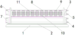
FIG. 1 is a schematic structural view of the present invention;
fig. 2 is a side view of the structure of the present invention.
In the figure: 1 stabilizing bottom plate, 2 cross cab apron, 3 stabilize the riser, 4 first backup pad, 5 insert the pole, 6 second backup pads, 7 connect and insert the ring, 8 support stabilizer plate, 9 control dwang, 10 stabilize the swivel becket, 11 can dismantle the shock pad.
Detailed Description
The technical solutions in the embodiments of the present invention will be clearly and completely described below with reference to the drawings in the embodiments of the present invention, and it is obvious that the described embodiments are only a part of the embodiments of the present invention, and not all of the embodiments. All other embodiments, which can be derived by a person skilled in the art from the embodiments given herein without making any creative effort, shall fall within the protection scope of the present invention.
Referring to fig. 1-2, an energy-saving and environment-friendly architectural decoration protective guard comprises a stable bottom plate 1, a transition plate 2 and a stable vertical plate 3, wherein the stable vertical plate 3 is fixedly connected with a communicating mechanism at the outside, the stable vertical plate 3 is internally provided with a transmission mechanism for controlling stability, the communicating mechanism comprises a first supporting plate 4, an inserting rod 5, a second supporting plate 6 and a connecting insert ring 7, the first supporting plate 4 is positioned at one side of the stable vertical plate 3 and is fixedly connected with the stable vertical plate 3, the side of the first supporting plate 4 is fixedly connected with the inserting rod 5, the side of the stable vertical plate 3 is fixedly connected with the second supporting plate 6, the side of the second supporting plate 6 is fixedly connected with the connecting insert ring 7, the transition plate 2 fixedly connected with the top of the stable bottom plate 1 is arranged, the top of the stable vertical plate 3 can be rapidly and stably controlled by the stability of the transition plate 2, the inserting rod 5 is arranged to be inserted into another group of guardrail connecting insert rings 7, thereby the connection of the guardrail can be conveniently adjusted, and the stable connection of the guardrail can be conveniently controlled by inserting the bolt in the front of the connecting insert ring 7, thereby the stable transmission of the guardrail can be conveniently controlled, the transmission mechanism comprises a supporting stabilizing plate 8, a control rotating rod 9, a stabilizing rotating ring 10 and a detachable shock pad 11, the internal part of the stabilizing vertical plate 3 is fixedly connected with two supporting stabilizing plates 8, the control rotating rod 9 is rotatably connected between the two supporting stabilizing plates 8, the external part of the control rotating rod 9 is rotatably connected with the stabilizing rotating ring 10, the detachable shock pad 11 is laid outside the stabilizing rotating ring 10, the rotation of the stabilizing rotating ring 10 can be rapidly controlled by arranging the supporting stabilizing plates 8 and the control rotating rod 9, the external detachable shock pad 11 is bonded by the stabilizing rotating ring 10, and is abutted by the detachable shock pad 11, the shock can be effectively absorbed.
In this embodiment, the transition plate 2 is located the top of the stable bottom plate 1 and is fixedly connected with the stable bottom plate 1, and the top fixedly connected with number of the transition plate 2 is two stable vertical plates 3.
In this embodiment, cross cab apron 2 and be flat, and cross the top of cab apron 2 and offer quantity for two and stable riser 3 fixed connection's slot, stable riser 3 is the welding with the connected mode of crossing cab apron 2, crosses cab apron 2 and stable bottom plate 1 and passes through screw fixed connection, and stable riser 3 comprises the bracing piece that quantity is two and middle transmission board, and the connected mode of bracing piece and transmission board is the welding to can convenient control top stable riser 3's stable centre gripping.
In this embodiment, insert pole 5 is rectangular form, and the inserted bar hole has been seted up in the front of inserting pole 5, and the connected mode of inserting pole 5 and first backup pad 4 is the welding, connects insert ring 7 and is square ring-shaped, and connects insert ring 7's front and set up the stable jack that evenly distributes and insert pole 5 intercommunication, pegs graft to the inside of connecting insert ring 7 through inserting pole 5 to can the connection of two guardrails of convenient control.
In this embodiment, support stabilizer plate 8 and be the riser form, and the opposite side that both sides supported stabilizer plate 8 all sets up and supports stabilizer plate 8 and rotate the stable groove of changeing of being connected, supports stabilizer plate 8 and the connected mode of stabilizing riser 3 and is the welding, and it is cylindric to stabilize swivel 10, and the top of stabilizing swivel 10 sets up the stable jack of being connected with control dwang 9 to can adjust the rotation of internal control dwang 9 and stable swivel 10.
The beneficial effects of the above embodiment are as follows:
this energy-concerving and environment-protective architectural decoration rail guard, through setting up cab apron 2 of crossing of 1 top fixed connection of stable bottom plate, through crossing the stability of cab apron 2, the support of riser 3 is stabilized at the control top that can rapid stabilization, insert the inside of inserting ring 7 through setting up to insert 5 grafting to another a set of guardrail connection, thereby the connection of regulation guardrail that can be convenient, insert the bolt through connecting the front of inserting ring 7 again, thereby can be convenient the stable connection of control guardrail, thereby can be convenient the stable transmission of control guardrail, again through setting up support stabilizer plate 8 and control dwang 9, the rotation of rotor ring 10 is stabilized in the control that can be quick, through stabilizing rotor ring 10 bonding outside can dismantle shock pad 11, through the conflict that can dismantle shock pad 11, can effectively the shock attenuation, user's use has been made things convenient for.
The electrical components shown herein are electrically connected to a main controller and a power supply, the main controller can be a conventional known device controlled by a computer, and the conventional power connection technology disclosed in the prior art is not described in detail herein.
It is noted that, herein, relational terms such as first and second, and the like may be used solely to distinguish one entity or action from another entity or action without necessarily requiring or implying any actual such relationship or order between such entities or actions. Also, the terms "comprises," "comprising," or any other variation thereof, are intended to cover a non-exclusive inclusion, such that a process, method, article, or apparatus that comprises a list of elements does not include only those elements but may include other elements not expressly listed or inherent to such process, method, article, or apparatus. Without further limitation, an element defined by the phrase "comprising an … …" does not exclude the presence of other identical elements in a process, method, article, or apparatus that comprises the element.
Although embodiments of the present invention have been shown and described, it will be appreciated by those skilled in the art that changes, modifications, substitutions and alterations can be made in these embodiments without departing from the principles and spirit of the utility model, the scope of which is defined in the appended claims and their equivalents.