CN216190455U - Heavy hoisting equipment with trolley for monorail crane - Google Patents
Heavy hoisting equipment with trolley for monorail crane Download PDFInfo
- Publication number
- CN216190455U CN216190455U CN202122563657.7U CN202122563657U CN216190455U CN 216190455 U CN216190455 U CN 216190455U CN 202122563657 U CN202122563657 U CN 202122563657U CN 216190455 U CN216190455 U CN 216190455U
- Authority
- CN
- China
- Prior art keywords
- trolley
- pulley
- lifting
- monorail
- cross beam
- Prior art date
- Legal status (The legal status is an assumption and is not a legal conclusion. Google has not performed a legal analysis and makes no representation as to the accuracy of the status listed.)
- Active
Links
Images
Landscapes
- Carriers, Traveling Bodies, And Overhead Traveling Cranes (AREA)
Abstract
The utility model discloses heavy hoisting equipment with trolleys for a monorail crane, which comprises a monorail, wherein a hanging beam group A and a hanging beam group B are connected below the monorail in a sliding manner, the hanging beam group A and the hanging beam group B are connected through a connecting rod and a connector, the hanging beam group A and the hanging beam group B respectively comprise a main cross beam and a bearing beam, the main cross beam and the bearing beam are connected through the connecting rod and the connector, the upper end surfaces of the two ends of the main cross beam and the bearing beam are respectively connected with a trolley connecting beam, the two ends of the trolley connecting beam are connected with trolleys, and the top end of each trolley is connected to the outer surface of the monorail in a sliding manner. The utility model improves the lifting efficiency and distance, effectively reduces the transportation cost and is safe and reliable.
Description
Technical Field
The utility model relates to the technical field of underground coal mine hoisting devices, in particular to heavy hoisting equipment with a trolley for a monorail crane.
Background
At present, an explosion-proof diesel engine monorail crane is increasingly popularized and applied as efficient underground auxiliary transportation equipment; the most important link of the transport equipment by using the monorail hoist is hoisting.
However, the existing hoisting equipment usually matched with the monorail crane generally comprises a pneumatic hoisting beam, a hydraulic oil cylinder hoisting beam and a manual hoisting beam. The pneumatic lifting beam has the defects of fixed air source, low lifting tonnage and the like; the common hydraulic oil cylinder lifting beam usually occupies a higher space of a roadway, so that the lifting distance is greatly limited; manual lifting of the lifting beam is laborious and time-consuming, and has many potential safety hazards.
SUMMERY OF THE UTILITY MODEL
The utility model aims to provide heavy lifting equipment with a trolley for a monorail crane, which aims to overcome the defects of fixed air source, low lifting tonnage and the like of a pneumatic lifting beam in the background technology; the common hydraulic oil cylinder lifting beam usually occupies a higher space of a roadway, so that the lifting distance is greatly limited; the utility model provides a heavy hydraulic lifting beam of a monorail crane, which has the problems of labor and time waste, potential safety hazards and the like.
In order to achieve the purpose, the utility model provides the following technical scheme: a heavy hoisting device with trolleys for a monorail crane comprises a monorail, wherein a hanging beam group A and a hanging beam group B are connected to the lower portion of the monorail in a sliding mode, the hanging beam group A and the hanging beam group B are connected through a connecting rod and a connector, the hanging beam group A and the hanging beam group B both comprise a main cross beam and a bearing beam, the main cross beam and the bearing beam are connected through the connecting rod and the connector, trolley connecting beams are connected to the upper end faces of the two ends of the main cross beam and the two ends of the bearing beam, the two ends of each trolley connecting beam are connected with trolleys, and the top ends of the trolleys are connected to the outer surface of the monorail in a sliding mode;
a lifting beam is connected between the adjacent main cross beam and the bearing beam of the lifting beam group A and between the adjacent main cross beam and the bearing beam of the lifting beam group B through chains, a cross-shaped cross beam with a pulley trolley is movably connected to the middle position of the lifting beam, two ends of the cross-shaped cross beam with the pulley trolley are movably connected with lifting cylinders, and a pulley with a chain wheel is connected between every two bottom ends in the direction parallel to the monorail through chains;
one end of the main cross beam of the hanging beam group A is fixedly provided with a manual valve A, one end of the bearing beam of the hanging beam group B is fixedly provided with a manual valve B, the manual valve A and the manual valve B are connected with a hoisting chain, the hoisting chain passes through a corresponding pulley with a chain wheel, and the other end of the hoisting chain is fixed on the main cross beam of the hanging beam group A.
Preferably, connectors are fixedly arranged at two ends of the main cross beam and two ends of the bearing beam, and the top ends of the connectors are connected with the end portions of the connecting rods through short shafts.
Preferably, the lower part of the middle part of the trolley connecting beam is connected with the two ends of the main cross beam or the two ends of the bearing beam through shaft pins.
Preferably, the cross beam of the pulley vehicle is arranged in the lifting beam, and the pulley with the chain wheel, the lifting cylinder and the cross beam of the pulley vehicle form a pulley combination together.
Preferably, the both ends of the coaster of taking the sprocket are equipped with the sprocket, the jack-up chain passes the sprocket surface, manual valve A and manual valve B's inside is equipped with hydraulic block, hydraulic block is connected with the one end of jack-up chain, jack-up chain's the lowest end swing joint has the couple.
Preferably, the manual valve a and the manual valve B are connected with the corresponding lifting cylinders through hydraulic pipelines.
Compared with the prior art, the utility model has the beneficial effects that:
the lifting device comprises a lifting cylinder, a manual valve A, a manual valve B, a hydraulic hoist, a pulley, a chain wheel, a lifting beam, a chain wheel, a chain wheel and a lifting beam.
Drawings
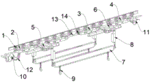
Fig. 1 is a schematic structural view of the whole of the present invention.
In the figure: 1. a trolley; 2. a trolley connecting beam; 3. a main cross beam; 4. a spandrel girder; 5. a cross beam of the scooter; 6. lifting the lifting beam; 7. a pulley with a sprocket; 8. a lift cylinder; 9. a hoisting chain; 10. a manual valve A; 11. a manual valve B; 12. a hydraulic line; 13. a connecting rod; 14. a connector is provided.
Detailed Description
The technical solutions in the embodiments of the present invention will be clearly and completely described below with reference to the drawings in the embodiments of the present invention, and it is obvious that the described embodiments are only a part of the embodiments of the present invention, and not all of the embodiments.
Referring to fig. 1, an embodiment of the present invention: a heavy hoisting device with trolleys for a monorail crane comprises a monorail, wherein a hanging beam group A and a hanging beam group B are connected to the lower portion of the monorail in a sliding mode, the hanging beam group A and the hanging beam group B are connected through a connecting rod 13 and a connector 14, the hanging beam group A and the hanging beam group B respectively comprise a main cross beam 3 and a bearing beam 4, the main cross beam 3 and the bearing beam 4 are connected through the connecting rod 13 and the connector 14, the upper end faces of two ends of the main cross beam 3 and the bearing beam 4 are connected with trolley connecting beams 2, two ends of each trolley connecting beam 2 are connected with trolleys 1, and the top end of each trolley 1 is connected to the outer surface of the monorail in a sliding mode;
a lifting beam 6 is respectively connected between the adjacent main cross beam 3 and the bearing beam 4 of the lifting beam group A and between the adjacent main cross beam 3 and the bearing beam 4 of the lifting beam group B through chains, a cross-shaped cross beam 5 with a pulley trolley is movably connected at the middle position of the lifting beam 6, two ends of the cross-shaped cross beam 5 with the pulley trolley are movably connected with lifting cylinders 8, and a pulley 7 with a chain wheel is connected between every two bottom ends of the cross-shaped cross beam 5 with the pulley trolley in the direction parallel to the monorail through chains;
one end of the main beam 3 of the hanging beam group A is fixedly provided with a manual valve A10, one end of the bearing beam 4 of the hanging beam group B is fixedly provided with a manual valve B11, the manual valve A10 and the manual valve B11 are connected with a hoisting chain 9, the hoisting chain 9 passes through the corresponding pulley 7 with a chain wheel, and the other end of the hoisting chain is fixed on the main beam 3 of the hanging beam group A.
Furthermore, connectors 14 are fixedly arranged at two ends of the main cross beam 3 and two ends of the bearing beam 4, and the top ends of the connectors 14 are connected with the end portions of the connecting rods 13 through short shafts.
Furthermore, the lower part of the middle part of the trolley connecting beam 2 is connected with the two ends of the main beam 3 or the two ends of the bearing beam 4 through shaft pins.
Further, a cross beam of the cross beam 5 with the pulley car is arranged in the lifting beam 6, and the pulley 7 with the chain wheel, the lifting cylinder 8 and the cross beam 5 with the pulley car jointly form a pulley combination.
Furthermore, chain wheels are arranged at two ends of the pulley 7 with the chain wheels, the hoisting chain 9 penetrates through the outer surfaces of the chain wheels, hydraulic hoists are arranged inside the manual control valve A10 and the manual control valve B11 and are connected with one end of the hoisting chain 9, and the lowest end of the hoisting chain 9 is movably connected with a hook.
Further, the manual valve a10 and the manual valve B11 are connected to the corresponding lift cylinder 8 through the hydraulic line 12.
When in use, the hoisting beam 6 is connected with the main beam 3 and the bearing beam 4 by using a rotary hoisting ring, pulleys in the main beam 3 are used for longitudinal compensation in a curve, the beam of the cross beam 5 with the pulley vehicle is arranged in the hoisting beam 6, the pulleys can also ensure the longitudinal compensation in the curve, the lifting cylinder 8 is fixed on the cross beam 5 with the pulley vehicle by using a rotary joint, the pulley 7 with a chain wheel is also connected with the lifting cylinder 8, the lifting cylinder 8 is controlled by using a manual valve A10 and a manual valve B11, the lifting chain 9 on the manual valve A10 and the manual valve B11 is pulled, so that the pulley 7 with the chain wheel and a load can be lifted or lowered, the lifting or the lowering can be carried out independently or together, the lifting movement of the transport tool is controlled by a hydraulic system, and hydraulic liquid is provided for the transport tool by a driving unit; the utility model can lift 48 tons, the rated load is 1.8m/min higher than the lifting speed, and the utility model has the advantages of strong lifting capability, convenient operation, short transportation time, safety, reliability and the like.
It will be evident to those skilled in the art that the utility model is not limited to the details of the foregoing illustrative embodiments, and that the present invention may be embodied in other specific forms without departing from the spirit or essential attributes thereof. The present embodiments are therefore to be considered in all respects as illustrative and not restrictive, the scope of the utility model being indicated by the appended claims rather than by the foregoing description, and all changes which come within the meaning and range of equivalency of the claims are therefore intended to be embraced therein. Any reference sign in a claim should not be construed as limiting the claim concerned.
Claims (6)
1. The utility model provides a monorail crane is with heavy lifting means of band pulley, includes the monorail, its characterized in that: a hanging beam group A and a hanging beam group B are connected below the monorail in a sliding mode, the hanging beam group A and the hanging beam group B are connected through a connecting rod (13) and a connector (14), the hanging beam group A and the hanging beam group B both comprise a main cross beam (3) and a bearing beam (4), the main cross beam (3) and the bearing beam (4) are connected through the connecting rod (13) and the connector (14), the upper end faces of the two ends of the main cross beam (3) and the bearing beam (4) are both connected with trolley connecting beams (2), the two ends of the trolley connecting beams (2) are connected with hoisting trolleys (1), and the top end of each hoisting trolley (1) is connected to the outer surface of the monorail in a sliding mode;
a lifting beam (6) is connected between the adjacent main cross beam (3) and the bearing beam (4) of the lifting beam group A and between the adjacent main cross beam (3) and the bearing beam (4) of the lifting beam group B through chains, a cross beam (5) with a pulley trolley is movably connected at the middle position of the lifting beam (6), lifting cylinders (8) are movably connected at two ends of the cross beam (5) with the pulley trolley, and a pulley (7) with a chain wheel is connected between every two bottom ends of the cross beam (5) with the pulley trolley in the direction parallel to the monorail through chains;
one end fixed mounting of the main beam (3) of the hanging beam group A is provided with a manual valve A (10), one end fixed mounting of the bearing beam (4) of the hanging beam group B is provided with a manual valve B (11), the manual valve A (10) and the manual valve B (11) are connected with a hoisting chain (9), and the hoisting chain (9) penetrates through a corresponding pulley (7) with a chain wheel and the other end of the corresponding pulley (7) is fixed on the main beam (3) of the hanging beam group A.
2. The heavy lifting equipment with the trolley for the monorail crane, as claimed in claim 1, is characterized in that: both ends of main beam (3) and spandrel girder (4) all are fixed and are equipped with connector (14), connector (14) top is passed through the minor axis with the tip of connecting rod (13) and is connected.
3. The heavy hoisting equipment with the trolley for the monorail crane as claimed in claim 1, wherein: the lower part of the middle part of the trolley connecting beam (2) is connected with the two ends of the main cross beam (3) or the two ends of the bearing beam (4) through shaft pins.
4. The heavy hoisting equipment with the trolley for the monorail crane as claimed in claim 1, wherein: the cross beam of the cross beam (5) with the pulley car is arranged in a lifting beam (6), and the pulley (7) with the chain wheel, the lifting cylinder (8) and the cross beam (5) with the pulley car jointly form a pulley combination.
5. The heavy hoisting equipment with the trolley for the monorail crane as claimed in claim 1, wherein: the both ends of taking coaster (7) of sprocket are equipped with the sprocket, sprocket surface is passed in jack-up chain (9), the inside of manual valve A (10) and manual valve B (11) is equipped with hydraulic block, hydraulic block is connected with the one end of jack-up chain (9), the least significant end swing joint of jack-up chain (9) has the couple.
6. The heavy hoisting equipment with the trolley for the monorail crane as claimed in claim 1, wherein: and the manual valve A (10) and the manual valve B (11) are connected with the corresponding lifting cylinder (8) through a hydraulic pipeline (12).
Priority Applications (1)
| Application Number | Priority Date | Filing Date | Title |
|---|---|---|---|
| CN202122563657.7U CN216190455U (en) | 2021-10-25 | 2021-10-25 | Heavy hoisting equipment with trolley for monorail crane |
Applications Claiming Priority (1)
| Application Number | Priority Date | Filing Date | Title |
|---|---|---|---|
| CN202122563657.7U CN216190455U (en) | 2021-10-25 | 2021-10-25 | Heavy hoisting equipment with trolley for monorail crane |
Publications (1)
| Publication Number | Publication Date |
|---|---|
| CN216190455U true CN216190455U (en) | 2022-04-05 |
Family
ID=80888429
Family Applications (1)
| Application Number | Title | Priority Date | Filing Date |
|---|---|---|---|
| CN202122563657.7U Active CN216190455U (en) | 2021-10-25 | 2021-10-25 | Heavy hoisting equipment with trolley for monorail crane |
Country Status (1)
| Country | Link |
|---|---|
| CN (1) | CN216190455U (en) |
Cited By (1)
| Publication number | Priority date | Publication date | Assignee | Title |
|---|---|---|---|---|
| CN113928975A (en) * | 2021-10-25 | 2022-01-14 | 沙尔夫矿山机械(徐州)有限公司 | Heavy hoisting equipment with trolley for monorail crane |
-
2021
- 2021-10-25 CN CN202122563657.7U patent/CN216190455U/en active Active
Cited By (1)
| Publication number | Priority date | Publication date | Assignee | Title |
|---|---|---|---|---|
| CN113928975A (en) * | 2021-10-25 | 2022-01-14 | 沙尔夫矿山机械(徐州)有限公司 | Heavy hoisting equipment with trolley for monorail crane |
Similar Documents
| Publication | Publication Date | Title |
|---|---|---|
| CN201546631U (en) | Telescopic mast drill derrick | |
| CN102556854B (en) | Mine hydraulic hoisting traveling crane | |
| CN216190455U (en) | Heavy hoisting equipment with trolley for monorail crane | |
| CN108190738B (en) | Hoisting and transporting device for mining monorail crane | |
| CN113998592A (en) | Pneumatic underground hoisting device for monorail crane | |
| CN204098952U (en) | A kind of coal mine roadway centre mounted type container handling equipment | |
| CN103318774B (en) | Self-assembly/self-disassembly hoisting device, crane and self-assembly/self-disassembly method of hoister | |
| CN202346632U (en) | Mine hydraulic type lifting crane | |
| CN207060197U (en) | A kind of new all-hydraulic automatic dismantling counterweight, track beam multifunctional drill chassis | |
| CN205170186U (en) | Finished product anchor clamps of laying bricks | |
| CN113928975A (en) | Heavy hoisting equipment with trolley for monorail crane | |
| CN101898724A (en) | Double-jaw grab bucket fetching device | |
| CN216190463U (en) | Novel 20T monorail crane heavy lifting beam | |
| CN115676648A (en) | Multifunctional underground maintenance vehicle | |
| CN216190454U (en) | Pneumatic underground hoisting device for monorail crane | |
| CN205114887U (en) | Hand propelled removes portal frame | |
| CN205113097U (en) | Crawler -type mountain transport vehicle carriage vertical lifting device | |
| CN209410079U (en) | A kind of full-automatic monorail crane rail switch system | |
| CN209940322U (en) | Crawler-type stack type support transfer cart | |
| CN111776926A (en) | Mine cradle replacing device and replacing method thereof | |
| CN105398952A (en) | Finished brick clamp | |
| CN202417589U (en) | Electric single-beam suspension transportation device | |
| CN218231561U (en) | Adjustable lifting beam of pneumatic monorail crane | |
| CN205932997U (en) | Mine overhead line electric locomotive rail transport hoisting accessory | |
| CN208089246U (en) | Chain-type cat road promotes dynamical system |
Legal Events
| Date | Code | Title | Description |
|---|---|---|---|
| GR01 | Patent grant | ||
| GR01 | Patent grant |