CN216181186U - Punching machine convenient to align location fast - Google Patents
Punching machine convenient to align location fast Download PDFInfo
- Publication number
- CN216181186U CN216181186U CN202122292840.8U CN202122292840U CN216181186U CN 216181186 U CN216181186 U CN 216181186U CN 202122292840 U CN202122292840 U CN 202122292840U CN 216181186 U CN216181186 U CN 216181186U
- Authority
- CN
- China
- Prior art keywords
- threaded rod
- motor
- base
- bevel gear
- positioning
- Prior art date
- Legal status (The legal status is an assumption and is not a legal conclusion. Google has not performed a legal analysis and makes no representation as to the accuracy of the status listed.)
- Active
Links
Images


Abstract
The utility model discloses a punching machine convenient for quick alignment and positioning, which comprises: a motor is arranged in the base, the motor is of a double-shaft structure, and the right end of the motor is connected with a first threaded rod; the fixed plate is arranged above the base, and a second threaded rod is rotatably connected inside the fixed plate; and the rotating shaft is arranged in the base, and the tail end of the rotating shaft is connected with the left side of the motor. This piercing press convenient to quick alignment location, because the motor is the biax type structure, the motor during operation can drive first threaded rod and axis of rotation simultaneously and rotate, accessible connecting block drives the backup pad when first threaded rod rotates and removes, the first bevel gear of accessible drives second bevel gear and rotates when the axis of rotation rotates, accessible connecting axle drives the second threaded rod and rotates when second bevel gear rotates, make the guide block drive the gag lever post and move down along its surface, thereby the person of facilitating the use fixes a position fast between with work piece and the drift.
Description
Technical Field
The utility model relates to the technical field of punching machines, in particular to a punching machine convenient for quick alignment and positioning.
Background
The punching machine is a movable part numerical control device for sheet processing, punching, die pressing, embossing and the like, which forcibly presses metal to enter a die, is suitable for punching processing of leather, cowsheepskin, artificial leather, plastics, PU, EVA, PVC, various cloth, paper, leather ornaments, vamps, decorative sheets, curtains, automobile leather chairs and the like, is widely applied to industries such as automobile accessories, luggage handbags, stationery, shoes, breathable materials, advertisement paper products and the like, along with the development of the society, the types of the punching machine emerging on the market are more and more, but the existing punching machine also has certain defects, such as:
when the existing device is used, an inconvenient user aligns workpieces and punches quickly, so that the work efficiency of the user is influenced, the existing device is inconvenient to adjust according to the size of the workpieces when in use, the inconvenient user fixes the workpieces of different sizes and clamps the workpieces, and then the user is limited when in use.
Those skilled in the art have therefore endeavored to develop a punch that facilitates quick alignment positioning.
Disclosure of Invention
In view of the above-mentioned defects of the prior art, the present invention is to solve the technical problems that the prior device is inconvenient to align quickly, adjust according to the size of the workpiece and adjust the position of the punch.
To achieve the above object, the present invention provides a punching machine facilitating quick alignment and positioning, comprising:
preferably, a motor is arranged in the base, the motor is of a double-shaft structure, the right end of the motor is connected with a first threaded rod, and meanwhile, the outer surface of the first threaded rod is in threaded connection with a connecting block;
the fixed plate is arranged above the base, a second threaded rod is rotatably connected inside the fixed plate, a guide block is connected to the outer surface of the second threaded rod in a threaded manner, and the tail end of the guide block is in sliding connection with the inside of the fixed plate;
the rotating shaft is arranged in the base, the tail end of the rotating shaft is connected with the left side of the motor, a first bevel gear is arranged on the outer surface of the rotating shaft, and a second bevel gear is meshed and connected with the outer surface of the first bevel gear;
the connecting shaft is arranged inside the base, the upper end of the connecting shaft is connected with the lower end of the second threaded rod, and a second bevel gear is arranged on the outer surface of the second threaded rod.
Preferably, the lower end of the connecting block is connected with the base in a sliding mode, a supporting plate is arranged at the upper end of the connecting block, and the supporting plate is of an existing telescopic structure.
Preferably, the upper end of the supporting plate is provided with a fixing frame, first springs are installed inside the fixing frame at equal intervals, and the tail ends of the first springs are connected with clamping plates.
Preferably, both sides run through to the external world from the mount inside around the splint, and both sides lower extreme is provided with the bracing piece around the splint to the bracing piece sets up the surface at the mount.
Preferably, the guide block right side is provided with the gag lever post, and the gag lever post is concertina type structure to gag lever post end connection has the installation cover.
Preferably, the mounting sleeve forms a telescopic structure through the limiting rod and the guide block, and a second spring is mounted inside the mounting sleeve.
Preferably, the end of the second spring is connected with a punch, and the punch and the mounting sleeve form an elastic structure through the second spring.
The utility model has the beneficial effects that:
1. when the punching head is used, the motor is of a double-shaft structure, the motor can simultaneously drive the first threaded rod and the rotating shaft to rotate when working, the supporting plate can be driven to move by the connecting block when the first threaded rod rotates, the second bevel gear can be driven to rotate by the first bevel gear when the rotating shaft rotates, and the second threaded rod can be driven to rotate by the connecting shaft when the second bevel gear rotates, so that the limiting rod is driven by the guide block to move downwards along the outer surface of the guide block, a user can conveniently and quickly position a workpiece and a punching head, and the use requirements of the user are met;
2. when the clamping device is used, the supporting plate is of an existing telescopic structure, a user can adjust the length of the supporting plate according to the requirement of the user, the height of the clamping plate can be adjusted according to the width of a workpiece, the lower surface of the clamping plate is made of sponge materials, the phenomenon of scraping the outer surface of the workpiece is avoided, the clamping device is convenient for the user to adjust according to the size of the workpiece, and the clamping device is convenient for the user to use;
3. when the device is used, a user can adjust the distance between the guide block and the limiting rod according to the requirement of the user, so that the user can conveniently punch holes at different positions of a workpiece, and when the device is not used, the user can integrally store the punch head into the mounting sleeve, so that the service life of the punch head can be prolonged, the punch head can be prevented from being exposed outside to cause damage to the user, and the practicability of the device is improved.
Drawings
FIG. 1 is a schematic overall front cross-sectional structural view of an embodiment of the present invention;
FIG. 2 is a side view of the clamping plate and the support rod according to the embodiment of the present invention;
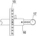
FIG. 3 is a schematic top view of the installation of a stop bar and a guide block according to an embodiment of the present invention;
FIG. 4 is a schematic view of a second spring and bit mounting internal structure according to an embodiment of the present invention;
fig. 5 is a schematic top view of the connection block and the first threaded rod according to the embodiment of the utility model.
Name of part
1. A base; 2. a motor; 3. connecting blocks; 4. a support plate; 5. a fixing plate; 6. a second threaded rod; 7. a rotating shaft; 8. a first bevel gear; 9. a second bevel gear; 10. a connecting shaft; 11. a fixed mount; 12. a first spring; 13. a splint; 14. a support bar; 15. a guide block; 16. a limiting rod; 17. installing a sleeve; 18. a second spring; 19. a punch; 20. a first threaded rod.
Detailed Description
The present invention will be further described with reference to the accompanying drawings and examples, wherein the terms "upper", "lower", "left", "right", "inner", "outer", and the like, as used herein, refer to an orientation or positional relationship indicated in the drawings, which is for convenience and simplicity of description, and does not indicate or imply that the referenced devices or components must be in a particular orientation, constructed and operated in a particular manner, and thus should not be construed as limiting the present invention. The terms "first," "second," "third," and the like are used for descriptive purposes only and are not to be construed as indicating or implying relative importance.
A motor 2 is arranged in the base 1, the motor 2 is of a double-shaft structure, the right end of the motor 2 is connected with a first threaded rod 20, and meanwhile the outer surface of the first threaded rod 20 is in threaded connection with a connecting block 3;
the fixed plate 5 is arranged above the base 1, the inner part of the fixed plate 5 is rotatably connected with the second threaded rod 6, the outer surface of the second threaded rod 6 is in threaded connection with the guide block 15, and meanwhile, the tail end of the guide block 15 is in sliding connection with the inner part of the fixed plate 5;
the rotating shaft 7 is arranged in the base 1, the tail end of the rotating shaft 7 is connected with the left side of the motor 2, a first bevel gear 8 is arranged on the outer surface of the rotating shaft 7, and a second bevel gear 9 is meshed and connected with the outer surface of the first bevel gear 8;
the connecting shaft 10 is arranged inside the base 1, the upper end of the connecting shaft 10 is connected with the lower end of the second threaded rod 6, and the outer surface of the second threaded rod 6 is provided with a second bevel gear 9;
threaded connection has a self-locking function, can improve the stability of being connected between first threaded rod 20 and connecting block 3 and second threaded rod 6 and the guide block 15, the guide rail has been preset to base 1 and fixed plate 5 inside, play direction limiting displacement to the removal of connecting block 3 and guide block 15 for it remains throughout to remove in this plane, and secondly 2 upsides of motor are provided with the heating panel, and its row of heat energy accessible that its during operation produced is external.
The lower end of the connecting block 3 is connected with the base 1 in a sliding manner, the upper end of the connecting block 3 is provided with a supporting plate 4, and the supporting plate 4 is arranged to be of an existing telescopic structure;
the design of the supporting plate 4 can play a role of fixing and supporting a workpiece to be processed, and the supporting plate 4 with a telescopic structure is convenient for a user to fix and clamp workpieces with different sizes.
A fixing frame 11 is arranged at the upper end of the supporting plate 4, first springs 12 are arranged in the fixing frame 11 at equal intervals, and the tail ends of the first springs 12 are connected with clamping plates 13;
the clamping plate 13 can form an elastic structure with the fixing frame 11 through the elasticity of the first spring 12, and the lower end of the clamping plate 13 is made of sponge materials, so that the workpiece is prevented from being damaged when being fixedly clamped.
The front side and the rear side of the clamping plate 13 penetrate through the fixed frame 11 to the outside, the lower ends of the front side and the rear side of the clamping plate 13 are provided with supporting rods 14, and the supporting rods 14 are arranged on the outer surface of the fixed frame 11;
the supporting rod 14 is of an existing electric push rod type structure, so that a user can adjust the distance between the clamping plate 13 and the fixing frame 11 according to the thickness of a workpiece, and the user can adjust the workpiece according to the size of the workpiece.
A limiting rod 16 is arranged on the right side of the guide block 15, the limiting rod 16 is of a telescopic structure, and the tail end of the limiting rod 16 is connected with an installation sleeve 17;
for sliding connection between guide block 15 and the gag lever post 16, convenience of customers adjusts the position of installation cover 17 through gag lever post 16, and fixes through the bolt between guide block 15 and the gag lever post 16 to ensure its stability of connecting.
The mounting sleeve 17 and the guide block 15 form a telescopic structure through a limiting rod 16, and a second spring 18 is mounted inside the mounting sleeve 17;
the mounting sleeve 17 can adjust the distance between the mounting sleeve and the guide block 15 through the limiting rod 16, so that a user can adjust the mounting position of the punch 19 according to the requirement of the user, and the user can punch holes in different positions of a workpiece conveniently.
The tail end of the second spring 18 is connected with a punch 19, and the punch 19 and the mounting sleeve 17 form an elastic structure through the second spring 18;
the punch 19 is fixed with the mounting sleeve 17 through a bolt, and when the punch is not used, a user can unscrew the bolt on the outer surface of the mounting sleeve 17, so that the punch 19 extends and retracts from the mounting sleeve 17 through the elasticity of the second spring 18, and the whole punch is contained in the mounting sleeve 17.
The working principle is as follows:
firstly, the length of the supporting plate 4 is adjusted according to the size of a workpiece, the supporting plate 4 is placed at the upper end of the supporting plate 4 when the adjustment is completed, then a user can electrify the supporting rod 14, so that the supporting rod 14 drives the clamping plate 13 to move downwards until the lower end of the clamping plate 13 is attached to the workpiece, the clamping plate 13 plays a role in fixing and clamping the workpiece, and the clamping plate 13 can stretch and retract with the fixing frame 11 through the elasticity of the first spring 12 while moving downwards, so that the movement of the clamping plate 13 is buffered;
next, the user can adjust the distance between the mounting sleeve 17 and the guide block 15 through the limiting rod 16, and then push the limiting rod 16, so that the limiting rod 16 moves along the outer surface of the guide block 15, the user can conveniently move the punch 19 to a proper position, and when the adjustment is completed, the user can fix the punch through a bolt, so that the connection stability of the punch is guaranteed;
when the adjustment is completed, a user can electrify the motor 2 to enable the motor 2 to drive the first threaded rod 20 to rotate, when the first threaded rod 20 rotates, the connecting block 3 can drive the supporting plate 4 to move leftwards along the upper end of the base 1 along the threads on the outer surface of the connecting block 3, when the motor 2 works, the rotating shaft 7 can drive the first bevel gear 8 to rotate, when the first bevel gear 8 rotates, the second bevel gear 9 can drive the connecting shaft 10 to rotate, when the connecting shaft 10 rotates, the second threaded rod 6 can be driven to rotate inside the fixing plate 5, when the second threaded rod 6 rotates, the guide block 15 can be driven to move downwards along the threads on the outer surface of the guide block, when the guide block 15 moves, the limiting rod 16 can be used for driving the mounting sleeve 17 to move downwards, when the mounting sleeve 17 moves downwards, the punch 19 can be driven to move downwards, so that a workpiece corresponds to the workpiece rapidly, and the workpiece is punched, when not using, the user can unscrew the bolt of installation cover 17 surface for drift 19 stretches out and draws back through the elasticity of second spring 18 and installation cover 17, thereby accomodates it wholly inside installation cover 17, avoids it to expose to the external world and causes the injury to the staff, has increased holistic practicality.
The foregoing detailed description of the preferred embodiments of the utility model has been presented. It should be understood that numerous modifications and variations could be devised by those skilled in the art in light of the present teachings without departing from the inventive concepts. Therefore, the technical solutions available to those skilled in the art through logic analysis, reasoning and limited experiments based on the prior art according to the concept of the present invention should be within the scope of protection defined by the claims.
Claims (7)
1. A punch machine for facilitating quick alignment positioning, comprising: base (1), characterized by: a motor (2) is arranged in the base (1), the motor (2) is of a double-shaft structure, the right end of the motor (2) is connected with a first threaded rod (20), and meanwhile, the outer surface of the first threaded rod (20) is in threaded connection with a connecting block (3);
the fixing plate (5) is arranged above the base (1), a second threaded rod (6) is rotatably connected inside the fixing plate (5), a guide block (15) is connected to the outer surface of the second threaded rod (6) in a threaded manner, and the tail end of the guide block (15) is in sliding connection with the inside of the fixing plate (5);
the rotating shaft (7) is arranged in the base (1), the tail end of the rotating shaft (7) is connected with the left side of the motor (2), a first bevel gear (8) is arranged on the outer surface of the rotating shaft (7), and a second bevel gear (9) is meshed and connected with the outer surface of the first bevel gear (8);
the connecting shaft (10) is arranged inside the base (1), the upper end of the connecting shaft (10) is connected with the lower end of the second threaded rod (6), and a second bevel gear (9) is arranged on the outer surface of the second threaded rod (6).
2. The punch machine for facilitating quick alignment and positioning of parts according to claim 1, wherein: connecting block (3) lower extreme and base (1) are sliding connection, and connecting block (3) upper end is provided with backup pad (4) to backup pad (4) set up to current concertina type structure.
3. The punch machine for facilitating quick alignment and positioning of parts according to claim 2, wherein: the supporting plate is characterized in that a fixing frame (11) is arranged at the upper end of the supporting plate (4), first springs (12) are installed inside the fixing frame (11) at equal intervals, and clamping plates (13) are connected to the tail ends of the first springs (12).
4. The punch machine for facilitating quick alignment and positioning of parts according to claim 3, wherein: both sides run through to the external world from mount (11) is inside around splint (13), and splint (13) front and back both sides lower extreme is provided with bracing piece (14) to bracing piece (14) set up the surface at mount (11).
5. The punch machine for facilitating quick alignment and positioning of parts according to claim 1, wherein: the right side of the guide block (15) is provided with a limiting rod (16), the limiting rod (16) is of a telescopic structure, and the tail end of the limiting rod (16) is connected with an installation sleeve (17).
6. The punch machine for facilitating quick alignment and positioning of parts according to claim 5, wherein: the mounting sleeve (17) and the guide block (15) form a telescopic structure through a limiting rod (16), and a second spring (18) is mounted inside the mounting sleeve (17).
7. The punch machine for facilitating quick alignment and positioning of parts according to claim 6, wherein: the tail end of the second spring (18) is connected with a punch (19), and the punch (19) and the mounting sleeve (17) form an elastic structure through the second spring (18).
Priority Applications (1)
| Application Number | Priority Date | Filing Date | Title |
|---|---|---|---|
| CN202122292840.8U CN216181186U (en) | 2021-09-18 | 2021-09-18 | Punching machine convenient to align location fast |
Applications Claiming Priority (1)
| Application Number | Priority Date | Filing Date | Title |
|---|---|---|---|
| CN202122292840.8U CN216181186U (en) | 2021-09-18 | 2021-09-18 | Punching machine convenient to align location fast |
Publications (1)
| Publication Number | Publication Date |
|---|---|
| CN216181186U true CN216181186U (en) | 2022-04-05 |
Family
ID=80921554
Family Applications (1)
| Application Number | Title | Priority Date | Filing Date |
|---|---|---|---|
| CN202122292840.8U Active CN216181186U (en) | 2021-09-18 | 2021-09-18 | Punching machine convenient to align location fast |
Country Status (1)
| Country | Link |
|---|---|
| CN (1) | CN216181186U (en) |
-
2021
- 2021-09-18 CN CN202122292840.8U patent/CN216181186U/en active Active
Similar Documents
| Publication | Publication Date | Title |
|---|---|---|
| CN207359685U (en) | A kind of automobile handware stamping equipment of automatic positioning | |
| CN216181186U (en) | Punching machine convenient to align location fast | |
| CN213827529U (en) | Laser marking machine with regulatory function | |
| CN216730734U (en) | Tool for numerical control machining | |
| CN209175862U (en) | A kind of die-cutting component for multistation die-cutting machine | |
| CN215315087U (en) | Motor rotor punching sheet processing assembly | |
| CN217116532U (en) | Polymer battery top FPC flexible circuit board device of buckling | |
| CN111793964A (en) | Tailoring has automatic positioning function's cutter | |
| CN220128858U (en) | Tail shearing device for telescopic hose | |
| CN220560708U (en) | Laser cutting unloader | |
| CN220347037U (en) | Sheet metal riveting raw material positioning auxiliary table | |
| CN219253820U (en) | Blanking die carrier based on die | |
| CN218947827U (en) | Efficient and smooth cutting decorative film production equipment | |
| CN220347364U (en) | Cutting device for processing UV printer | |
| CN217573055U (en) | PVC panel processingequipment | |
| CN210498633U (en) | Thin-wall steel structure section bar cutting machine | |
| CN220717393U (en) | U-shaped bolt forming device | |
| CN214359288U (en) | Automatic folding device that rolls of air pocket | |
| CN214138063U (en) | Embossing roller interval adjustable coining mill | |
| CN211640207U (en) | Chip punching device for manufacturing electronic products | |
| CN219214572U (en) | Positioning mechanism for wood art engraving | |
| CN216606777U (en) | Convenient bending mechanism | |
| CN213971555U (en) | Financial document puncher that facilitates use | |
| CN216857919U (en) | Copper bar slitting device with guiding function | |
| CN219280327U (en) | Cutting equipment with supplementary blade that changes |
Legal Events
| Date | Code | Title | Description |
|---|---|---|---|
| GR01 | Patent grant | ||
| GR01 | Patent grant |