CN216179206U - Trimming equipment for rubber rail lower base plate - Google Patents
Trimming equipment for rubber rail lower base plate Download PDFInfo
- Publication number
- CN216179206U CN216179206U CN202122517999.5U CN202122517999U CN216179206U CN 216179206 U CN216179206 U CN 216179206U CN 202122517999 U CN202122517999 U CN 202122517999U CN 216179206 U CN216179206 U CN 216179206U
- Authority
- CN
- China
- Prior art keywords
- trimming
- moving
- deburring
- sliding
- motor
- Prior art date
- Legal status (The legal status is an assumption and is not a legal conclusion. Google has not performed a legal analysis and makes no representation as to the accuracy of the status listed.)
- Active
Links
Images


Abstract
The utility model discloses trimming equipment for a lower base plate of a rubber rail, which belongs to the technical field of rubber processing and comprises a working frame, a trimming rotating mechanism, a trimming fixing mechanism, a trimming moving mechanism, a trimming mechanism and a dust cleaning mechanism, wherein the trimming rotating mechanism is rotationally connected to the working frame, the trimming fixing mechanism is positioned at the top of the working frame, the trimming moving mechanism is rotationally connected to the trimming fixing mechanism, the trimming mechanism is positioned on the trimming moving mechanism, and the dust cleaning mechanism is positioned on the trimming fixing mechanism. According to the utility model, the movable lead screw rotates to drive the position of the movable block to move on the movable slide rail, and the movable block moves to drive the position of the trimming grinding wheel to move, so that trimming operation is carried out on different positions on the base plate.
Description
Technical Field
The utility model relates to the technical field of rubber processing, in particular to trimming equipment for a rubber rail lower base plate.
Background
In the production process of the elastic base plate below the rubber base plate, the corners of the elastic base plate need to be trimmed according to the use requirement; however, the conventional apparatus has problems that firstly, the position of trimming cannot be adjusted according to the size of the pad plate, and secondly, the position of the pad plate cannot be rotated and only a single position of the pad plate can be trimmed.
SUMMERY OF THE UTILITY MODEL
The embodiment of the utility model provides trimming equipment for a rubber rail lower base plate, which aims to solve the problems in the prior art.
The embodiment of the utility model adopts the following technical scheme: the utility model provides a deburring equipment of rubber rail lower bolster, includes work frame, deburring rotary mechanism, deburring fixed establishment, deburring moving mechanism, deburring mechanism and dust clearance mechanism, deburring rotary mechanism rotates to be connected on the work frame, deburring fixed establishment is located the top of work frame, deburring moving mechanism rotates to be connected on deburring fixed establishment, deburring mechanism is located deburring moving mechanism, dust clearance mechanism is located deburring fixed establishment.
Furthermore, the trimming and rotating mechanism comprises a rotating motor and a rotating disk, a rotating groove is formed in the middle of the working frame, the rotating disk is rotatably connected in the rotating groove, the rotating motor is located at the bottom of the working frame, and a main shaft of the rotating motor is fixedly connected with the bottom of the rotating disk.
Further, deburring fixed establishment includes mount, fixed electric jar and fixed disk, the mount is located the top of mount, fixed electric jar is located the top of mount, the fixed disk is connected with the flexible end rotation of fixed electric jar.
Further, the trimming moving mechanism comprises a moving block, a moving lead screw, a moving motor and a moving slide rail, the moving slide rail is horizontally arranged at the top of the working frame, the moving lead screw is rotatably connected to the fixed frame, the moving block is in threaded connection with the moving lead screw, the bottom of the moving block is in sliding fit with the moving slide rail, the moving motor is located on the side wall of the fixed frame, and the moving motor is in transmission connection with the moving lead screw.
Furthermore, the trimming moving mechanism further comprises a sliding motor, a sliding plate and a sliding gear, wherein the bottom of the sliding plate is provided with two sliding blocks, the sliding plate is connected with the moving block in a sliding mode through the two sliding blocks, the sliding motor is fixedly connected to the moving block, the sliding gear is connected with a main shaft of the moving motor, the bottom of the sliding plate is provided with a tooth socket, and the sliding gear penetrates through the moving block to be meshed with the tooth socket at the bottom of the sliding plate.
Further, the trimming mechanism comprises a trimming motor and a trimming grinding wheel, the trimming motor is positioned on the sliding plate, and the trimming grinding wheel is connected with a main shaft of the trimming motor.
Furthermore, dust clearance mechanism includes three clearance fan, and is three clearance fan equidistant setting is on the mount.
The embodiment of the utility model adopts at least one technical scheme which can achieve the following beneficial effects:
firstly, when the base plate is trimmed, the sliding motor works to drive the sliding gear to rotate at the bottom of the sliding plate, so that the sliding plate is driven to move on the moving block through the two sliding blocks, the position of the trimming grinding wheel can be moved to the side of the base plate according to the position of the base plate, the trimming motor works to drive the trimming grinding wheel to rotate at the moment, burrs generated on the base plate are polished, the moving motor works to drive the moving screw rod to rotate while polishing, the moving screw rod rotates to drive the position of the moving block to move on the moving slide rail, the moving block moves to drive the position of the trimming grinding wheel to move, and trimming operation is performed on different positions on the base plate.
Secondly, when the position of the base plate is trimmed, the telescopic end of the fixed electric cylinder moves downwards to drive the fixed disc to move downwards, the position of the fixed disc is moved to be above the base plate, the position of the base plate to be trimmed is fixed, the base plate is prevented from moving in the trimming process, then the rotary motor works to drive the rotary disc to rotate, the rotary disc rotates to drive the base plate to rotate on the telescopic end of the fixed electric cylinder through the fixed disc, the base plate can be driven to rotate on the working frame, and trimming operation can be carried out on different sides of the base plate.
Drawings
The accompanying drawings, which are included to provide a further understanding of the utility model and are incorporated in and constitute a part of this specification, illustrate embodiments of the utility model and together with the description serve to explain the utility model and not to limit the utility model. In the drawings:
FIG. 1 is a first perspective view of the present invention;
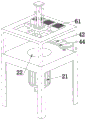
FIG. 2 is a schematic perspective view of the present invention;
FIG. 3 is a front view of the present invention;
FIG. 4 is a schematic perspective view of the present invention trimming moving mechanism and trimming mechanism;
reference numerals:
the trimming mechanism comprises a work frame 1, a trimming rotating mechanism 2, a rotating motor 21, a rotating disc 22, a trimming fixing mechanism 3, a fixed frame 31, a fixed electric cylinder 32, a fixed disc 33, a trimming moving mechanism 4, a moving block 41, a moving screw rod 42, a moving motor 43, a moving slide rail 44, a sliding motor 45, a sliding plate 46, a sliding gear 47, a trimming mechanism 5, a trimming motor 51, a trimming grinding wheel 52, a dust cleaning mechanism 6 and a cleaning fan 61.
Detailed Description
In order to make the objects, technical solutions and advantages of the present invention more apparent, the technical solutions of the present invention will be clearly and completely described below with reference to the specific embodiments of the present invention and the accompanying drawings. It is to be understood that the described embodiments are merely exemplary of the utility model, and not restrictive of the full scope of the utility model. All other embodiments, which can be derived by a person skilled in the art from the embodiments given herein without making any creative effort, shall fall within the protection scope of the present invention.
The utility model provides trimming equipment for a rubber rail lower base plate, which is shown in the following by combining fig. 1 to 4, and comprises a work frame 1, a trimming rotating mechanism 2, a trimming fixing mechanism 3, a trimming moving mechanism 4, a trimming mechanism 5 and a dust cleaning mechanism 6, wherein the trimming rotating mechanism 2 is rotationally connected to the work frame 1, the trimming fixing mechanism 3 is positioned at the top of the work frame 1, the trimming moving mechanism 4 is rotationally connected to the trimming fixing mechanism 3, the trimming mechanism 5 is positioned on the trimming moving mechanism 4, and the dust cleaning mechanism 6 is positioned on the trimming fixing mechanism 3.
Specifically, the trimming and rotating mechanism 2 comprises a rotating motor 21 and a rotating disc 22, a rotating groove is formed in the middle of the work frame 1, the rotating disc 22 is rotatably connected in the rotating groove, the rotating motor 21 is located at the bottom of the work frame 1, and a main shaft of the rotating motor 21 is fixedly connected with the bottom of the rotating disc 22. The trimming fixing mechanism 3 comprises a fixed frame 31, a fixed electric cylinder 32 and a fixed disc 33, wherein the fixed frame 31 is positioned at the top of the fixed frame 31, the fixed electric cylinder 32 is positioned at the top of the fixed frame 31, and the fixed disc 33 is rotatably connected with the telescopic end of the fixed electric cylinder 32. When trimming the position of the backing plate, the telescopic end of the fixed electric cylinder 32 moves downwards to drive the fixed disc 33 to move downwards, the position of the fixed disc 33 is moved to be above the backing plate, the position of the backing plate to be trimmed is fixed, the position of the backing plate is prevented from moving in the trimming process, then the rotating motor 21 works to drive the rotating disc 22 to rotate, the rotating disc 22 rotates to drive the backing plate to rotate on the telescopic end of the fixed electric cylinder 32 through the fixed disc 33, the backing plate can be driven to rotate on the working frame 1, and trimming operation can be carried out on different sides of the backing plate
Specifically, the trimming moving mechanism 4 comprises a moving block 41, a moving lead screw 42, a moving motor 43 and a moving slide rail 44, wherein the moving slide rail 44 is horizontally arranged at the top of the working frame 1, the moving lead screw 42 is rotatably connected to the fixed frame 31, the moving block 41 is in threaded connection with the moving lead screw 42, the bottom of the moving block 41 is in sliding fit with the moving slide rail 44, the moving motor 43 is positioned on the side wall of the fixed frame 31, and the moving motor 43 is in transmission connection with the moving lead screw 42; the trimming moving mechanism 4 further comprises a sliding motor 45, a sliding plate 46 and a sliding gear 47, wherein the bottom of the sliding plate 46 is provided with two sliding blocks, the sliding plate 46 is connected with the moving block 41 in a sliding manner through the two sliding blocks, the sliding motor 45 is fixedly connected to the moving block 41, the sliding gear 47 is connected with a main shaft of the moving motor 43, the bottom of the sliding plate 46 is provided with a tooth groove, and the sliding gear 47 penetrates through the moving block 41 to be meshed with the tooth groove at the bottom of the sliding plate 46; the deburring mechanism 5 comprises a deburring motor 51 and a deburring grinding wheel 52, wherein the deburring motor 51 is positioned on the sliding plate 46, and the deburring grinding wheel 52 is connected with a main shaft of the deburring motor 51. When the base plate is trimmed, the sliding motor 45 works to drive the sliding gear 47 to rotate at the bottom of the sliding plate 46, so that the sliding plate 46 is driven to move on the moving block 41 through the two sliding blocks, the position of the trimming grinding wheel 52 can be moved to the side of the base plate according to the position of the base plate, at the moment, the trimming motor 51 works to drive the trimming grinding wheel 52 to rotate, the burrs generated on the base plate are polished, at the same time of polishing, the moving motor 43 works to drive the moving screw rod 42 to rotate, the moving screw rod 42 rotates to drive the position of the moving block 41 to move on the moving slide rail 44, the moving block 41 moves to drive the position of the trimming grinding wheel 52 to move, and trimming operation is performed on different positions on the base plate.
Specifically, the dust cleaning mechanism 6 includes three cleaning fans 61, and the three cleaning fans 61 are disposed on the fixing frame 31 at equal intervals. The three cleaning fans 61 can clean dust generated by trimming, and pollution to the environment is prevented.
The above description is only an example of the present invention, and is not intended to limit the present invention. Various modifications and alterations to this invention will become apparent to those skilled in the art. Any modification, equivalent replacement, improvement, etc. made within the spirit and principle of the present invention should be included in the scope of the claims of the present invention.
Claims (7)
1. The utility model provides a deburring equipment of rubber rail lower bolster, its characterized in that, includes work frame (1), deburring rotary mechanism (2), deburring fixed establishment (3), deburring moving mechanism (4), deburring mechanism (5) and dust clearance mechanism (6), deburring rotary mechanism (2) rotates to be connected on work frame (1), deburring fixed establishment (3) are located the top of work frame (1), deburring moving mechanism (4) rotate to be connected on deburring fixed establishment (3), deburring mechanism (5) are located deburring moving mechanism (4), dust clearance mechanism (6) are located deburring fixed establishment (3).
2. The apparatus for trimming rubber rail lower tie plate according to claim 1, wherein: trimming rotary mechanism (2) include rotating electrical machines (21) and rotary disk (22), the intermediate position of work frame (1) is equipped with the rotation groove, rotary disk (22) rotate to be connected in the rotation groove, rotating electrical machines (21) are located the bottom of work frame (1), the main shaft of rotating electrical machines (21) and the bottom fixed connection of rotary disk (22).
3. The apparatus for trimming rubber rail lower tie plate according to claim 1, wherein: trimming fixed establishment (3) are including mount (31), fixed electric jar (32) and fixed disk (33), mount (31) are located the top of mount (31), fixed electric jar (32) are located the top of mount (31), fixed disk (33) are connected with the flexible end rotation of fixed electric jar (32).
4. The apparatus for trimming rubber rail lower back plate according to claim 3, wherein: the trimming moving mechanism (4) comprises a moving block (41), a moving screw rod (42), a moving motor (43) and a moving slide rail (44), the moving slide rail (44) is horizontally arranged at the top of the working frame (1), the moving screw rod (42) is rotatably connected to the fixed frame (31), the moving block (41) is in threaded connection with the moving screw rod (42), the bottom of the moving block (41) is in sliding fit with the moving slide rail (44), the moving motor (43) is located on the side wall of the fixed frame (31), and the moving motor (43) is in transmission connection with the moving screw rod (42).
5. The apparatus for trimming rubber rail lower tie plate according to claim 1, wherein: the trimming moving mechanism (4) further comprises a sliding motor (45), a sliding plate (46) and a sliding gear (47), two sliding blocks are arranged at the bottom of the sliding plate (46), the sliding plate (46) is in sliding connection with the moving block (41) through the two sliding blocks, the sliding motor (45) is fixedly connected to the moving block (41), the sliding gear (47) is connected with a main shaft of the moving motor (43), a tooth groove is formed in the bottom of the sliding plate (46), and the sliding gear (47) penetrates through the moving block (41) to be meshed with the tooth groove in the bottom of the sliding plate (46).
6. The apparatus for edging a rubber rail lower bolster plate according to claim 5, characterized in that: the trimming mechanism (5) comprises a trimming motor (51) and a trimming grinding wheel (52), the trimming motor (51) is positioned on the sliding plate (46), and the trimming grinding wheel (52) is connected with a main shaft of the trimming motor (51).
7. The apparatus for trimming rubber rail lower tie plate according to claim 1, wherein: dust clearance mechanism (6) include three clearance fan (61), three clearance fan (61) equidistant setting is on mount (31).
Priority Applications (1)
| Application Number | Priority Date | Filing Date | Title |
|---|---|---|---|
| CN202122517999.5U CN216179206U (en) | 2021-10-19 | 2021-10-19 | Trimming equipment for rubber rail lower base plate |
Applications Claiming Priority (1)
| Application Number | Priority Date | Filing Date | Title |
|---|---|---|---|
| CN202122517999.5U CN216179206U (en) | 2021-10-19 | 2021-10-19 | Trimming equipment for rubber rail lower base plate |
Publications (1)
| Publication Number | Publication Date |
|---|---|
| CN216179206U true CN216179206U (en) | 2022-04-05 |
Family
ID=80884565
Family Applications (1)
| Application Number | Title | Priority Date | Filing Date |
|---|---|---|---|
| CN202122517999.5U Active CN216179206U (en) | 2021-10-19 | 2021-10-19 | Trimming equipment for rubber rail lower base plate |
Country Status (1)
| Country | Link |
|---|---|
| CN (1) | CN216179206U (en) |
-
2021
- 2021-10-19 CN CN202122517999.5U patent/CN216179206U/en active Active
Similar Documents
| Publication | Publication Date | Title |
|---|---|---|
| CN112139887A (en) | Panel grinding device for machining | |
| CN208866965U (en) | A kind of production Ceramic Tiles polissoir | |
| CN211940217U (en) | Fork truck is accurate grinding device for foundry goods | |
| CN209954348U (en) | Grinding device is used in processing of accurate pivot | |
| CN210909323U (en) | Edging device for glass processing | |
| CN212858879U (en) | Be used for full-automatic glass edging device of toughened glass production line | |
| CN216179206U (en) | Trimming equipment for rubber rail lower base plate | |
| CN218837099U (en) | Burr polisher | |
| CN210060687U (en) | Machining center for special-shaped mechanical parts | |
| CN108838470B (en) | Finish machining device for automobile gear | |
| CN213592455U (en) | Grinding device is used in production of indoor lamp shade | |
| CN216066923U (en) | Surface treatment device for processing mobile phone rear shell | |
| CN210756977U (en) | Full-automatic plane grinding device | |
| CN212846383U (en) | Automatic polishing machine for watch case | |
| CN220260404U (en) | Round polisher that two sides were polished | |
| CN214237651U (en) | Metal part surface polishing device | |
| CN210024711U (en) | High-efficient grinding device is used in panel processing | |
| CN214869495U (en) | Office furniture corner polishing mechanism | |
| CN210550434U (en) | Stainless steel backing plate is polished and is used fixing device | |
| CN216371454U (en) | Casting deburring equipment | |
| CN217494650U (en) | Automatic mud blank trimming machine for ceramic hand mold | |
| CN219170407U (en) | Glass edging device capable of cooling water circulation | |
| CN216029866U (en) | Numerical control angle grinding machine for computer box | |
| CN211072980U (en) | A edging equipment for glass processing | |
| CN217493715U (en) | Glass edging device |
Legal Events
| Date | Code | Title | Description |
|---|---|---|---|
| GR01 | Patent grant | ||
| GR01 | Patent grant |