CN216175810U - Fixture mechanism of rim expanding machine - Google Patents
Fixture mechanism of rim expanding machine Download PDFInfo
- Publication number
- CN216175810U CN216175810U CN202122381507.4U CN202122381507U CN216175810U CN 216175810 U CN216175810 U CN 216175810U CN 202122381507 U CN202122381507 U CN 202122381507U CN 216175810 U CN216175810 U CN 216175810U
- Authority
- CN
- China
- Prior art keywords
- lifting
- conical table
- rim
- workbench
- guide post
- Prior art date
- Legal status (The legal status is an assumption and is not a legal conclusion. Google has not performed a legal analysis and makes no representation as to the accuracy of the status listed.)
- Active
Links
Images


Abstract
The utility model provides a clamp mechanism of a rim circle expanding machine, which comprises a circle expanding slide block assembly, a workbench, a conical table and a stretching assembly and is characterized in that T-shaped slide blocks of the circle expanding slide block assembly are uniformly distributed in T-shaped grooves distributed on the workbench in an annular matrix manner, a mold base plate is mounted on each T-shaped slide block, a shaping mold can be mounted on each mold base plate, the conical table is arranged at the center of the shaping mold in an inverted manner, the shaping mold is gathered into a circular shape, a hopper cavity is arranged at the center of the shaping mold and is in sliding fit with the conical surface of the conical table, the stretching assembly is mounted at the bottom of the workbench, and a lifting main shaft of the stretching assembly is connected with the conical table. According to the clamp mechanism of the rim expanding machine, the stretching assembly is arranged at the bottom of the workbench, the clamp is expanded in a pull-down mode, the problem of insufficient precision caused by original stamping and expanding is solved, no obstacle exists above the workbench, and the shaping die and the conical table can be conveniently disassembled and assembled.
Description
Technical Field
The utility model relates to the field of rim production, in particular to a clamping mechanism of a rim expanding machine.
Background
The rim workpiece can deform after the procedures of rolling, welding, aging heat treatment and the like, so that the roundness of a rim product needs to be corrected by a circle expansion procedure, the roundness of the rim is a key index for the rim, the control on the roundness of the rim is generally low in domestic enterprises at present and can only reach 0.8mm, a plurality of enterprises can not meet the production process requirements of middle and high-end bicycle rims, the clamp and the circle expansion power mechanism of the existing circle expansion machine are vertically separated, a hydraulic oil cylinder is adopted for shaping by a stamping and shaping die from top to bottom, the upper center and the lower center of a pressing head and the shaping die are easy to change during each stamping operation, the circle expansion precision is relatively deficient, the operation of the equipment is relatively unstable, the circle expansion effect is not ideal, the qualification rate and the quality of the product need to be improved, and the development of a relatively high-precision rim expansion machine clamp mechanism is urgently needed to improve the roundness shaping precision of the rim product, thereby ensuring the circular runout of the rim, improving the product percent of pass and laying a foundation condition for the industry of the middle and high-end bicycle rims entered by enterprises.
SUMMERY OF THE UTILITY MODEL
The present invention is directed to solving at least one of the problems of the prior art or the related art.
Therefore, the utility model provides a clamp mechanism of a rim expanding machine, which comprises a expanding sliding block assembly, a workbench, a conical table and a stretching assembly, wherein T-shaped sliding blocks of the expanding sliding block assembly are uniformly distributed in T-shaped grooves distributed on the workbench in an annular matrix manner, a mould base plate is arranged on the T-shaped sliding blocks, a shaping mould can be arranged on the mould base plate, the center of the shaping mould is provided with an inverted conical table, the shaping mould is circular after being gathered, a hopper cavity is arranged at the center of the shaping mould and is in sliding fit with the conical surface of the conical table, the stretching assembly is arranged at the bottom of the workbench, and a lifting main shaft of the stretching assembly is connected with the conical table, and the center of the lifting main shaft is positioned on the same central axis.
According to the clamp mechanism of the rim rounding machine, the stretching assembly is arranged at the bottom of the workbench as the power mechanism, the original mode of punching from top to bottom is replaced by the mode of pulling down, the size of equipment is reduced, the refinement of rounding motion is improved, the problem of insufficient precision caused by original punching and rounding is solved, the stretching assembly is arranged below the workbench, only the shaping die and the conical table are arranged on the workbench, no obstacle is arranged above the workbench, and the shaping die and the conical table are convenient to disassemble and assemble.
Preferably, the workbench comprises a bedplate, a round table seat, inserts and threaded pins, wherein the round table seat is arranged on the bedplate and provided with T-shaped grooves distributed in an annular matrix, the round table seat is provided with corresponding inserts below the T-shaped grooves, and the inserts are internally provided with threaded through holes matched with the threaded pins; the table plate is used as a supporting surface of the whole clamp and can be installed on a rack, the circular platform seat is arranged at the center of the table plate and provided with T-shaped grooves distributed in an annular matrix mode and used as a sliding reference of a T-shaped sliding block of the whole expansion sliding block assembly, an insert is arranged below each T-shaped groove, a threaded through hole is formed in each insert and can be used for installing a pressure spring and adjusting the length of the pressure spring, the T-shaped sliding block which slides outwards can retract to the original position after the expansion circular force is removed by the aid of the pressure spring, and a rim product and a next rim product can be conveniently taken out and clamped.
Preferably, the round expansion sliding block assembly further comprises a pressure spring and an L-shaped plate, the bottom of the inner side of the die base plate is fixedly connected with the end face of the inner side of the T-shaped sliding block through the L-shaped plate, a positioning rod is arranged at the lower end of the L-shaped plate, and the pressure spring is sleeved on the positioning rod and the threaded pin; one end of a pressure spring is pressed on the L-shaped plate, the upper portion of the L-shaped plate is connected with the end face of the T-shaped sliding block and the bottom of the inner side of the die base plate, the other end of the pressure spring is pressed on a threaded pin, and the length of the pressure spring is adjusted through the threaded pin so as to be suitable for rim products in different size positions.
Preferably, the stretching assembly further comprises a fixed guide post frame, a lifting guide sleeve, a tangent plane guide sleeve and an oil cylinder, the upper end of the fixed guide post frame is fixedly suspended at the center of the bottom surface of the bedplate, the lifting guide sleeve is arranged on a guide post fixing plate of the fixed guide post frame, the lifting guide post frame is arranged in the lifting guide sleeve in a penetrating manner, two ends of the oil cylinder are respectively fixed between the guide post fixing plate and a lower lifting plate of the lifting guide post, the center of the upper lifting plate of the lifting guide post is fixed with the lifting spindle, the lifting spindle is provided with a tangent plane and matched with the tangent plane guide sleeve, and the upper end of the lifting spindle is connected with the conical table; the fixed guide post frame fixes whole tensile assembly in the bottom surface of workstation, the lift guide post frame is then worn to establish in the lift guide sleeve of the guide pillar fixed plate of fixed guide post frame, the hydro-cylinder promotes lift guide post frame up-and-down motion, and then will fix the lift main shaft up-and-down motion at last lifter plate center, and then drive the toper bench up-and-down motion that links to each other with it, the slip through the toper face realizes the harmomegathus motion of bloated circle slider subassembly level, and then realize the plastic correction to the rim appearance through the working face of plastic mould, the lift main shaft all is equipped with the tangent plane with the lift guide sleeve, avoid the lift main shaft to rotate, be convenient for adjust the initial position of toper platform, in order to satisfy the plastic requirement of different cun position rim products.
Preferably, the conical table is provided with a central threaded through hole and is in threaded fit with the lifting spindle, and the large bottom end of the conical table is provided with a handle; in order to improve the connection reliability of the lifting main shaft and the conical table, the conical table is arranged at the initial position of the conical table conveniently, the conical table is arranged as a central threaded through hole, the upper end of the lifting main shaft is also provided with matched external threads, and the initial height of the conical table can be adjusted by rotating the handle through the threads so as to meet the shaping requirements of rim property rights at different inch positions.
Preferably, the top end of the lifting main shaft is provided with internal threads, and the conical table and the lifting main shaft can be tightly connected through bolts and a pressing plate; after the initial height of the conical table is adjusted, in order to fix the height and avoid loosening or rotating the conical table in production, an internal thread is arranged at the top end of the lifting main shaft, and the conical table and the lifting main shaft are screwed tightly by a pressing plate and a bolt.
Preferably, the outer end of the T-shaped sliding block is also provided with a limiting block; the outer end of the T-shaped sliding block is provided with a limiting block, so that the T-shaped sliding block is prevented from moving in an overtravel manner, and the safety of equipment and personnel is ensured.
Additional aspects and advantages of the utility model will be set forth in part in the description which follows, and in part will be obvious from the description, or may be learned by practice of the utility model.
Drawings
FIG. 1 is a schematic top view of a structure of the present invention;
FIG. 2 is a front view of FIG. 1;
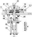
FIG. 3 is a sectional view taken along line B-B of FIG. 1;
the scores in the figures are as follows: the device comprises a circular expansion slider assembly 1, a T-shaped slider 11, a limiting block 111, a die backing plate 12, a shaping die 13, a pressure spring 14, an L-shaped plate 15, a workbench 2, a bedplate 21, a circular truncated cone seat 22, an insert 23, a threaded pin 24, a conical table 3, a handle 31, a stretching assembly 4, a lifting spindle 41, a fixed guide column frame 42, a lifting guide column frame 43, a lifting guide sleeve 44, a tangent plane guide sleeve 45 and an oil cylinder 46.
Detailed Description
In order that the above objects, features and advantages of the present invention can be more clearly understood, a more particular description of the utility model will be rendered by reference to the appended drawings. It should be noted that the embodiments and features of the embodiments of the present application may be combined with each other without conflict.
In the following description, numerous specific details are set forth in order to provide a thorough understanding of the present invention, however, the present invention may be practiced otherwise than as specifically described herein, and thus the scope of the present invention is not limited by the specific embodiments disclosed below.
Some embodiments provided by the present invention are described below with reference to fig. 1 to 3.
The utility model provides a clamp mechanism of a rim circle expanding machine, which comprises a circle expanding sliding block assembly 1, a workbench 2, a conical table 3 and a stretching assembly 4, wherein T-shaped sliding blocks 11 of the circle expanding sliding block assembly 1 are uniformly distributed in T-shaped grooves distributed on the workbench 2 in an annular matrix manner, a mould base plate 12 is installed on the T-shaped sliding blocks 11, a shaping mould 13 can be installed on the mould base plate 12, the inverted conical table 3 is arranged at the center of the shaping mould 13, the shaping mould 13 is gathered into a circular shape, a hopper cavity is arranged at the center and is in sliding fit with the conical surface of the conical table 3, the stretching assembly 4 is installed at the bottom of the workbench 2, and a lifting main shaft 41 of the stretching assembly 4 is connected with the conical table 3, and the center of the lifting main shaft is positioned on the same central axis.
According to the clamp mechanism of the rim rounding machine, the stretching assembly 4 is arranged at the bottom of the workbench 2 as a power mechanism, the original mode of punching from top to bottom is replaced by a mode of pulling down, the size of equipment is reduced, the refinement of rounding motion is improved, the problem of insufficient precision caused by original punching and rounding is solved, the stretching assembly 4 is arranged below the workbench 2, only the shaping die 13 and the conical table 3 are arranged on the workbench 2, no obstacle is arranged above the shaping die 13 and the conical table 3, and the shaping die 13 and the conical table 3 can be conveniently disassembled and assembled.
Preferably, the workbench 2 comprises a bedplate 21, a circular table base 22, inserts 23 and threaded pins 24, the circular table base 22 is arranged on the bedplate 21, the circular table base 22 is provided with T-shaped grooves distributed in an annular matrix, the corresponding inserts 23 are arranged on the circular table base 22 below the T-shaped grooves, and threaded through holes matched with the threaded pins 24 are formed in the inserts 23; the bedplate 21 serves as a supporting surface of the whole clamp and can be installed on a rack, the circular truncated cone seat 22 is arranged at the center of the bedplate 21 and provided with T-shaped grooves distributed in an annular matrix and used as a sliding reference of the T-shaped slider 11 of the whole expansion round slider assembly 1, an insert 23 is arranged below the T-shaped groove, a threaded through hole is formed in the insert 23 and can be used for installing a pressure spring 14 and adjusting a threaded pin 24 of the pressure spring 14, the pressure spring 14 retracts the T-shaped slider 11 which slides outwards after the expansion round force is removed, and a rim product can be taken out and a next rim product can be clamped conveniently.
Preferably, the round expansion sliding block assembly 1 further comprises a pressure spring 14 and an L-shaped plate 15, the bottom of the inner side of the die base plate 12 is fixedly connected with the end face of the inner side of the T-shaped sliding block 11 through the L-shaped plate 15, a positioning rod is arranged at the lower end of the L-shaped plate 15, and the pressure spring 14 is sleeved on the positioning rod and a threaded pin 24; one end of a pressure spring 14 is pressed against an L-shaped plate 15, the upper portion of the L-shaped plate 15 is connected with the end face of the T-shaped sliding block 11 and the bottom of the inner side of the die base plate 12, the other end of the pressure spring 14 is pressed against a threaded pin 24, and the length of the pressure spring 14 is adjusted through the threaded pin 24 so as to be suitable for rim products with different sizes.
Preferably, the stretching assembly 4 further comprises a fixed guide post frame 42, a lifting guide post frame 43, a lifting guide sleeve 44, a tangent plane guide sleeve 45 and an oil cylinder 46, the upper end of the fixed guide post frame 42 is fixed at the center of the bottom surface of the bedplate 21 in a hanging manner, the lifting guide sleeve 44 is arranged on a guide post fixing plate of the fixed guide post frame 42, the lifting guide post frame 43 is arranged in the lifting guide sleeve 44 in a penetrating manner, two ends of the oil cylinder 46 are respectively fixed between the guide post fixing plate and a lower lifting plate of the lifting guide post, the center of the upper lifting plate of the lifting guide post is fixed with the lifting spindle 41, the lifting spindle 41 is provided with a tangent plane and matched with the tangent plane guide sleeve 45, and the upper end of the lifting spindle 41 is connected with the conical table 3; the fixed guide post frame 42 fixes the whole stretching assembly 4 on the bottom surface of the workbench 2, the lifting guide post frame 43 is arranged in a lifting guide sleeve 44 of a guide post fixing plate of the fixed guide post frame 42 in a penetrating mode, the oil cylinder 46 pushes the lifting guide post frame 43 to move up and down, and then the lifting main shaft 41 fixed at the center of the upper lifting plate moves up and down, and further the conical table 3 connected with the lifting guide post frame is driven to move up and down, the expansion and contraction movement of the expansion circular slider assembly 1 in the horizontal direction is achieved through the sliding of the conical surface, and further the shaping correction of the appearance of the rim is achieved through the working surface of the shaping die 13, the lifting main shaft 41 and the lifting guide sleeve 44 are both provided with tangent planes, the rotation of the lifting main shaft 41 is avoided, the initial position of the conical table 3 is convenient to adjust, and the shaping requirements of rim products with different sizes are met.
Preferably, the conical table 3 is provided with a central threaded through hole and is in threaded fit with the lifting spindle 41, and the large bottom end of the conical table 3 is provided with a handle 31; in order to improve the connection reliability of the lifting spindle 41 and the conical table 3 and facilitate the initial position of the conical table 3, the conical table 3 is arranged as a central threaded through hole, the upper end of the lifting spindle 41 is also provided with matched external threads, and the initial height of the conical table 3 can be adjusted by rotating the handle 31 through the threads so as to meet the shaping requirements of rim property rights of different inch positions.
Preferably, the top end of the lifting spindle 41 is provided with internal threads, and the conical table 3 and the lifting spindle 41 can be tightly connected through bolts and a pressure plate; after the initial height of the conical table 3 is adjusted, in order to fix the height and avoid loosening or rotating the conical table 3 in production, an internal thread is formed at the top end of the lifting spindle 41, and the conical table 3 and the lifting spindle 41 are screwed tightly by a pressing plate and a bolt.
Preferably, the outer end of the T-shaped slider 11 is further provided with a limit block 111; the outer end of the T-shaped sliding block 11 is provided with a limiting block 111, so that the T-shaped sliding block 11 is prevented from moving in an overtravel manner, and the safety of equipment and personnel is ensured.
The above is only a preferred embodiment of the present invention, and is not intended to limit the present invention, and various modifications and changes will occur to those skilled in the art. Any modification, equivalent replacement, or improvement made within the spirit and principle of the present invention should be included in the protection scope of the present invention.
Claims (7)
1. A clamp mechanism of a rim round expansion machine comprises a round expansion sliding block component (1), a workbench (2), a conical table (3) and a stretching component (4), it is characterized in that the T-shaped sliding blocks (11) of the expansion sliding block assembly (1) are uniformly distributed in T-shaped grooves which are distributed on the workbench (2) in an annular matrix manner, a die base plate (12) is arranged on the T-shaped sliding block (11), a shaping die (13) can be arranged on the die base plate (12), the center of the shaping die (13) is provided with the inverted conical table (3), the shaping die (13) is round after being gathered, a funnel cavity is arranged at the center of the shaping die and is in sliding fit with the conical surface of the conical table (3), the stretching assembly (4) is installed at the bottom of the workbench (2), and a lifting main shaft (41) of the stretching assembly (4) is connected with the conical table (3) and the center of the lifting main shaft is located on the same central axis.
2. The clamp mechanism of the rim flatting mill according to claim 1, wherein the workbench (2) comprises a bedplate (21), a pedestal (22), an insert (23) and a threaded pin (24), the pedestal (22) is arranged on the bedplate (21), the T-shaped grooves distributed in an annular matrix are arranged on the pedestal (22), the corresponding insert (23) is arranged on the pedestal (22) below the T-shaped grooves, and a threaded through hole matched with the threaded pin (24) is arranged in the insert (23).
3. The rim flatting machine clamp mechanism according to claim 2, wherein the flatting slider assembly (1) further comprises a pressure spring (14) and an L-shaped plate (15), the bottom of the inner side of the die base plate (12) is fixedly connected with the end face of the inner side of the T-shaped slider (11) through the L-shaped plate (15), a positioning rod is arranged at the lower end of the L-shaped plate (15), and the pressure spring (14) is sleeved on the positioning rod and the threaded pin (24).
4. A rim flatting machine gripper mechanism according to claim 3, characterized in that the stretching assembly (4) further comprises a fixed guide post holder (42), a lifting guide post holder (43), a lifting guide sleeve (44), a tangent plane guide sleeve (45) and an oil cylinder (46), the upper end of the fixed guide post frame (42) is suspended and fixed at the center of the bottom surface of the bedplate (21), the lifting guide sleeve (44) is arranged on the guide post fixing plate of the fixed guide post frame (42), the lifting guide post frame (43) is arranged in the lifting guide sleeve (44) in a penetrating way, two ends of the oil cylinder (46) are respectively fixed between the guide post fixing plate and the lower lifting plate of the lifting guide post, the center of an upper lifting plate of the lifting guide post is fixed with the lifting main shaft (41), the lifting main shaft (41) is provided with a tangent plane and matched with the tangent plane guide sleeve (45), the upper end of the lifting main shaft (41) is connected with the conical table (3).
5. The rim rounder clamp mechanism according to claim 4, characterized in that said conical table (3) is provided with a central threaded through hole and is in threaded engagement with said lifting spindle (41), and a handle (31) is provided on the large bottom end of said conical table (3).
6. The rim flatting machine clamp mechanism according to claim 4, characterized in that the top end of the lifting spindle (41) is provided with an internal thread, and the conical table (3) and the lifting spindle (41) can be tightly connected through a bolt and a pressure plate.
7. The clamp mechanism of the rim expanding machine according to claim 4, wherein a limiting block (111) is further arranged on the outer end of the T-shaped sliding block (11).
Priority Applications (1)
| Application Number | Priority Date | Filing Date | Title |
|---|---|---|---|
| CN202122381507.4U CN216175810U (en) | 2021-09-29 | 2021-09-29 | Fixture mechanism of rim expanding machine |
Applications Claiming Priority (1)
| Application Number | Priority Date | Filing Date | Title |
|---|---|---|---|
| CN202122381507.4U CN216175810U (en) | 2021-09-29 | 2021-09-29 | Fixture mechanism of rim expanding machine |
Publications (1)
| Publication Number | Publication Date |
|---|---|
| CN216175810U true CN216175810U (en) | 2022-04-05 |
Family
ID=80928367
Family Applications (1)
| Application Number | Title | Priority Date | Filing Date |
|---|---|---|---|
| CN202122381507.4U Active CN216175810U (en) | 2021-09-29 | 2021-09-29 | Fixture mechanism of rim expanding machine |
Country Status (1)
| Country | Link |
|---|---|
| CN (1) | CN216175810U (en) |
-
2021
- 2021-09-29 CN CN202122381507.4U patent/CN216175810U/en active Active
Similar Documents
| Publication | Publication Date | Title |
|---|---|---|
| US20170209969A1 (en) | Lathe Chuck for Aluminum Alloy Hubs | |
| CN108555125B (en) | Wheel rim valve hole punching device and wheel rim valve hole punching method | |
| CN109702095B (en) | Multi-size self-adaptive steel pipe bending equipment | |
| CN201500890U (en) | Special fixture for rough boring connecting rod small end | |
| CN210820079U (en) | Concrete member forming machine | |
| CN112108602A (en) | Gear forging die and forging process thereof | |
| CN105750365A (en) | Shaping tooling for quenched check ring | |
| CN216175810U (en) | Fixture mechanism of rim expanding machine | |
| EP3882009A1 (en) | Pull rod type vulcanizing machine | |
| CN104816414A (en) | Intelligent hydraulic die adjusting forcing device and use method thereof | |
| CN217223352U (en) | Novel power plant is mould combination for machine-building device | |
| CN214080119U (en) | Portable pneumatic press | |
| CN114012468A (en) | Precision mold machining device and using method thereof | |
| CN113172285A (en) | High-strength nut forming machine and forming method | |
| CN208960724U (en) | The pressing tool of nuclear power safety injection tank end socket | |
| CN220658948U (en) | Hydraulic press for forming cooking bench | |
| CN112091687A (en) | Fixing clamp for numerical control machine tool | |
| CN216176097U (en) | Rim circle expanding machine | |
| CN218873344U (en) | Rim rounding device | |
| CN212610803U (en) | Full-automatic pressure quenching tool for special-shaped driven bevel gear | |
| CN218903102U (en) | High-toughness wire drawing die for processing | |
| CN219335501U (en) | A mould for rings processing | |
| CN111230019A (en) | Special forging and pressing equipment for coal mine hydraulic support cylinder barrel | |
| CN105729068B (en) | The processing method of automobile air conditioner compressor bent axle | |
| CN218692991U (en) | Bearing seat stretching die |
Legal Events
| Date | Code | Title | Description |
|---|---|---|---|
| GR01 | Patent grant | ||
| GR01 | Patent grant |