CN216161663U - A combined leakage circuit breaker with overload protection - Google Patents
A combined leakage circuit breaker with overload protection Download PDFInfo
- Publication number
- CN216161663U CN216161663U CN202121849224.1U CN202121849224U CN216161663U CN 216161663 U CN216161663 U CN 216161663U CN 202121849224 U CN202121849224 U CN 202121849224U CN 216161663 U CN216161663 U CN 216161663U
- Authority
- CN
- China
- Prior art keywords
- fixedly connected
- circuit breaker
- overload protection
- rods
- leakage circuit
- Prior art date
- Legal status (The legal status is an assumption and is not a legal conclusion. Google has not performed a legal analysis and makes no representation as to the accuracy of the status listed.)
- Expired - Fee Related
Links
Images




Landscapes
- Breakers (AREA)
Abstract
The utility model discloses a combined residual current circuit breaker with overload protection, which comprises a base, wherein the left side and the right side of the upper surface of the base are respectively and fixedly connected with first supporting rods, the top ends of the two first supporting rods are respectively and rotatably connected with first limiting plates, the two first limiting plates are respectively in threaded connection with threaded rods, and the bottom ends of the two threaded rods are respectively and fixedly connected with second limiting plates. According to the buffer spring, the telescopic rod, the first limiting block and the second limiting block are arranged, so that the pressure can be well divided through the telescopic rod in the process that the threaded rod drives the third limiting block to move, the service time of the buffer spring is effectively prolonged, in addition, the motor is arranged, the first gear and the second gear can be well driven to rotate through the motor, the position of the threaded rod is driven to change, the threaded rod is prevented from being manually rotated by a worker, then the worker is effectively improved, and the use of the worker is facilitated.
Description
Technical Field
The utility model relates to the technical field of electric leakage circuit breakers, in particular to a combined electric leakage circuit breaker with overload protection.
Background
The leakage circuit breaker is a switch which can automatically act when the leakage current in the circuit exceeds a preset value, the common leakage circuit breaker is divided into a voltage type and a current type, the current type is divided into an electromagnetic type and an electronic type, and the leakage circuit breaker is used for preventing personal electric shock and is selected according to different requirements of direct contact and indirect contact electric shock protection.
Overload protection is overload protection equipment which is additionally arranged for preventing a main power line from being damaged due to overheating caused by overload, and overload is a broader term and can mean that electric equipment is overloaded and also mean that acting force borne by an object is overlarge. Protection against such exceeding of "load" is generally referred to as overload protection, and in a communication power supply system, a function of automatically disconnecting power supply from a power supply device due to an excessive load is referred to as overload protection.
The combination electric leakage circuit breaker who has just opened a kind of area overload protection in chinese patent for CN210668234U, the device sets up the spring direct mount clamp plate of screw rod bottom, thereby let the position that drives spring and clamp plate through the screw rod change, then through clamp plate and casing contact, make inseparabler fastening that casing and base are connected, but when in actual use, because the clamp plate is directly hung by the spring, long-time use leads to the spring to take place deformation easily, then need frequently change the spring, in addition because the screw rod needs staff to manually carry out the rotation adjustment, thereby be unfavorable for staff's use, can not reach the design effect of prediction.
SUMMERY OF THE UTILITY MODEL
The present invention aims to provide a combined residual current circuit breaker with overload protection to solve the problems in the background art.
In order to achieve the purpose, the utility model adopts the following technical scheme:
the utility model provides a take overload protection's combination residual current circuit breaker, includes the base, the first bracing piece of fixedly connected with, two respectively in both sides about the upper surface of base the top of first bracing piece is rotated respectively and is connected with first limiting plate, two first limiting plate is threaded connection respectively has a threaded rod, two the bottom of threaded rod is fixedly connected with second limiting plate, two respectively the bottom of second limiting plate is fixedly connected with buffer spring, two respectively buffer spring's bottom is fixedly connected with third limiting plate, two the common sliding connection in bottom of third limiting plate has the casing, two the top of threaded rod is fixedly connected with rotating mechanism, two respectively the lower surface of first limiting plate is fixedly connected with buffer gear respectively.
As a further improvement scheme of the technical scheme: the rotating mechanism comprises a first gear, the bottom end of the first gear is fixedly connected with the top end of the threaded rod, the first gear is meshed with a second gear, the bottom end of the second gear is fixedly connected with a rotating plate, and the bottom center of the rotating plate is fixedly connected with a motor through a coupler.
As a further improvement scheme of the technical scheme: the left side and the right side of the lower surface of the rotating plate are respectively connected with second supporting rods in a sliding mode through sliding plates, and the bottom ends of the two second supporting rods are respectively fixedly connected with the left side and the right side of the upper surface of the first limiting plate.
As a further improvement scheme of the technical scheme: buffer gear includes two first stoppers, two the top of first stopper respectively with the front and back both sides fixed connection of the lower surface of first limiting plate, two first stopper is rotated through the front and back both sides of first pivot respectively and is connected with the telescopic link, it is a plurality of two liang of relative, a plurality of the bottom of telescopic link is rotated through the second pivot respectively and is connected with the second stopper, and is a plurality of the bottom of second stopper respectively with the upper surface four corners department fixed connection of rotor plate.
As a further improvement scheme of the technical scheme: the telescopic rods are located on the outer side of the buffer spring.
As a further improvement scheme of the technical scheme: the outer walls of the two first supporting rods are coated with high polymer materials respectively.
As a further improvement scheme of the technical scheme: the inside of casing is provided with heat dissipation channel and conducting strip.
As a further improvement scheme of the technical scheme: the top end of the shell is provided with a circuit breaking unit, one side, close to the circuit breaking unit, of the top end of the shell is provided with an overload protector, and the circuit breaking unit is located on the rear side of the overload protector.
As a further improvement scheme of the technical scheme: the front side of the shell is provided with heat dissipation fins, and the outer walls of the heat dissipation fins are coated with flame-retardant materials.
Compared with the prior art, the utility model has the beneficial effects that:
1. by arranging the telescopic rod, the first limiting block and the second limiting block, the pressure can be well divided by the telescopic rod in the process that the threaded rod drives the third limiting block to move, so that the service time of the buffer spring is effectively prolonged, in addition, by arranging the motor, the first gear and the second gear can be well driven to rotate by the motor, so that the position of the threaded rod is driven to change, the threaded rod is prevented from being manually rotated by a worker, the number of workers is effectively increased, and the use of the workers is facilitated;
2. the second support rod is arranged, so that the voltage can be well divided through the second support rod, the output end coupler of the motor is effectively protected, the service time of the motor is effectively prolonged, and the use of workers is facilitated.
Drawings
Fig. 1 is a schematic structural diagram of a combined residual current circuit breaker with overload protection according to the present invention;
fig. 2 is an enlarged schematic structural diagram of a portion a of the combined residual current circuit breaker with overload protection according to the present invention;
fig. 3 is a schematic structural view of a threaded rod part of the combined residual current circuit breaker with overload protection according to the present invention;
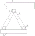
fig. 4 is a schematic structural view of a telescopic rod part of the combined residual current circuit breaker with overload protection according to the present invention;
fig. 5 is a schematic structural diagram of an appearance of a motor of a combined residual current circuit breaker with overload protection according to the present invention;
fig. 6 is a schematic bottom view of a rotating plate of the combined residual current circuit breaker with overload protection according to the present invention.
In the figure: 1. a housing; 2. a first support bar; 3. a first limit plate; 4. a threaded rod; 5. a first gear; 6. a second gear; 7. a third limiting plate; 8. a motor; 9. a telescopic rod; 10. a base; 11. heat dissipation fins; 12. an overload protector; 13. a breaking unit; 14. a rotating plate; 15. a second support bar; 16. a second limiting plate; 17. a buffer spring; 18. a first stopper; 19. and a second limiting block.
Detailed Description
The principles and features of this invention are described below in conjunction with the following drawings, which are set forth by way of illustration only and are not intended to limit the scope of the utility model. The utility model is described in more detail in the following paragraphs by way of example with reference to the accompanying drawings. Advantages and features of the present invention will become apparent from the following description and from the claims. It is to be noted that the drawings are in a very simplified form and are not to precise scale, which is merely for the purpose of facilitating and distinctly claiming the embodiments of the present invention.
It will be understood that when an element is referred to as being "secured to" another element, it can be directly on the other element or intervening elements may also be present. When a component is referred to as being "connected" to another component, it can be directly connected to the other component or intervening components may also be present. When a component is referred to as being "disposed on" another component, it can be directly on the other component or intervening components may also be present. The terms "vertical," "horizontal," "left," "right," and the like as used herein are for illustrative purposes only.
Unless defined otherwise, all technical and scientific terms used herein have the same meaning as commonly understood by one of ordinary skill in the art to which this invention belongs. The terminology used in the description of the utility model herein is for the purpose of describing particular embodiments only and is not intended to be limiting of the utility model. As used herein, the term "and/or" includes any and all combinations of one or more of the associated listed items.
Referring to fig. 1 to 6, in an embodiment of the present invention, a combined residual current circuit breaker with overload protection includes a base 10, first supporting rods 2 are respectively and fixedly connected to left and right sides of an upper surface of the base 10, first limiting plates 3 are respectively and rotatably connected to top ends of the two first supporting rods 2, threaded rods 4 are respectively and threadedly connected to the two first limiting plates 3, second limiting plates 16 are respectively and fixedly connected to bottom ends of the two threaded rods 4, buffer springs 17 are respectively and fixedly connected to bottom ends of the two second limiting plates 16, third limiting plates 7 are respectively and fixedly connected to bottom ends of the two buffer springs 17, a housing 1 is jointly and slidably connected to bottom ends of the two third limiting plates 7, rotating mechanisms are respectively and fixedly connected to top ends of the two threaded rods 4, and buffer mechanisms are respectively and fixedly connected to lower surfaces of the two first limiting plates 3, and can be well limited by the threaded rods 4.
Referring to fig. 1 and 2, the rotating mechanism includes a first gear 5, a bottom end of the first gear 5 is fixedly connected to a top end of the threaded rod 4, the first gear 5 is engaged with a second gear 6, a rotating plate 14 is fixedly connected to a bottom end of the second gear 6, a motor 8 is fixedly connected to a center of a bottom end of the rotating plate 14 through a coupling, and the rotating plate 14 can be rotated well through the motor 8.
Referring to fig. 2, the left and right sides of the lower surface of the rotating plate 14 are slidably connected with second support rods 15 through sliding plates, and the bottom ends of the two second support rods 15 are fixedly connected with the left and right sides of the upper surface of the first limiting plate 3, so that partial pressure can be well divided through the second support rods 15.
Please refer to fig. 3 and fig. 2, the buffering mechanism includes two first limiting blocks 18, the top ends of the two first limiting blocks 18 are respectively fixedly connected with the front and rear sides of the lower surface of the first limiting plate 3, the two first limiting blocks 18 are respectively rotatably connected with the telescopic rods 9 through the front and rear sides of the first rotating shaft, the plurality of telescopic rods 9 are two-by-two opposite, the bottom ends of the plurality of telescopic rods 9 are respectively rotatably connected with the second limiting blocks 19 through the second rotating shaft, the bottom ends of the plurality of second limiting blocks 19 are respectively fixedly connected with the four corners of the upper surface of the rotating plate 14, and the telescopic rods 9 can be well connected through the second limiting blocks 19.
Referring to fig. 1 and 2, the plurality of telescopic rods 9 are located outside the buffer spring 17, and the stress on the buffer spring 17 can be reduced by the telescopic rods 9.
In addition, the outer walls of the two first supporting rods 2 are coated with high polymer materials respectively, and the first limiting plate 3 can be well supported by the first supporting rods 2.
It should be noted that the inside of the housing 1 is provided with a heat dissipation channel and a heat conduction sheet, and heat can be dissipated through the heat conduction sheet well.
Referring to fig. 1, a circuit breaking unit 13 is disposed at a top end of a housing 1, an overload protector 12 is disposed at a side of the top end of the housing 1 close to the circuit breaking unit 13, and the circuit breaking unit 13 is disposed at a rear side of the overload protector 12, so that the circuit can be broken well and timely by the circuit breaking unit 13.
It is worth mentioning that the front side of the housing 1 is provided with the heat dissipating fins 11, and the outer walls of the heat dissipating fins 11 are coated with the flame retardant material, so that heat can be dissipated through the heat dissipating fins 11.
The working principle of the utility model is as follows:
in actual use, firstly, rotate the first limiting plate 3 on the first supporting rod 2 to a suitable position, then the motor 8 starts to work to drive the rotating plate 14 and the second gear 6 to start rotating, meanwhile, the second supporting rod 15 slides below the rotating plate 14, the second gear 6 drives the first gear 5 to rotate, thereby driving the position change of the threaded rod 4 and the second limiting plate 16, the second limiting plate 16 presses the shell 1 through the third limiting plate 7 at the bottom end of the buffer spring 17, thereby the shell 1 and the base 10 are contacted with each other more tightly, in the process, the telescopic rod 9 below the first limiting plate 18 starts to stretch and retract through the second limiting plate 19 correspondingly, and the circuit breaking unit 13 and the overload protector 12 start to work under the condition that circuit breaking is needed, and better heat dissipation is realized through the heat dissipation fins 11 in the working process.
Although the present invention has been described in detail with reference to the foregoing embodiments, it will be apparent to those skilled in the art that various changes in the embodiments and/or modifications of the utility model can be made, and equivalents and modifications of some features of the utility model can be made without departing from the spirit and scope of the utility model.
Claims (9)
Priority Applications (1)
| Application Number | Priority Date | Filing Date | Title |
|---|---|---|---|
| CN202121849224.1U CN216161663U (en) | 2021-08-09 | 2021-08-09 | A combined leakage circuit breaker with overload protection |
Applications Claiming Priority (1)
| Application Number | Priority Date | Filing Date | Title |
|---|---|---|---|
| CN202121849224.1U CN216161663U (en) | 2021-08-09 | 2021-08-09 | A combined leakage circuit breaker with overload protection |
Publications (1)
| Publication Number | Publication Date |
|---|---|
| CN216161663U true CN216161663U (en) | 2022-04-01 |
Family
ID=80837992
Family Applications (1)
| Application Number | Title | Priority Date | Filing Date |
|---|---|---|---|
| CN202121849224.1U Expired - Fee Related CN216161663U (en) | 2021-08-09 | 2021-08-09 | A combined leakage circuit breaker with overload protection |
Country Status (1)
| Country | Link |
|---|---|
| CN (1) | CN216161663U (en) |
-
2021
- 2021-08-09 CN CN202121849224.1U patent/CN216161663U/en not_active Expired - Fee Related
Similar Documents
| Publication | Publication Date | Title |
|---|---|---|
| CN211600010U (en) | Circuit breaker mounting rack | |
| CN114204531A (en) | Combined low-voltage surge protector | |
| CN207818488U (en) | A kind of breaker wall surface mounting support | |
| CN117691488A (en) | A protective operating box mounting bracket | |
| CN210577240U (en) | Transformer substation parallel capacitor protection device | |
| CN113193486B (en) | An isolating switch for an inflatable switch cabinet | |
| CN213602237U (en) | An integrated control cabinet | |
| CN211376546U (en) | Drawer type low-voltage circuit breaker with connecting device | |
| CN216353833U (en) | Control and protection switch | |
| CN210246023U (en) | Electric appliance control cabinet convenient to automatically dissipate heat | |
| CN213185060U (en) | High-efficient radiating high-pressure inlet wire cabinet | |
| CN212011802U (en) | Heat dissipation distribution box for electrical engineering | |
| CN215185428U (en) | Wall-hanging switch board | |
| CN220985216U (en) | Switch cabinet with heat radiation structure | |
| CN117832023B (en) | Breaker mounting rack | |
| CN222029819U (en) | Protective flat-plate type switching power supply | |
| CN217694051U (en) | Electronic equipment shell | |
| CN209747424U (en) | A plastic case circuit breaker | |
| CN217281735U (en) | A surge-proof AC low-voltage switch cabinet | |
| CN218828425U (en) | Undervoltage protection device for power distribution cabinet | |
| CN215299152U (en) | A new type of DC circuit breaker | |
| CN214849928U (en) | Low-voltage comprehensive power distribution switch cabinet | |
| CN216529849U (en) | Miniaturized isolating circuit breaker switch cabinet | |
| CN215453509U (en) | Industry DC power module protective housing with dustproof heat dissipation function | |
| CN214100530U (en) | High-low voltage complete switch equipment with protective structure |
Legal Events
| Date | Code | Title | Description |
|---|---|---|---|
| GR01 | Patent grant | ||
| GR01 | Patent grant | ||
| CF01 | Termination of patent right due to non-payment of annual fee |
Granted publication date: 20220401 |
|
| CF01 | Termination of patent right due to non-payment of annual fee |