CN216147003U - Ventilation structure of wisdom chicken farm - Google Patents
Ventilation structure of wisdom chicken farm Download PDFInfo
- Publication number
- CN216147003U CN216147003U CN202121749845.2U CN202121749845U CN216147003U CN 216147003 U CN216147003 U CN 216147003U CN 202121749845 U CN202121749845 U CN 202121749845U CN 216147003 U CN216147003 U CN 216147003U
- Authority
- CN
- China
- Prior art keywords
- screen
- motor
- shell
- wall
- ventilation structure
- Prior art date
- Legal status (The legal status is an assumption and is not a legal conclusion. Google has not performed a legal analysis and makes no representation as to the accuracy of the status listed.)
- Active
Links
Images


Landscapes
- Filtering Of Dispersed Particles In Gases (AREA)
Abstract
The utility model provides a ventilation structure of an intelligent chicken farm, and relates to the technical field of cultivation ventilation. This kind of ventilation structure in wisdom chicken farm starts first motor through control switch and lets the dwang drive the screen cloth and rotate, makes the density between the screen cloth diminish, lets filterable effect can be better.
Description
Technical Field
The utility model relates to the technical field of cultivation ventilation, in particular to a ventilation structure for a chicken farm.
Background
The ventilation of the chicken farm is an important technical process, and the good ventilation design not only provides comfortable environmental conditions for chickens, improves the health level and production level of chicken flocks and reduces the occurrence of diseases, but also can reduce the feeding management cost, thereby achieving the effect of achieving twice the result with half the effort for the production of the chicken farm;
the mode that the ventilation mode among the prior art passes through the screen cloth intercepts the impurity in the air, but because some impurity are less in the air, the screen cloth makes some impurity can not filter the target in place for fixed connected mode mostly moreover, lets the screen cloth take place to block up easily when piling up too much impurity on the screen cloth simultaneously, makes the gas outlet take place to block up and leads to can not ventilate, consequently solves above problem and provides the ventilation structure in wisdom chicken farm.
SUMMERY OF THE UTILITY MODEL
The utility model aims to solve the defects in the background art and provides a ventilation structure of an intelligent chicken farm.
In order to achieve the purpose, the utility model provides the following technical scheme that the ventilation structure of the intelligent chicken farm comprises a shell, a control switch and a limiting component;
an air inlet is formed in the outer surface of one end of the shell, a control switch is arranged on the outer surface of the periphery of the shell, an air outlet is formed in the outer surface of the other end of the shell, and a screen is movably connected to the inner wall of the shell;
the inner wall embedding of shell is provided with spacing subassembly for carry on spacingly to the screen cloth.
As a further description of the above technical solution: the limiting assembly comprises a movable groove, a pulley, a compression spring and a screen, the movable groove is formed in the inner wall of the shell in an embedded mode, the pulley is connected to the inner wall of the movable groove in a sliding mode, the compression spring is movably connected to one side face of the pulley, and the screen is fixedly connected to one end of the compression spring.
As a further description of the above technical solution: the bottom fixedly connected with "U" shape baffle of screen cloth, the top surface embedding of baffle is provided with the entry, the inner wall fixedly connected with adsorbed layer of baffle, the baffle is close to one side embedding of screen cloth and is provided with the clearance hole, the inner wall in clearance hole is provided with the cleaning brush, and the cleaning brush sets up for the slope, the one end of cleaning brush closely pastes with the surperficial close phase of screen cloth.
As a further description of the above technical solution: a side fixedly connected with dwang of screen cloth, the one end swing joint of dwang has first motor, the surface of first motor is equipped with the draw runner, one side sliding connection of draw runner has the activity groove, the one end of activity groove is equipped with fixed frame, the activity trench is located the inner wall of fixed frame.
As a further description of the above technical solution: the bottom surface of first motor is connected with the gyro wheel, the periphery of gyro wheel is equipped with the semicircle rubber piece, and the rubber piece closely pastes with the bottom surface of first motor closely, the surface of shell is connected with the second motor, second motor one side drive is connected with the roller bearing, the one end and the roller bearing fixed connection of gyro wheel, and control switch and second motor electric connection.
As a further description of the above technical solution: the shell is divided into a left part and a right part, and the left part and the right part are connected through a fixing plate.
The utility model provides a ventilation structure of an intelligent chicken farm, which has the following beneficial effects:
1. the utility model has the advantages of, in getting into the shell through the air intake, start first motor through control switch and let the dwang drive the screen cloth and rotate, make the density between the screen cloth can diminish, let filterable effect can be better.
2. Secondly, drive the clearance hole through the baffle when the screen cloth rotates and let inside clearance brush sweep the surface of screen cloth and collect in flowing into the baffle through the clearance hole with the impurity on screen cloth surface, make the rubbish on the screen cloth be convenient for clear up.
Drawings
Fig. 1 is a schematic view of the overall structure of the present invention.
Fig. 2 is a schematic cross-sectional view of the overall structure of the present invention.
Fig. 3 is an enlarged view of fig. 2A of the present invention.
Fig. 4 is a schematic view of the overall structure of the screen mesh of the present invention.
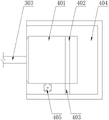
Fig. 5 is a schematic view of the internal connection structure of the fixing frame according to the present invention.
In FIGS. 1-5: 1. a housing; 101. an air inlet; 102. a control switch; 103. an air outlet; 104. a fixing plate; 201. a movable groove; 202. a pulley; 203. a compression spring; 204. screening a screen; 3. a baffle plate; 301. An inlet; 302. an adsorption layer; 303. cleaning the holes; 304. cleaning a brush; 4. rotating the rod; 401. a first motor; 402. a slide bar; 403. a movable groove; 404. a fixing frame; 405. and a roller.
Detailed Description
Example (b):
referring to figures 1-5 of the drawings,
the ventilation structure of the intelligent chicken farm provided by the embodiment comprises a shell 1, a control switch 102 and a limiting component;
an air inlet 101 is formed in the outer surface of one end of the shell 1, a control switch 102 is arranged on the outer surface of the periphery of the shell 1, an air outlet 103 is formed in the outer surface of the other end of the shell 1, and a screen 204 is movably connected to the inner wall of the shell 1;
the inner wall embedding of shell 1 is provided with spacing subassembly for carry on spacingly to screen cloth 204.
The PJ series coal-based activated carbon has extremely strong adsorption capacity on organic matters, free chlorine and harmful gases in air in various water-coal-based broken activated carbons, so that the adsorption layer 302 has strong adsorption capacity on impurities mixed in the air, and the impurities are not easy to separate from the baffle 3;
meanwhile, the adsorption layer 302 can also be made of activated carbon, but the single activated carbon is low in speed and low in efficiency, the admixture is ash which is an inorganic part of the activated carbon and is composed of elements of several activated carbons, secondary pollution is easy to cause, the use limitation is strong, the activated carbon desulfurization device can only be suitable for the conditions of light pollution and good ventilation, the adsorption capacity of the activated carbon is easy to deteriorate when the impurities enter the baffle 3 are excessive, the impurities are separated to the outside of the baffle 3 to block the screen 204 again, and therefore the coal crushing activated carbon is selected as the material of the adsorption layer 302
Further, spacing subassembly includes the activity groove 201, the pulley 202, compression spring 203, screen cloth 204, the inner wall embedding of shell 1 is provided with activity groove 201, the inner wall sliding connection of activity groove 201 has pulley 202, a side swing joint of pulley 202 has compression spring 203, compression spring 203's one end fixedly connected with screen cloth 204, it can carry out steady rotation in the inside of activity groove 201 to drive pulley 202 through screen cloth 204, it breaks away from to be difficult to take place with activity groove 201 when letting screen cloth 204 rotate, can let pulley 202 drive screen cloth 204 shake from top to bottom in the inside of activity groove 201 through compression spring 203 simultaneously, the impurity of the adhesion on messenger's screen cloth 204 can shake and fall down and flow into in baffle 3 through entry 301.
Furthermore, a U-shaped baffle 3 is fixedly connected to one side of the bottom end of the screen 204, an inlet 301 is embedded in the top surface of the baffle 3, an adsorption layer 302 is fixedly connected to the inner wall of the baffle 3, a cleaning hole 303 is embedded in one side of the baffle 3 close to the screen 204, a cleaning brush 304 is arranged on the inner wall of the cleaning hole 303, the cleaning brush 304 is arranged in an inclined manner, one end of the cleaning brush 304 is closely attached to the surface of the screen 204, the screen 204 is limited by the baffle 3, the screen 204 is prevented from being deviated left and right during rotation to be separated from the movable groove 201, the screen 204 is inclined to cause the air filtering not to be in place, meanwhile, falling impurities on the surface of the screen 204 can flow into the baffle 3 through the inlet 301, and the cleaning hole 303 can drive the cleaning brush 304 to sweep the surface of the screen 204 while the screen 204 rotates to cause the impurities on the surface of the screen 204 to flow into the baffle 3 through the cleaning hole 303, and the impurities are adsorbed on the inner wall of the baffle plate 3 through the adsorption layer 302, so that the impurities are not easy to separate out of the baffle plate 3.
Further, a side fixedly connected with dwang 4 of screen cloth 204, the one end swing joint of dwang 4 has first motor 401, the surface of first motor 401 is equipped with draw runner 402, one side sliding connection of draw runner 402 has activity groove 403, the one end of activity groove 403 is equipped with fixed frame 404, activity groove 403 is located the inner wall of fixed frame 404, can let dwang 4 drive screen cloth 204 carry out steady rotation through activity groove 201 through starting first motor 401, make the density on screen cloth 204 surface little, can intercept the impurity of mixing in the gas when flowing, let first motor 401 have sufficient support capacity when rotating through draw runner 402 simultaneously, be difficult to take place to break away from with fixed frame 404, and can let that first motor 401 is steady reciprocate in fixed frame 404.
Further, the bottom surface of the first motor 401 is connected with a roller 405, a semicircular rubber block is arranged on the periphery of the roller 405, the rubber block is tightly attached to the bottom surface of the first motor 401, the outer surface of the housing 1 is connected with a second motor, one side of the second motor is connected with a roller in a driving mode, one end of the roller 405 is fixedly connected with the roller, the control switch is electrically connected with the second motor, the second motor is started through the control switch 102 to enable the roller 405 to rotate, so that the rubber block on the periphery of the roller 405 can prop against the bottom end of the first motor 401, the first motor 401 can move up and down on the inner wall of the fixing frame 404 through the sliding strip 402, the first motor 401 drives the screen 204 to shake up and down in the movable groove 201 through the rotating rod 4, impurities on the surface of the screen 204 can fall off, and the screen 204 is not prone to blocking.
Further, the shell 1 is divided into a left part and a right part, the left part and the right part of the shell 1 are connected through the fixing plate 104, the shell 1 is convenient to detach through the fixing plate 104, and the impurities in the baffle 3 are convenient to operate when needing to be cleaned.
When the device is used, gas flows into the shell 1 through the air inlet 101 to be purified, then impurities in the gas are intercepted through the screen 204 to be filtered, then the first motor 401 is started through the control switch 102, the rotating rod 4 can drive the screen 204 to stably rotate through the movable groove 201, the density of the surface of the screen 204 is smaller, the impurities mixed in the gas can be intercepted while the gas flows, meanwhile, the first motor 401 has enough supporting capacity when rotating through the sliding strip 402, the first motor 401 is not easy to separate from the fixed frame 404, the first motor 401 can stably move up and down in the fixed frame 404, then the screen 204 is limited through the baffle 3, the screen 204 is prevented from being separated from the movable groove 201 due to left and right deviation when rotating, the screen 204 is inclined to cause that the air filtering is not in place, meanwhile, falling impurities on the surface of the screen 204 can flow into the baffle 3 through the inlet 301, the cleaning holes 303 can drive the cleaning brush 304 to sweep the surface of the screen 204 while the screen 204 rotates, the impurities on the surface of the screen 204 flow into the baffle 3 through the cleaning holes 303, the impurities are adsorbed on the inner wall of the baffle 3 through the adsorption layer 302, so that the impurities are not easy to separate out of the baffle 3, then the second motor is started through the control switch 102, the roller 405 rotates to enable the rubber block on the periphery of the roller 405 to push against the bottom end of the first motor 401, the first motor 401 can move up and down on the inner wall of the fixed frame 404 through the sliding strip 402, the first motor 401 drives the screen 204 to shake up and down in the movable groove 201 through the rotating rod 4, so that the impurities on the surface of the screen 204 can fall into the baffle 3, and the screen 204 is not easy to block, and finally, the shell 1 is disassembled through the fixing plate 104 to divide the shell 1 into two parts, so that the impurities in the inner baffle 3 can be conveniently cleaned by workers.
Claims (6)
1. A ventilation structure of an intelligent chicken farm is characterized by comprising a shell, a control switch and a limiting component;
an air inlet is formed in the outer surface of one end of the shell, a control switch is arranged on the outer surface of the periphery of the shell, an air outlet is formed in the outer surface of the other end of the shell, and a screen is movably connected to the inner wall of the shell;
the inner wall embedding of shell is provided with spacing subassembly for carry on spacingly to the screen cloth.
2. The ventilation structure of wisdom chicken farm of claim 1, characterized in that, spacing subassembly includes activity groove, pulley, compression spring, screen cloth, the inner wall embedding of shell is provided with the activity groove, the inner wall sliding connection of activity groove has the pulley, a side swing joint of pulley has compression spring, compression spring's one end fixedly connected with screen cloth.
3. The ventilation structure of the intelligent chicken farm as claimed in claim 1 or 2, wherein a U-shaped baffle is fixedly connected to the bottom end of the screen, an inlet is embedded in the top surface of the baffle, an adsorption layer is fixedly connected to the inner wall of the baffle, a cleaning hole is embedded in one side of the baffle close to the screen, a cleaning brush is arranged on the inner wall of the cleaning hole, the cleaning brush is arranged in an inclined manner, and one end of the cleaning brush is closely attached to the surface of the screen.
4. The ventilation structure of intelligent chicken farm according to claim 1, wherein a rotating rod is fixedly connected to one side of the screen, a first motor is movably connected to one end of the rotating rod, a sliding strip is arranged on the surface of the first motor, a movable groove is slidably connected to one side of the sliding strip, a fixed frame is arranged at one end of the movable groove, and the movable groove is located on the inner wall of the fixed frame.
5. The ventilation structure of intelligent chicken farm as claimed in claim 4, wherein the bottom of the first motor is connected with a roller, the roller is provided with a semi-circular rubber block on its periphery, the rubber block is closely attached to the bottom of the first motor, the outer surface of the housing is connected with a second motor, one side of the second motor is connected with a roller, one end of the roller is fixedly connected with the roller, and the control switch is electrically connected with the second motor.
6. The ventilation structure of intelligent chicken farm as claimed in claim 1, wherein the housing is divided into left and right parts, and the left and right parts are connected by a fixing plate.
Priority Applications (1)
| Application Number | Priority Date | Filing Date | Title |
|---|---|---|---|
| CN202121749845.2U CN216147003U (en) | 2021-07-29 | 2021-07-29 | Ventilation structure of wisdom chicken farm |
Applications Claiming Priority (1)
| Application Number | Priority Date | Filing Date | Title |
|---|---|---|---|
| CN202121749845.2U CN216147003U (en) | 2021-07-29 | 2021-07-29 | Ventilation structure of wisdom chicken farm |
Publications (1)
| Publication Number | Publication Date |
|---|---|
| CN216147003U true CN216147003U (en) | 2022-04-01 |
Family
ID=80837695
Family Applications (1)
| Application Number | Title | Priority Date | Filing Date |
|---|---|---|---|
| CN202121749845.2U Active CN216147003U (en) | 2021-07-29 | 2021-07-29 | Ventilation structure of wisdom chicken farm |
Country Status (1)
| Country | Link |
|---|---|
| CN (1) | CN216147003U (en) |
-
2021
- 2021-07-29 CN CN202121749845.2U patent/CN216147003U/en active Active
Similar Documents
| Publication | Publication Date | Title |
|---|---|---|
| CN114233611A (en) | Compressor air filter element | |
| CN216147003U (en) | Ventilation structure of wisdom chicken farm | |
| CN213912871U (en) | Environmental sanitation dust collecting equipment of green energy-conserving noise reduction | |
| CN113750683A (en) | Active coke flue gas purification and adsorption device | |
| CN210824508U (en) | Organosilicon dust absorbing device | |
| CN211486929U (en) | Roots blower filter equipment | |
| CN217092655U (en) | Waste gas treatment device for roasting furnace for lithium iron phosphate production | |
| CN216767598U (en) | Exhaust gas circulation unit and exhaust gas circulation valve of internal combustion engine | |
| CN211825160U (en) | Particulate matter collection device for atmosphere pollution detection | |
| CN211098043U (en) | Automatic cleaning device for preventing exhaust valve of pantograph from being blocked by wind power | |
| CN209326008U (en) | It is a kind of to divide smoke machine with dedusting function | |
| CN210332011U (en) | Bag-type dust collector | |
| CN209348280U (en) | A kind of construction site cleaner | |
| CN217449357U (en) | Dust remover for metallurgical furnace burden production | |
| CN211202222U (en) | Novel filter for pump | |
| CN210597152U (en) | Special dust absorption fan for dust absorption vehicle | |
| CN216572090U (en) | Desulfurization equipment blower with filtering system | |
| CN214468226U (en) | Haze street lamp is removed to water | |
| CN215742788U (en) | Odor device for urban organic garbage treatment | |
| CN217401192U (en) | Filter type energy-saving ventilation centrifugal fan | |
| CN216728185U (en) | Wind-force dry process coal picker | |
| CN217247516U (en) | Catalytic combustion waste gas treatment device | |
| CN219559002U (en) | Multi-layer type air filtering device | |
| CN212525355U (en) | Anhydrous raise dust processing apparatus for building engineering | |
| CN218238423U (en) | Energy-conserving dust arrester installation of kiln tail |
Legal Events
| Date | Code | Title | Description |
|---|---|---|---|
| GR01 | Patent grant | ||
| GR01 | Patent grant |