CN216138691U - Automobile parts grinding device convenient to angle regulation - Google Patents
Automobile parts grinding device convenient to angle regulation Download PDFInfo
- Publication number
- CN216138691U CN216138691U CN202121946892.6U CN202121946892U CN216138691U CN 216138691 U CN216138691 U CN 216138691U CN 202121946892 U CN202121946892 U CN 202121946892U CN 216138691 U CN216138691 U CN 216138691U
- Authority
- CN
- China
- Prior art keywords
- fixedly connected
- wall
- workbench
- device convenient
- rod
- Prior art date
- Legal status (The legal status is an assumption and is not a legal conclusion. Google has not performed a legal analysis and makes no representation as to the accuracy of the status listed.)
- Active
Links
Images


Abstract
The utility model discloses a polishing device convenient for angle adjustment for automobile parts, which comprises a workbench, wherein a moving mechanism is arranged at the top of the workbench, a hydraulic rod is installed on the moving mechanism, a first motor is fixedly connected to one end of a piston rod of the hydraulic rod, a first fixed disk is fixedly connected to one end of an output shaft of the first motor, a fixed rod is fixedly connected to the middle of the outer wall of the bottom of the first fixed disk, a second rotating ball is fixedly connected to one end of the fixed rod, a first rotating ball seat is fixedly connected to the outer wall of the bottom of the first fixed disk, a first rotating ball is rotatably connected to the inside of the first rotating ball seat, and an electric telescopic rod is fixedly connected to the outer wall of the first rotating ball. The electric telescopic rods are arranged, and the extension and the shortening of the four electric telescopic rods can enable the second fixed disc to rotate around the second rotating ball, so that the polishing disc can be adjusted in multiple directions.
Description
Technical Field
The utility model relates to the technical field of automobile part production, in particular to a polishing device for automobile parts, which is convenient for angle adjustment.
Background
In the process of machining automobile parts, the phenomenon that the surfaces of some metal parts are unsmooth and uneven on the more or less cross sections of the cut metal parts can occur, and the metal parts can greatly influence the subsequent machining production, so that a grinding device is required to grind the metal parts.
Through the retrieval, chinese patent application number is CN 111451908A's patent, discloses a polishing device for automobile parts convenient to angle regulation, relates to automobile parts production technical field, including the base, be equipped with translation mechanism on the roof, remove the bottom one end fixed connection connecting seat of seat, the bottom other end of removing the seat rotates connects electric telescopic handle, the bottom fixed connection second driving motor of fixed plate, the output shaft fixed connection dwang that second drive bottom plate reached, the bottom fixed connection head of polishing of dwang, the top of base is rotated and is connected the rotation seat, and the seat is placed to the coaxial fixed connection in top of rotating the seat, places and is equipped with on the seat and presss from both sides tight fixing device.
Through setting up translation mechanism and fourth drive motor can realize the ascending position control of horizontal direction in the above-mentioned patent, can make the head of polishing slope through setting up connecting seat and electric telescopic handle to realize that omnidirectional sending out is polished, but its head of polishing can only incline in a direction, and it is still not nimble enough.
SUMMERY OF THE UTILITY MODEL
The utility model aims to provide a polishing device for automobile parts, which is convenient for angle adjustment and aims to solve the problems in the background technology.
In order to achieve the purpose, the utility model adopts the following technical scheme:
a polishing device for automobile parts convenient for angle adjustment comprises a workbench, a moving mechanism is arranged at the top of the workbench, a hydraulic rod is arranged on the moving mechanism, one end of a piston rod of the hydraulic rod is fixedly connected with a first motor, one end of an output shaft of the first motor is fixedly connected with a first fixed disc, the middle part of the outer wall of the bottom of the first fixed disc is fixedly connected with a fixed rod, one end of the fixed rod is fixedly connected with a second rotary ball, the outer wall of the bottom of the first fixed disk is fixedly connected with ball seats which are distributed in a rectangular shape, the interior of the ball seat is rotatably connected with a first rotating ball, the outer wall of the first rotating ball is fixedly connected with an electric telescopic rod, one end of a piston rod of the electric telescopic rod is hinged with a second fixed disk, the second fixed disk and the second rotary ball form rotary fit, the middle part of the outer wall of the bottom of the fixed disc II is fixedly connected with a motor, and one end of an output shaft of the motor is fixedly connected with a polishing disc.
Furthermore, the moving mechanism comprises a U-shaped frame fixedly connected to the workbench, a mounting groove is formed in the outer wall of the top of the U-shaped frame, the inner walls of the two sides of the mounting groove are jointly connected with a lead screw through a bearing, a motor II for driving the lead screw to rotate is fixedly connected to the outer wall of one side of the U-shaped frame, a moving block is connected to the outer wall of the lead screw through threads, and the moving block is fixedly connected with the hydraulic rod.
Furthermore, the inner wall of the mounting groove is provided with a slide rail, the outer wall of the moving block is fixedly connected with a slide block, and the slide rail and the slide block form sliding fit.
Furthermore, the outer wall of the top of the workbench is fixedly connected with a dust baffle plate, and the dust baffle plate is U-shaped.
Furthermore, a rectangular groove is formed in the workbench, dust suction holes distributed at equal intervals are formed in the top of the workbench, and the dust suction holes are communicated with the rectangular groove.
Further, an air pump is installed inside the workbench, and the input end of the air pump is communicated with the rectangular groove.
Furthermore, the inside fixedly connected with division board of rectangular channel, the division board divide into negative pressure chamber and the water cavity that distributes from top to bottom with the rectangular channel, the negative pressure chamber is linked together with the input of air pump, the water cavity is linked together with the output of air pump, the output of air pump is located the bottom in water cavity.
Compared with the prior art, the utility model has the beneficial effects that:
1. this a grinding device for automobile parts for being convenient for angle regulation, through being provided with electric telescopic handle, four electric telescopic handle's extension and shortening can make two fixed disks rotate around two ball rotations to make the multi-direction regulation of dish of polishing, motor one can drive the dish of polishing and rotate the regulation, can make the diversified regulation of dish of polishing like this, the flexibility is better.
2. This a grinding device for automobile parts for being convenient for angle regulation, through being provided with the air pump, the air pump can make and produce the negative pressure in the air cavity, makes the dust absorption hole produce suction, adsorbs the dust that grinds the production, and the dust after adsorbing will be followed the output of air pump and inputed the water cavity, mixes with water and collects.
The foregoing description is only an overview of the technical solutions of the present invention, and in order to make the technical solutions of the present invention more clearly understood and to implement them in accordance with the contents of the description, the following detailed description is given with reference to the preferred embodiments of the present invention and the accompanying drawings. The detailed description of the present invention is given in detail by the following examples and the accompanying drawings.
Drawings
The accompanying drawings, which are included to provide a further understanding of the utility model and are incorporated in and constitute a part of this application, illustrate embodiment(s) of the utility model and together with the description serve to explain the utility model without limiting the utility model. In the drawings:
FIG. 1 is a schematic overall structure diagram of a polishing device for automobile parts, which is convenient for angle adjustment and provided by the utility model;
FIG. 2 is a schematic structural view of an electric telescopic rod of the polishing device for automobile parts, which is convenient for angle adjustment, provided by the utility model;
FIG. 3 is a schematic structural view of a second rotary ball of the polishing device for automobile parts, which is convenient for angle adjustment and provided by the utility model;
FIG. 4 is a schematic structural view of a moving mechanism of the polishing device for automobile parts, which is convenient for adjusting the angle, according to the present invention;
fig. 5 is a schematic view of an internal structure of a workbench of the polishing device for automobile parts, which is convenient for angle adjustment.
In the drawings, the components represented by the respective reference numerals are listed below:
1. a work table; 2. a U-shaped frame; 3. a hydraulic lever; 4. a moving block; 5. a dust guard; 6. a dust collection hole; 7. a first motor; 8. a first fixed disc; 9. an electric telescopic rod; 10. a second fixed disc; 11. grinding disc; 12. rotating the ball I; 13. a ball seat; 14. fixing the rod; 15. rotating the ball II; 16. a second motor; 17. a screw rod; 18. an air pump; 19. a partition plate.
Detailed Description
The principles and features of this invention are described below in conjunction with the following drawings, which are set forth by way of illustration only and are not intended to limit the scope of the utility model. The utility model is described in more detail in the following paragraphs by way of example with reference to the accompanying drawings. Advantages and features of the present invention will become apparent from the following description and from the claims. It is to be noted that the drawings are in a very simplified form and are not to precise scale, which is merely for the purpose of facilitating and distinctly claiming the embodiments of the present invention.
It will be understood that when an element is referred to as being "secured to" another element, it can be directly on the other element or intervening elements may also be present. When a component is referred to as being "connected" to another component, it can be directly connected to the other component or intervening components may also be present. When a component is referred to as being "disposed on" another component, it can be directly on the other component or intervening components may also be present. The terms "vertical," "horizontal," "left," "right," and the like as used herein are for illustrative purposes only.
Unless defined otherwise, all technical and scientific terms used herein have the same meaning as commonly understood by one of ordinary skill in the art to which this invention belongs. The terminology used in the description of the utility model herein is for the purpose of describing particular embodiments only and is not intended to be limiting of the utility model. As used herein, the term "and/or" includes any and all combinations of one or more of the associated listed items.
Referring to fig. 1 to 5, in an embodiment of the present invention, an automobile part polishing device convenient for angle adjustment includes a worktable 1, a moving mechanism is disposed on a top of the worktable 1, a hydraulic rod 3 is mounted on the moving mechanism, a motor 7 is fixedly connected to one end of a piston rod of the hydraulic rod 3, a fixed disk 8 is fixedly connected to one end of an output shaft of the motor 7, a fixed rod 14 is fixedly connected to a middle portion of an outer wall of a bottom portion of the fixed disk 8, a rotating ball II 15 is fixedly connected to one end of the fixed rod 14, ball seats 13 distributed in a rectangular shape are fixedly connected to an outer wall of a bottom portion of the fixed disk I8, the rotating ball I12 is rotatably connected to an inner portion of the ball seat 13, an electric telescopic rod 9 is fixedly connected to an outer wall of the rotating ball I12, a fixed disk II 10 is hinged to one end of a piston rod of the electric telescopic rod 9, the fixed disk II 10 and the rotating ball II 15 form a rotating fit, and a motor is fixedly connected to a middle portion of an outer wall of a bottom portion of the fixed disk II 10, one end of an output shaft of the motor is fixedly connected with a polishing disc 11, and the four electric telescopic rods 9 extend and shorten to enable a fixed disc II 10 to rotate around a rotating ball II 15, so that the polishing disc 11 can be adjusted in multiple directions, and a motor I7 can drive the polishing disc 11 to rotate and adjust, so that the polishing disc 11 can be adjusted in multiple directions, and the flexibility is good.
According to the utility model, the moving mechanism comprises a U-shaped frame 2 fixedly connected to the workbench 1, a mounting groove is formed in the outer wall of the top of the U-shaped frame 2, the inner walls of two sides of the mounting groove are jointly connected with a lead screw 17 through a bearing, a second motor 16 for driving the lead screw 17 to rotate is fixedly connected to the outer wall of one side of the U-shaped frame 2, a moving block 4 is connected to the outer wall of the lead screw 17 through threads, the moving block 4 is fixedly connected with the hydraulic rod 3, the second motor 16 drives the lead screw 17 to rotate, the lead screw 17 acts on the moving block 4, the moving block 4 is further moved left and right, and the polishing disc 11 is adjusted left and right.
In the utility model, the inner wall of the mounting groove is provided with a slide rail, the outer wall of the moving block 4 is fixedly connected with a slide block, and the slide rail and the slide block form sliding fit, so that the stability of the moving block 4 is improved.
In the utility model, the outer wall of the top of the workbench 1 is fixedly connected with a dust baffle plate 5, and the dust baffle plate 5 is U-shaped and can block dust generated by grinding.
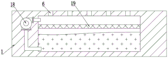
In the utility model, a rectangular groove is arranged in a workbench 1, dust absorption holes 6 are distributed at equal intervals on the top of the workbench 1, and the dust absorption holes 6 are communicated with the rectangular groove.
In the utility model, an air pump 18 is arranged in the workbench 1, the input end of the air pump 18 is communicated with the rectangular groove, and the air pump 18 adsorbs dust generated by polishing.
In the utility model, a partition plate 19 is fixedly connected inside the rectangular groove, the rectangular groove is divided into a negative pressure cavity and a water cavity by the partition plate 19, the negative pressure cavity is communicated with the input end of an air pump 18, the water cavity is communicated with the output end of the air pump 18, the output end of the air pump 18 is positioned at the bottom of the water cavity, the air pump 18 can enable the air cavity to generate negative pressure, a dust suction hole 6 generates suction force, dust generated by grinding is adsorbed, and the adsorbed dust can be input into the water cavity from the output end of the air pump 18 and is mixed with water for collection.
The working principle of the utility model is as follows:
a workpiece to be polished is placed on a fixing mechanism on a workbench 1, the prior art is adopted, then the angle between a polishing disc 11 and a surface to be polished is adjusted, under the action of a controller, four electric telescopic rods 9 can extend and shorten respectively, so that a fixed disc II 10 can rotate around a rotary ball II 15, the polishing disc 11 can be adjusted in multiple directions, a motor I7 can drive the polishing disc 11 to rotate and adjust in multiple directions, the motor II 16 drives a lead screw 17 to rotate, the lead screw 17 acts on a movable block 4, the movable block 4 moves left and right, the polishing disc 11 is adjusted left and right, the hydraulic rod 3 adjusts the height of the polishing disc 11, after adjustment is completed, polishing operation is started, the air pump 18 can enable negative pressure to be generated in an air cavity, suction force is generated in a dust suction hole 6, dust generated by polishing is adsorbed, and the adsorbed dust can be input into a water cavity from the output end of the air pump 18, mixing with water, and collecting.
Although the present invention has been described in detail with reference to the foregoing embodiments, it will be apparent to those skilled in the art that various changes in the embodiments and/or modifications of the utility model can be made, and equivalents and modifications of some features of the utility model can be made without departing from the spirit and scope of the utility model.
Claims (7)
1. The polishing device convenient for angle adjustment for the automobile parts comprises a workbench (1), wherein a moving mechanism is arranged at the top of the workbench (1), a hydraulic rod (3) is installed on the moving mechanism, and is characterized in that a first motor (7) is fixedly connected to one end of a piston rod of the hydraulic rod (3), a first fixed disk (8) is fixedly connected to one end of an output shaft of the first motor (7), a fixed rod (14) is fixedly connected to the middle of the outer wall of the bottom of the first fixed disk (8), a second rotating ball (15) is fixedly connected to one end of the fixed rod (14), a ball seat (13) which is distributed in a rectangular shape is fixedly connected to the outer wall of the bottom of the first fixed disk (8), a first rotating ball (12) is rotatably connected to the inside of the ball seat (13), an electric telescopic rod (9) is fixedly connected to the outer wall of the first rotating ball (12), and a second fixed disk (10) is hinged to one end of the piston rod of the electric telescopic rod (9), the fixed disc II (10) and the rotating ball II (15) form a running fit, the middle part of the outer wall of the bottom of the fixed disc II (10) is fixedly connected with a motor, and one end of an output shaft of the motor is fixedly connected with a polishing disc (11).
2. The automobile part polishing device convenient for angle adjustment according to claim 1, wherein the moving mechanism comprises a U-shaped frame (2) fixedly connected to the workbench (1), an installation groove is formed in the outer wall of the top of the U-shaped frame (2), the inner walls of two sides of the installation groove are commonly connected with a lead screw (17) through a bearing, a second motor (16) for driving the lead screw (17) to rotate is fixedly connected to the outer wall of one side of the U-shaped frame (2), a moving block (4) is connected to the outer wall of the lead screw (17) through a thread, and the moving block (4) is fixedly connected with the hydraulic rod (3).
3. The automobile part polishing device convenient for angle adjustment according to claim 2, wherein a sliding rail is arranged on an inner wall of the mounting groove, a sliding block is fixedly connected to an outer wall of the moving block (4), and the sliding rail and the sliding block form a sliding fit.
4. The automobile part grinding device convenient for angle adjustment according to claim 1, wherein a dust guard (5) is fixedly connected to the outer wall of the top of the workbench (1), and the dust guard (5) is U-shaped.
5. The automobile part grinding device convenient for angle adjustment according to claim 1, wherein a rectangular groove is formed in the workbench (1), dust suction holes (6) are formed in the top of the workbench (1) and are distributed equidistantly, and the dust suction holes (6) are communicated with the rectangular groove.
6. The automobile part polishing device convenient for angle adjustment according to claim 1, wherein an air pump (18) is installed inside the workbench (1), and an input end of the air pump (18) is communicated with the rectangular groove.
7. The automobile part polishing device convenient for angle adjustment according to claim 5, wherein a partition plate (19) is fixedly connected inside the rectangular groove, the partition plate (19) divides the rectangular groove into a negative pressure cavity and a water cavity which are distributed up and down, the negative pressure cavity is communicated with an input end of the air pump (18), the water cavity is communicated with an output end of the air pump (18), and an output end of the air pump (18) is located at the bottom of the water cavity.
Priority Applications (1)
| Application Number | Priority Date | Filing Date | Title |
|---|---|---|---|
| CN202121946892.6U CN216138691U (en) | 2021-08-19 | 2021-08-19 | Automobile parts grinding device convenient to angle regulation |
Applications Claiming Priority (1)
| Application Number | Priority Date | Filing Date | Title |
|---|---|---|---|
| CN202121946892.6U CN216138691U (en) | 2021-08-19 | 2021-08-19 | Automobile parts grinding device convenient to angle regulation |
Publications (1)
| Publication Number | Publication Date |
|---|---|
| CN216138691U true CN216138691U (en) | 2022-03-29 |
Family
ID=80806709
Family Applications (1)
| Application Number | Title | Priority Date | Filing Date |
|---|---|---|---|
| CN202121946892.6U Active CN216138691U (en) | 2021-08-19 | 2021-08-19 | Automobile parts grinding device convenient to angle regulation |
Country Status (1)
| Country | Link |
|---|---|
| CN (1) | CN216138691U (en) |
-
2021
- 2021-08-19 CN CN202121946892.6U patent/CN216138691U/en active Active
Similar Documents
| Publication | Publication Date | Title |
|---|---|---|
| CN205465519U (en) | A five -axis machine tool for burnishing and polishing wire drawing | |
| CN201419352Y (en) | Automatic polishing device for polishing handle | |
| CN105729246A (en) | Multifunctional five-axis machine tool | |
| CN209304296U (en) | A kind of five-shaft numerical control sander | |
| CN110842579A (en) | Integrated device for polishing and cutting surface of metal plate | |
| CN216138691U (en) | Automobile parts grinding device convenient to angle regulation | |
| CN109290904A (en) | A kind of station anticollision damping rubber processing unit (plant) | |
| CN116586985A (en) | Cutting device is used in bearing frame processing | |
| CN217571837U (en) | Five-axis machining device | |
| CN116442100A (en) | Solid wood strip polishing machine | |
| CN207930668U (en) | Double-stroke feeding robot | |
| CN114536013B (en) | Multifunctional numerical control machine tool | |
| CN205520751U (en) | Multi -functional five -axis machine tool | |
| CN113829225A (en) | Hydraulic press rivet burnishing device | |
| CN113977423A (en) | Numerical control vertical double-grinding head multifunctional grinding machine | |
| CN113878484A (en) | Burnishing machine with grinding function for metal production | |
| CN112548748A (en) | Edge grinding machine and edge grinding method for display screen glass | |
| CN220051262U (en) | Polishing mechanism | |
| CN218518191U (en) | Vertical machining center machine for mechanical parts | |
| CN219836691U (en) | Hardware processing paint spraying equipment | |
| CN220806779U (en) | Mechanical accessory polishing device | |
| CN215394406U (en) | Energy-concerving and environment-protective type brake drum apparatus for producing | |
| CN212419665U (en) | Electric spindle lathe for turning super-bright surface and mirror surface of hub | |
| CN219094769U (en) | Grinding machine for hardware machining | |
| CN219053919U (en) | Mechanical part machining clamping table |
Legal Events
| Date | Code | Title | Description |
|---|---|---|---|
| GR01 | Patent grant | ||
| GR01 | Patent grant |