CN216116256U - Reservoir water level water-holding capacity measuring device - Google Patents
Reservoir water level water-holding capacity measuring device Download PDFInfo
- Publication number
- CN216116256U CN216116256U CN202120991964.2U CN202120991964U CN216116256U CN 216116256 U CN216116256 U CN 216116256U CN 202120991964 U CN202120991964 U CN 202120991964U CN 216116256 U CN216116256 U CN 216116256U
- Authority
- CN
- China
- Prior art keywords
- fixedly connected
- water level
- rod
- hollow
- measuring
- Prior art date
- Legal status (The legal status is an assumption and is not a legal conclusion. Google has not performed a legal analysis and makes no representation as to the accuracy of the status listed.)
- Active
Links
Images


Abstract
The utility model discloses a reservoir water level capacity of holding measuring device includes first supporting disk and the L type base that the level was placed, the second supporting disk that first supporting disk one side fixedly connected with level was placed, and second supporting disk top is equipped with the observation subassembly, the vertical inserted bar of placing of L type base long limit bottom end fixedly connected with a plurality of, and be the rectangular array distribution between the inserted bar, the vertical hollow rod of placing of L type base long limit top fixedly connected with, and be equipped with flexible subassembly in the hollow rod, hollow rod outer wall cover is equipped with the hollow strip that the level was placed, and the hollow strip bottom is equipped with the water level measurement subassembly. According to the utility model, the plurality of inserted rods are arranged, so that water surface shaking is avoided, the measurement stability is ensured, the measurement accuracy is improved, the floating object removing assembly is matched, the determination error caused by the floating object is avoided, and the accuracy of the measurement result is further improved.
Description
Technical Field
The utility model relates to the technical field of water level measurement, in particular to a device for measuring the water level and water holding capacity of a reservoir.
Background
The water level refers to the elevation of the free water surface relative to a certain base plane, the distance between the water surface and the river bottom is called water depth, the base plane used for calculating the water level can be an absolute base plane which is used by taking the elevation of a certain characteristic sea level as a zero-point leveling base plane, and the absolute base plane is a common yellow sea level; the elevation of a specific point can also be used as a zero point for calculating the water level by reference, the reference point is called a base plane of a measuring station, the water level is the most intuitive factor for reflecting the water condition of the water body, the change of the water level is mainly caused by the increase and decrease of the water quantity of the water body, a water level process line is a curve of the water level at a certain position along with the change of time, the horizontal coordinate is time, and the vertical coordinate is the water level.
In order to facilitate observation of the water level in hydraulic engineering management, a measuring device is required.
The existing measuring device is complex in structure, inconvenient to operate and high in cost, cannot guarantee the stability of the measuring process, can cause inaccurate measuring results, cannot measure according to the depth of a water body, reduces the practicability of the device, facilitates offshore detection, and grasps the height of the water level in real time, and the reservoir water level water holding capacity measuring device is provided.
SUMMERY OF THE UTILITY MODEL
The utility model aims to solve the defects in the prior art and provides a device for measuring the water level capacity of a reservoir.
In order to achieve the purpose, the utility model adopts the following technical scheme:
a device for measuring water level capacity of a reservoir comprises a first supporting disc and an L-shaped base, wherein one side of the first supporting disc is fixedly connected with a second supporting disc, the second supporting disc is horizontally arranged, an observation assembly is arranged at the top end of the second supporting disc, a plurality of insertion rods, which are vertically arranged, are fixedly connected with the bottom end of the long side of the L-shaped base, the insertion rods are distributed in a rectangular array manner, a hollow rod, which is vertically arranged, is fixedly connected with the top end of the long side of the L-shaped base, a telescopic assembly is arranged in the hollow rod, a horizontally arranged hollow strip is sleeved on the outer wall of the hollow rod, a water level measuring assembly is arranged at the bottom end of the hollow strip, a group of driving assemblies and two groups of floater removing assemblies are arranged in the hollow strip, the driving assemblies are in transmission fit with the floater removing assemblies, a buoyancy ball is horizontally arranged and fixedly connected with one side, far away from the hollow rod, of the first supporting disc is fixedly connected with an electric telescopic rod, which is vertically arranged, which is close to one side of the second supporting disc, and the telescopic end of the electric telescopic rod is fixedly connected with the top end of the L-shaped base.
Furthermore, the opposite side of the top end of the second supporting disk is provided with mounting holes, and the bottom end of the second supporting disk is fixedly connected with a plurality of anti-skid lugs distributed in a rectangular array at positions close to the two mounting holes.
Further, the observation subassembly includes vertical control and the support column of placing, hollow rod one side fixed connection is kept away from with L type base minor face in the control, support column bottom and second supporting disk top middle part fixed connection, and the display screen that support column top fixedly connected with slope was placed.
Further, drive assembly includes the biax motor that the level was placed and the support of vertical placing, support top and biax motor bottom fixed connection, and support bottom and hollow strip inner wall bottom middle part fixed connection, subassembly fixed connection is all clear away with the floater to two output shafts of biax motor.
Furthermore, the floater removing assembly comprises a horizontally arranged worm, a worm wheel and a vertically arranged C-shaped rod, one end of the worm is rotatably connected with one side, away from the double-shaft motor, of the inner wall of the hollow strip, the other end of the worm is fixedly connected with an output shaft of the double-shaft motor, the worm is meshed with the worm wheel, the opposite end of the C-shaped rod penetrates through the hollow strip and is fixedly connected with the inner wall of the worm wheel, the position, away from the worm wheel, of the opposite end of the C-shaped rod is sleeved with a horizontally arranged sealing rubber ring, the sealing rubber ring is fixedly connected with the inner wall of the hollow strip, one side, close to the hollow strip, of the C-shaped rod is sleeved with a horizontally arranged porous push plate, and the porous push plate and the C-shaped rod are fixed through bolts.
Further, flexible subassembly includes vertical T type many arriss poles and the spring of placing, the spring bottom welds with hollow rod inner wall bottom, and the welding of spring top and T type many arriss pole bottom, hollow rod and first support plate bottom fixed connection are passed on T type many arriss pole top.
Furthermore, the water level measuring assembly comprises a horizontally arranged rotating rod, one end, opposite to the rotating rod, of the rotating rod is respectively connected with the short edge of the L-shaped base and the outer wall of the hollow rod in a rotating mode, a vertically arranged measuring tape is wound on the surface of the rotating rod, and the top end of the measuring tape is fixedly connected with the bottom end of the outer wall of the hollow rod.
Further, the water level measuring assembly comprises a radar water level gauge which is horizontally placed, and the radar water level gauge is fixedly connected with the bottom end of the outer wall of the hollow strip.
Further, control and radar fluviograph all are connected with the display screen electricity, the display screen is connected with electric telescopic handle electricity, and the display screen even has the controller, double-shaft motor all link there is the switch, and the switch even has the power cord.
The utility model has the beneficial effects that:
1. through setting up a plurality of inserted bar, avoid the surface of water to rock, guarantee measuring stability, improve measuring accuracy, the subassembly is clear away to the floater that the cooperation set up, avoids the floater to cause the survey error, has further improved measuring result's accuracy, combines the drive assembly who sets up for clear away speed has improved work efficiency.
2. Through setting up second supporting disk and mounting hole, easy to assemble, portable cooperates the skid proof block who sets up, has improved measuring stability, and the offshore observation of being convenient for combines camera and the display screen that sets up, can real-time detection water level, and more audio-visual record data makes things convenient for the operator to use.
3. Through setting up flexible subassembly, satisfy the survey of different degree of depth reservoir water levels, improve the application scope of device, the water level measurement subassembly that the cooperation set up can the short-term test height of water level, and the measuring tool's of also being convenient for maintenance and change combine the buoyancy ball that sets up, alleviate the measurement degree of difficulty, ensure measuring result.
Drawings
Fig. 1 is a schematic perspective view of a reservoir water level water holding amount measuring device according to the present invention, including an embodiment 1;
FIG. 2 is a schematic view of a portion of a telescopic assembly of a reservoir water level capacity measuring device according to the present invention;
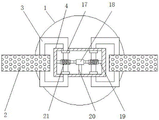
fig. 3 is a schematic plan sectional view of a reservoir water level holding capacity measuring apparatus according to embodiment 1 of the present invention;
FIG. 4 is a schematic diagram of an internal side view of a hollow bar of a reservoir water level capacity measuring device according to the present invention;
FIG. 5 is a schematic view of an internal top view of a hollow bar of a reservoir water level capacity measuring device according to the present invention;
fig. 6 is a schematic plan sectional view of a reservoir water level holding capacity measuring apparatus according to embodiment 2 of the present invention.
In the figure: 1. a buoyant ball; 2. a porous push plate; 3. a C-shaped rod; 4. a hollow bar; 5. measuring a tape measure; 6. a T-shaped polygonal rod; 7. a first support tray; 8. an electric telescopic rod; 9. an anti-slip bump; 10. a second support disc; 11. an L-shaped base; 12. a spring; 13. inserting a rod; 14. a hollow shaft; 15. a rotating rod; 16. monitoring; 17. sealing the rubber ring; 18. a double-shaft motor; 19. a worm; 20. a support; 21. a worm gear; 22. a radar level gauge; 23. a support pillar; 24. a display screen.
Detailed Description
The technical solutions in the embodiments of the present invention will be clearly and completely described below with reference to the drawings in the embodiments of the present invention, and it is obvious that the described embodiments are only a part of the embodiments of the present invention, and not all of the embodiments.
Example 1
Referring to fig. 1-5, a device for measuring water level capacity of a reservoir comprises a first support disc 7 and an L-shaped base 11 which are horizontally arranged, one side of the first support disc 7 is fixedly connected with a second support disc 10 which is horizontally arranged through bolts, the top end of the second support disc 10 is provided with an observation assembly, the bottom end of the long side of the L-shaped base 11 is fixedly connected with a plurality of inserted rods 13 which are vertically arranged through bolts, the inserted rods 13 are distributed in a rectangular array, the top end of the long side of the L-shaped base 11 is fixedly connected with a hollow rod 14 which is vertically arranged through bolts, a telescopic assembly is arranged in the hollow rod 14, the outer wall of the hollow rod 14 is sleeved with a horizontally arranged hollow strip 4, the bottom end of the hollow strip 4 is provided with a water level measuring assembly, a group of driving assemblies and two groups of floater removing assemblies are arranged in the hollow strip 4, the driving assemblies are in transmission fit with the floater removing assemblies, one side of the hollow strip 4 far away from the hollow rod 14 is fixedly connected with a horizontally arranged buoyancy ball 1 through bolts, the bottom end of the first supporting disk 7 is fixedly connected with a vertically placed electric telescopic rod 8 through a bolt at one side close to the second supporting disk 10, the telescopic end of the electric telescopic rod 8 is fixedly connected with the top end of the L-shaped base 11 through a bolt, mounting holes are formed at one side opposite to the top end of the second supporting disk 10, a plurality of anti-skid blocks 9 distributed in a rectangular array are fixedly connected with the bottom end of the second supporting disk 10 through bolts at positions close to the two mounting holes, the observation assembly comprises a vertically placed monitor 16 and a supporting column 23, the monitor 16 is fixedly connected with one side, away from the hollow rod 14, of the short edge of the L-shaped base 11 through a bolt, the bottom end of the supporting column 23 is fixedly connected with the middle part of the top end of the second supporting disk 10 through a bolt, the top end of the supporting column 23 is fixedly connected with a display screen 24 obliquely placed through a bolt, the installation is convenient and the carrying is convenient, and the anti-skid blocks are arranged in a matching way, the stability of measurement is improved, offshore observation is facilitated, a camera and a display screen are combined, the water level can be detected in real time, data can be recorded more visually, and the device is convenient for an operator to use, the driving assembly comprises a horizontally placed double-shaft motor 18 and a vertically placed support 20, the top end of the support 20 is fixedly connected with the bottom end of the double-shaft motor 18 through a bolt, the bottom end of the support 20 is fixedly connected with the middle part of the bottom end of the inner wall of the hollow strip 4 through a bolt, two output shafts of the double-shaft motor 18 are fixedly connected with the floater removing assembly through bolts, the floater removing assembly comprises a horizontally placed worm 19, a worm wheel 21 and a vertically placed C-shaped rod 3, one end of the worm 19 is rotatably connected with one side, far away from the double-shaft motor 18, of the inner wall of the hollow strip 4, the other end of the worm 19 is fixedly connected with the output shaft of the double-shaft motor 18 through a bolt, the worm 19 is meshed with the worm wheel 21, the opposite end of the C-shaped rod 3 penetrates through the hollow strip 4 and the inner wall of the worm wheel 21 through a bolt, the position, far away from the worm wheel 21, of the opposite end of the C-shaped rod 3 is sleeved with a horizontally placed sealing rubber ring 17, the two sealing rubber rings 17 are fixedly connected with the inner wall of the hollow strip 4 through bolts, one side, close to the hollow strip 4, of the C-shaped rod 3 is sleeved with a horizontally placed porous push plate 2, the porous push plate 2 and the C-shaped rod 3 are fixed through bolts, water surface shaking is avoided by arranging a plurality of inserting rods, the stability of measurement is ensured, the accuracy of measurement is improved, a floater removing assembly is arranged in a matched mode, the determination error caused by floaters is avoided, the accuracy of a measurement result is further improved, the removing speed is accelerated by combining with a driving assembly arranged, the working efficiency is improved, the telescopic assembly comprises a T-shaped multi-edge rod 6 and a spring 12 which are vertically arranged, the bottom end of the spring 12 is welded with the bottom end of the inner wall of the hollow rod 14, and the top end of the spring 12 is welded with the bottom end of the T-shaped multi-edge rod 6, the top end of a T-shaped multi-edge rod 6 penetrates through a hollow rod 14 to be fixedly connected with the bottom end of a first supporting disc 7 through bolts, a water level measuring assembly comprises a horizontally placed rotating rod 15, one opposite end of the rotating rod 15 is respectively connected with the short edge of an L-shaped base 11 and the outer wall of the hollow rod 14 in a rotating mode, a vertically placed measuring tape 5 is wound on the surface of the rotating rod 15, the top end of the measuring tape 5 is fixedly connected with the bottom end of the outer wall of a hollow strip 4 through bolts, the measuring device meets the measurement of the water level of reservoirs with different depths by arranging a telescopic assembly, the application range of the device is improved, the height of the water level can be rapidly detected by matching the arranged water level measuring assembly, the maintenance and replacement of a measuring tool are convenient, the arranged buoyancy ball is combined, the measuring difficulty is reduced, the measuring result is ensured, a monitoring device 16 and a radar level gauge 22 are both electrically connected with a display screen 24, the display screen 24 is electrically connected with an electric telescopic rod 8, and the display screen 24 is connected with a controller, controller, biax motor 18 all link has the switch, and the switch even has the power cord.
The working principle of the embodiment is as follows: firstly, the device is put into a reservoir to be measured, bolts are screwed into mounting holes to fix a second supporting plate 10 with the ground on the bank side, the stability of measurement is improved, then an electric telescopic rod 8 is switched on, an L-shaped base 11 is driven to move downwards by controlling the extension work of the electric telescopic rod, an inserting rod 13 is driven to be fixed with the bottom of the reservoir, the fixing condition of the inserting rod 13 is observed in a display screen 24 by arranging a camera 16, information is fed back to the electric telescopic rod 8, the electric telescopic rod 8 is closed, the automatic operation is realized, the working strength is lightened, the working efficiency is improved, the accuracy of a measurement result is ensured, meanwhile, the water level measurement can be carried out on different depths by arranging a spring 12 and a T-shaped multi-rod edge 7, the measuring tape 5 wound on a rotating rod 15 is pulled to rotate under the action of a buoyancy ball 1, the height of the reservoir can be more intuitively detected, satisfy different survey demands to switch on the power of biax motor 18, under the meshing effect of worm 19 and worm wheel 21, through the positive and negative rotation of biax motor 18, drive C type pole 3 and rotate, also driven porous push pedal 2 along the horizontal swing of surface of water, isolated the floater near measuring tape 5, further improved measuring result's accuracy.
Example 2
Refer to fig. 2, 4, 5, 6, a reservoir water level holds water content measuring device this embodiment is for embodiment 1, the main difference lies in this embodiment, water level measurement subassembly includes radar fluviograph 22 that the level was placed, and bolt fixed connection is passed through with 4 outer wall bottoms of hollow strip to radar fluviograph 22, the water level measurement subassembly that the cooperation set up, can the short-term test height of water level, the measuring tool's of also being convenient for maintenance and change, radar fluviograph 22 is connected with 24 electricity on the display screen, display screen 24 is connected with 8 electricity on electric telescopic handle, and display screen 24 even has the controller, the controller even has the switch, and the switch even has the power cord.
The working principle of the embodiment is as follows: firstly, the device is put into a reservoir to be measured, bolts are screwed into mounting holes to fix a second supporting plate 10 with the ground on the bank side, the stability of measurement is improved, then an electric telescopic rod 8 is switched on, an L-shaped base 11 is driven to move downwards by controlling the extension work of the electric telescopic rod, an inserting rod 13 is driven to be fixed with the bottom of the reservoir, the fixing condition of the inserting rod 13 is observed in a display screen 24 by arranging a camera 16, information is fed back to the electric telescopic rod 8, the electric telescopic rod 8 is closed, the automatic operation is realized, the working strength is reduced, the working efficiency is improved, the accuracy of the measurement result is ensured, meanwhile, the water level measurement can be carried out on reservoirs with different depths by arranging a spring 12 and a T-shaped multi-edge rod 7, a buoyancy ball 1 is driven to rise to the water surface, a radar water level gauge 22 is used for detecting the height of the reservoir, so as to meet different measurement requirements, and the power supply of the double-shaft motor 18 is switched on, under the meshing action of the worm 19 and the worm wheel 21, the C-shaped rod 3 is driven to rotate through the positive and negative rotation of the double-shaft motor 18, the porous push plate 2 is also driven to horizontally swing along the water surface, the floating objects near the measuring tape 5 are isolated, and the accuracy of the measuring result is further improved.
In the description of the present invention, it is to be understood that the terms "coaxial", "bottom", "one end", "top", "middle", "other end", "upper", "one side", "top", "inner", "front", "center", "both ends", "first", "second", etc., indicate orientations or positional relationships based on those shown in the drawings, and are only for convenience of description and simplicity of description, and do not indicate or imply that the device or element being referred to must have a particular orientation, be constructed and operated in a particular orientation, and thus, are not to be construed as limiting the present invention.
In the description of the present patent application, it is to be noted that unless otherwise explicitly stated or limited, the terms "mounted," "connected," and "disposed" are to be interpreted broadly, and may be, for example, fixedly connected, disposed, detachably connected, disposed, or integrally connected and disposed, and the specific meaning of the terms in the patent will be understood by those skilled in the art according to the specific situation.
The above description is only for the preferred embodiment of the present invention, but the scope of the present invention is not limited thereto, and any person skilled in the art should be considered to be within the technical scope of the present invention, and equivalent alternatives or modifications according to the technical solution of the present invention and the inventive concept thereof should be covered by the scope of the present invention.
Claims (9)
1. A reservoir water level water holding capacity measuring device comprises a first supporting disc (7) and an L-shaped base (11) which are horizontally arranged, and is characterized in that one side of the first supporting disc (7) is fixedly connected with a second supporting disc (10) which is horizontally arranged, an observation assembly is arranged at the top end of the second supporting disc (10), a plurality of vertically-arranged inserted rods (13) are fixedly connected to the bottom ends of the long edges of the L-shaped base (11), the inserted rods (13) are distributed in a rectangular array mode, a vertically-arranged hollow rod (14) is fixedly connected to the top ends of the long edges of the L-shaped base (11), a telescopic assembly is arranged in the hollow rod (14), a horizontally-arranged hollow strip (4) is sleeved on the outer wall of the hollow rod (14), a water level measuring assembly is arranged at the bottom end of the hollow strip (4), a set of driving assemblies and two sets of floating object clearing assemblies are arranged in the hollow strip (4), and drive assembly all clears away the subassembly with the floater and forms the transmission cooperation, hollow bar (4) are kept away from hollow pole (14) one side fixedly connected with level and are placed buoyancy ball (1), first supporting disk (7) bottom is close to vertical electric telescopic handle (8) of placing of second supporting disk (10) one side fixedly connected with, and electric telescopic handle (8) flexible end and L type base (11) top fixed connection.
2. The device for measuring the water level capacity of the reservoir according to claim 1, wherein the opposite side of the top end of the second supporting plate (10) is provided with mounting holes, and a plurality of anti-skid lugs (9) distributed in a rectangular array are fixedly connected to the bottom end of the second supporting plate (10) near the two mounting holes.
3. The device for measuring the water level capacity of the reservoir according to claim 2, wherein the observation assembly comprises a vertically placed monitor (16) and a support column (23), the monitor (16) is fixedly connected with one side of the short side of the L-shaped base (11) far away from the hollow rod (14), the bottom end of the support column (23) is fixedly connected with the middle part of the top end of the second support plate (10), and the top end of the support column (23) is fixedly connected with an obliquely placed display screen (24).
4. The device for measuring the water level capacity of the reservoir according to claim 3, wherein the driving assembly comprises a horizontally placed double-shaft motor (18) and a vertically placed bracket (20), the top end of the bracket (20) is fixedly connected with the bottom end of the double-shaft motor (18), the bottom end of the bracket (20) is fixedly connected with the middle part of the bottom end of the inner wall of the hollow bar (4), and two output shafts of the double-shaft motor (18) are fixedly connected with the floating object removing assembly.
5. The device for measuring the water level and the water holding capacity of the reservoir according to claim 4, wherein the floater removing component comprises a horizontally arranged worm (19), a horizontally arranged worm wheel (21) and a vertically arranged C-shaped rod (3), one end of the worm (19) is rotatably connected with one side, away from the double-shaft motor (18), of the inner wall of the hollow strip (4), the other end of the worm (19) is fixedly connected with an output shaft of the double-shaft motor (18), the worm (19) is meshed with the worm wheel (21), the opposite end of the C-shaped rod (3) penetrates through the hollow strip (4) and is fixedly connected with the inner wall of the worm wheel (21), a horizontally arranged sealing rubber ring (17) is sleeved at the position, away from the worm wheel (21), of the opposite end of the C-shaped rod (3), the two sealing rubber rings (17) are fixedly connected with the inner wall of the hollow strip (4), a horizontally arranged porous push plate (2) is sleeved on one side, close to the hollow strip (4), of the C-shaped rod (3), and the porous push plate (2) and the C-shaped rod (3) are fixed through bolts.
6. The device for measuring the water level capacity of the reservoir according to claim 5, wherein the telescopic assembly comprises a T-shaped multi-edge rod (6) and a spring (12) which are vertically placed, the bottom end of the spring (12) is welded with the bottom end of the inner wall of the hollow rod (14), the top end of the spring (12) is welded with the bottom end of the T-shaped multi-edge rod (6), and the top end of the T-shaped multi-edge rod (6) penetrates through the hollow rod (14) to be fixedly connected with the bottom end of the first supporting disc (7).
7. The reservoir water level capacity measuring device as claimed in claim 6, wherein the water level measuring assembly comprises a horizontally placed rotating rod (15), one end of the rotating rod (15) is rotatably connected with the short side of the L-shaped base (11) and the outer wall of the hollow rod (14), the vertically placed measuring tape (5) is wound on the surface of the rotating rod (15), and the top end of the measuring tape (5) is fixedly connected with the bottom end of the outer wall of the hollow strip (4).
8. The reservoir water level capacity measuring device according to claim 6, wherein the water level measuring assembly comprises a radar water level gauge (22) which is horizontally placed, and the radar water level gauge (22) is fixedly connected with the bottom end of the outer wall of the hollow bar (4).
9. The reservoir water level capacity measuring device according to claim 7 or 8, wherein the monitor (16) and the radar level gauge (22) are electrically connected with a display screen (24), the display screen (24) is electrically connected with the electric telescopic rod (8), the display screen (24) is connected with a controller, the controller and the double-shaft motor (18) are connected with a switch, and the switch is connected with a power line.
Priority Applications (1)
| Application Number | Priority Date | Filing Date | Title |
|---|---|---|---|
| CN202120991964.2U CN216116256U (en) | 2021-05-11 | 2021-05-11 | Reservoir water level water-holding capacity measuring device |
Applications Claiming Priority (1)
| Application Number | Priority Date | Filing Date | Title |
|---|---|---|---|
| CN202120991964.2U CN216116256U (en) | 2021-05-11 | 2021-05-11 | Reservoir water level water-holding capacity measuring device |
Publications (1)
| Publication Number | Publication Date |
|---|---|
| CN216116256U true CN216116256U (en) | 2022-03-22 |
Family
ID=80687271
Family Applications (1)
| Application Number | Title | Priority Date | Filing Date |
|---|---|---|---|
| CN202120991964.2U Active CN216116256U (en) | 2021-05-11 | 2021-05-11 | Reservoir water level water-holding capacity measuring device |
Country Status (1)
| Country | Link |
|---|---|
| CN (1) | CN216116256U (en) |
Cited By (1)
| Publication number | Priority date | Publication date | Assignee | Title |
|---|---|---|---|---|
| CN115326488A (en) * | 2022-10-14 | 2022-11-11 | 山东省地质矿产勘查开发局八〇一水文地质工程地质大队(山东省地矿工程勘察院) | Intelligent surveying equipment for hydrogeology investigation |
-
2021
- 2021-05-11 CN CN202120991964.2U patent/CN216116256U/en active Active
Cited By (2)
| Publication number | Priority date | Publication date | Assignee | Title |
|---|---|---|---|---|
| CN115326488A (en) * | 2022-10-14 | 2022-11-11 | 山东省地质矿产勘查开发局八〇一水文地质工程地质大队(山东省地矿工程勘察院) | Intelligent surveying equipment for hydrogeology investigation |
| CN115326488B (en) * | 2022-10-14 | 2023-01-24 | 山东省地质矿产勘查开发局八〇一水文地质工程地质大队(山东省地矿工程勘察院) | Intelligent surveying equipment for hydrogeology investigation |
Similar Documents
| Publication | Publication Date | Title |
|---|---|---|
| CN111806632B (en) | Measuring ship for underwater topography mapping | |
| CN216116256U (en) | Reservoir water level water-holding capacity measuring device | |
| CN214306162U (en) | Adjustable foundation pit monitoring device | |
| CN111521217A (en) | Data acquisition device for hydrology and water resource investigation and evaluation | |
| CN213956528U (en) | Suspension reservoir water level measuring equipment | |
| CN210135978U (en) | Safety monitoring system based on Beidou navigation satellite | |
| CN209727919U (en) | A kind of adjustable water monitoring device of measurement water level depth | |
| CN210513332U (en) | Underground water level monitoring device | |
| CN216559233U (en) | Water level monitoring device for hydraulic engineering | |
| CN110901845B (en) | Accurate reading instrument of boats and ships water gauge under water | |
| CN213180230U (en) | Intelligent information monitoring device that flood prevention was used | |
| CN211904323U (en) | Earth and stone underground water level measuring device | |
| CN212513202U (en) | Hydrogeology drilling water level automatic acquisition ware | |
| CN213180757U (en) | Hand-held type soil sampling device | |
| CN215178843U (en) | Ocean water quality testing sampling equipment | |
| CN112834716A (en) | Hydrology water resource monitoring devices | |
| CN206073975U (en) | A kind of level measurement device for column foot | |
| CN219161396U (en) | Water regime early warning device | |
| CN212320853U (en) | River surface water level monitoring equipment for boulder construction area | |
| CN215573254U (en) | Water level monitoring device for hydraulic engineering | |
| CN218916331U (en) | Mapping device for water engineering mapping | |
| CN220819075U (en) | Hydraulic engineering measuring device | |
| CN212363366U (en) | Sewage pool water level detection device for sewage treatment | |
| CN213932721U (en) | Measuring device for hydraulic engineering convenient to observe water level | |
| CN217384404U (en) | Water level measuring device for reservoir |
Legal Events
| Date | Code | Title | Description |
|---|---|---|---|
| GR01 | Patent grant | ||
| GR01 | Patent grant |