CN216062351U - Filtering device for fish pond for removing solid suspended matters - Google Patents
Filtering device for fish pond for removing solid suspended matters Download PDFInfo
- Publication number
- CN216062351U CN216062351U CN202122678020.2U CN202122678020U CN216062351U CN 216062351 U CN216062351 U CN 216062351U CN 202122678020 U CN202122678020 U CN 202122678020U CN 216062351 U CN216062351 U CN 216062351U
- Authority
- CN
- China
- Prior art keywords
- filtering
- cavity
- pipe
- water suction
- tank
- Prior art date
- Legal status (The legal status is an assumption and is not a legal conclusion. Google has not performed a legal analysis and makes no representation as to the accuracy of the status listed.)
- Active
Links
Images


Landscapes
- Farming Of Fish And Shellfish (AREA)
Abstract
The utility model relates to the technical field of filtering devices, in particular to a filtering device for a fish pond for removing solid suspended matters, which saves cost, improves filtering effect and improves practicability and comprises a filtering tank and a first filtering plate, wherein the filtering tank is internally provided with a cavity, the first filtering plate is obliquely arranged in the upper half area of the cavity, the cavity is divided into an upper cavity and a lower cavity, a first water suction pump is installed at the left end of the filtering tank, the output end of the first water suction pump is connected with a water suction pipe, a filtering basket is installed at the tail end of the water suction pipe, the output end of the water suction pump extends into the upper cavity from the left end of the filtering tank, a sand filtering device is transversely installed in the lower half area of the lower cavity, a second water suction pump is installed on the bottom wall of the lower cavity, a V-shaped water collecting cover is installed below the first filtering plate, a sewer pipe is installed at the bottom end of the water collecting cover, and the output end of the sewer pipe penetrates through the middle of the sand filtering device and is connected with the input end of the second water suction pump.
Description
Technical Field
The utility model relates to the technical field of filtering devices, in particular to a filtering device for a fish pond for removing solid suspended matters.
Background
As is well known, in the process of fish culture, as fish needs to be defecated, a large amount of suspended matters exist in a fish pond, the fish pond needs to be cleaned regularly in order to provide a good production environment for the fish, and the suspended solid matters in water are cleaned through a filtering device, so that the fish culture device is widely used in the field of fish culture; the current filter equipment for fish pond of getting rid of suspended solid uses the mode of adding the coagulant or salvaging to clear up, discovers in the use that current mode can increase the cost, waste time and energy, and the filter effect is relatively poor. Therefore, a filtering device for a fish pond for removing solid suspended substances is provided.
SUMMERY OF THE UTILITY MODEL
Technical problem to be solved
Aiming at the defects of the prior art, the filtering device for the fish pond for removing the solid suspended matters, provided by the utility model, has the advantages that the cost is saved, the filtering effect is improved, and the practicability is improved.
(II) technical scheme
In order to achieve the purpose, the utility model provides the following technical scheme: the utility model provides a get rid of solid suspended solid's filter equipment for fish pond, is including filtering jar and first filter, it has seted up the cavity to filter the jar, first filter slope is installed in the first half region of cavity to divide into cavity and lower cavity to the cavity, filter the left end of jar and install first suction pump, the output of first suction pump is connected with the drinking-water pipe, the filter basket is installed to the end of drinking-water pipe, and the output of first suction pump stretches into supreme cavity from the left end of filtering the jar, filter sand device is transversely installed to the second half region of cavity down, the second suction pump is installed to the diapire of cavity down, the water collecting cover of V type is installed to the below of first filter, the downcomer is installed to the bottom of water collecting cover, the output of downcomer runs through and is connected with the input of second suction pump from the middle part of filter sand device, filter the right-hand member of jar from last to installing the flushing pipe down in proper order, A drain pipe and a sewage discharge pipe.
Preferably, the filtering basket is welded by a steel wire mesh to form a cube, the top of each of the four sides of the filtering basket is provided with a flow inlet, and the bottom of the inner wall of the filtering basket is provided with a bottom plate.
Preferably, the sand filtering device comprises a storage box, a storage cavity is formed in the storage box, communicating ports are formed in the top end and the bottom end of the storage box, a sealing screen plate is installed in each communicating port, and the storage cavity is filled with filter sand.
Preferably, the left end and the right end of the filter tank are respectively provided with a driving motor through a rack, the output ends of the two groups of driving motors are respectively connected with a transmission shaft, the two groups of transmission shafts respectively penetrate through the middle parts of the left end and the right end of the storage tank and are respectively positioned on two sides of the sewer pipe, and the outer ends of the two groups of transmission shafts are uniformly provided with stirring rods.
Preferably, the drain pipe is positioned at the upper side of the storage tank and is contacted with the top end of the storage tank, and the outer ends of the flushing pipe, the drain pipe and the sewage discharge pipe are all provided with control valves.
Preferably, the first filter plate is high at the bottom of the right side, and the clearance mouth has been seted up to the upper half region of right-hand member of filter tank, install sealing door in the clearance mouth.
(III) advantageous effects
Compared with the prior art, the utility model provides a filtering device for a fish pond for removing solid suspended matters, which has the following beneficial effects: this get rid of solid suspended solid's filter equipment for fish pond, filter the float impurity of basket to the aquatic through drinking-water pipe end-to-end connection, the effect of collection has been played impurity through filtering the basket simultaneously, the slope is provided with first filter in the filter tank, the sand filtering device is transversely installed in the first region of lower chamber, setting through first filter and sand filtering device, carry out stage filtration to water in proper order, the drain pipe is installed to the right-hand member of filtering the jar, water after the filtration overflows through the drain pipe, thereby accomplish sewage filtration, the filter effect is improved, and the practicality is improved.
Drawings
FIG. 1 is a schematic cross-sectional view of the present invention;
FIG. 2 is a schematic top sectional view of the sand screen of the present invention;
fig. 3 is a schematic cross-sectional view of a filter basket according to the present invention.
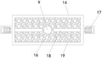
In the drawings, the reference numbers: 1. a filter tank; 2. a first water pump; 3. a water pumping pipe; 4. a filter basket; 5. a sand filtering device; 6. a second water pump; 7. a first filter plate; 8. a water collection cover; 9. a sewer pipe; 10. a flush tube; 11. a drain pipe; 12. a blow-off pipe; 13. a base plate; 14. a storage box; 15. sealing the mesh plate; 16. filtering sand; 17. a drive motor; 18. a drive shaft; 19. a stirring rod; 20. a control valve; 21. and (4) sealing the door.
Detailed Description
The technical solutions in the embodiments of the present invention will be clearly and completely described below with reference to the drawings in the embodiments of the present invention, and it is obvious that the described embodiments are only a part of the embodiments of the present invention, and not all of the embodiments. All other embodiments, which can be derived by a person skilled in the art from the embodiments given herein without making any creative effort, shall fall within the protection scope of the present invention.
Referring to fig. 1-3, the filtering device for a fish pond for removing solid suspended matters comprises a filtering tank 1 and a first filter plate 7, wherein a cavity is formed in the filtering tank 1, the first filter plate 7 is obliquely arranged in the upper half area of the cavity and divides the cavity into an upper cavity and a lower cavity, a first water pump 2 is arranged at the left end of the filtering tank 1, the output end of the first water pump 2 is connected with a water pumping pipe 3, a filtering basket 4 is arranged at the tail end of the water pumping pipe 3, floating impurities in water are filtered through the filtering basket 4 connected with the tail end of the water pumping pipe 3, the impurities are collected through the filtering basket 4, the output end of the first water pump 2 extends into the upper cavity from the left end of the filtering tank 1, a sand filtering device 5 is transversely arranged in the lower half area of the lower cavity, a second water pump 6 is arranged on the bottom wall of the lower cavity, the utility model discloses a sewage filter, including filter tank 1, water collection cover 8, downcomer 9, filter tank 7, filter tank 10, drain pipe 11 and blow off pipe 12, the filter tank is connected with the input of second suction pump 6, the filter tank is connected with the filter tank, the water collection cover 8 of V type is installed to the below of first filter 7, downcomer 9 is installed to the bottom of water collection cover 8, downcomer 9's output runs through and is connected with the input of second suction pump 5 from the middle part of filter sand device 5, filter tank 1's right-hand member from last to installing flushing pipe 10, drain pipe 11 and blow off pipe 12 in proper order, through first filter 7 and filter sand device 5's setting, carries out stage filtration to water in proper order, and the water after the filtration overflows through downcomer 9 to accomplish sewage and filter, improved the filter effect, improved the practicality.
The sand filtering device 5 comprises a storage box 14, a storage cavity is formed in the storage box 14, communicating ports are formed in the top end and the bottom end of the storage box 14, a sealing screen plate 15 is installed in each of the two groups of communicating ports, the storage cavity is filled with filtering sand 16, water flowing into the lower portion of the storage box 14 penetrates through the filtering sand 16 and overflows from the top of the filtering sand, and therefore filtering is completed.
The left end and the right-hand member of filter tank 1 all have driving motor 17 through rack-mounted, and are two sets of driving motor 17's output all is connected with transmission shaft 18, and is two sets of transmission shaft 18 passes from the left end middle part of storage box 14 and the right-hand member middle part of right side respectively to be located downcomer 9's both sides respectively, and is two sets of puddler 19 is evenly installed to the outer end of transmission shaft 18, and after long-term filtration, can remain the pollutant in the filter sand, through driving motor 17, transmission shaft 18 and the setting of multiunit puddler 19, stir the filter sand in storage box 14, squeeze into the clear water through wash pipe 10 connection external water pipe, along with stirring of filter sand, make the pollutant subside to the bottom of storage box 14, blow off pipe 12 is located the below of storage box 14, through the sewage discharge pipe 12 row of clearing up, consequently through convenient and fast's clearance mode, improved the practicality.
The drain pipe 11 is located at the upper side of the storage tank 14 and contacts with the top end thereof, and control valves 20 are installed at the outer ends of the flushing pipe 10, the drain pipe 11 and the sewage drain pipe 12.
When in use, the filter basket 4 is placed into a fish pond, the first water suction pump 2 is turned on, so that water in the fish pond is sucked into an upper cavity of the filter tank 1, the first filter plate 7 is obliquely arranged in the upper half area of the cavity, the water is filtered through the first filter plate 7, the V-shaped water collecting cover 8 is arranged below the first filter plate 7, the filtered water is collected and cached through the V-shaped water collecting cover 8 and then flows into the lower part of the storage tank 14 through the sewer pipe 9, the discharge of the water in the water collecting cover 8 is facilitated by turning on the second water suction pump 6, the water below the storage tank 14 slowly overflows from filter sand in the storage tank 14, suspended matters are filtered through the filter sand 16, the filtered water is discharged from the drainage pipe 11, pollutants in the filter sand can be remained after long-term filtration, the filter sand in the storage tank 14 is stirred through the arrangement of the driving motor 17, the transmission shaft 18 and the multiple groups of stirring rods 19, connect external water pipe through wash pipe 10 and squeeze into the clear water, along with the stirring of straining sand, make the pollutant subside to the bottom of storage box 14, blow off pipe 12 is located the below of storage box 14, discharges away the sewage of clearance through blow off pipe 12, consequently through convenient and fast's clearance mode, has improved the practicality.
It is noted that, herein, relational terms such as first and second, and the like may be used solely to distinguish one entity or action from another entity or action without necessarily requiring or implying any actual such relationship or order between such entities or actions. Also, the terms "comprises," "comprising," or any other variation thereof, are intended to cover a non-exclusive inclusion, such that a process, method, article, or apparatus that comprises a list of elements does not include only those elements but may include other elements not expressly listed or inherent to such process, method, article, or apparatus.
The electrical components presented in the document are all electrically connected with an external master controller and 220V mains, and the master controller can be a conventional known device controlled by a computer or the like.
Although embodiments of the present invention have been shown and described, it will be appreciated by those skilled in the art that changes, modifications, substitutions and alterations can be made in these embodiments without departing from the principles and spirit of the utility model, the scope of which is defined in the appended claims and their equivalents.
Claims (6)
1. The filtering device for the fish pond for removing the solid suspended matters is characterized by comprising a filtering tank (1) and a first filtering plate (7), wherein a cavity is formed in the filtering tank (1), the first filtering plate (7) is obliquely arranged in the upper half area of the cavity and divides the cavity into an upper cavity and a lower cavity, a first water suction pump (2) is arranged at the left end of the filtering tank (1), the output end of the first water suction pump (2) is connected with a water suction pipe (3), a filtering basket (4) is arranged at the tail end of the water suction pipe (3), the output end of the water suction pump extends into the upper cavity from the left end of the filtering tank (1), a sand filtering device (5) is transversely arranged in the lower half area of the lower cavity, a second water suction pump (6) is arranged on the bottom wall of the lower cavity, a V-shaped water collecting cover (8) is arranged below the first filtering plate (7), the bottom of water collecting cover (8) is installed downcomer (9), the output of downcomer (9) runs through from the middle part of sand filtering device (5) and is connected with the input of second suction pump (6), the right-hand member of filtering jar (1) is from last to installing flushing pipe (10), drain pipe (11) and blow off pipe (12) down in proper order.
2. The filtering device for the fish pond for removing the solid suspended substances in the water according to claim 1, wherein the filtering basket (4) is welded by a steel wire mesh to form a cube, the top of four sides of the filtering basket (4) is provided with a flow inlet, and the bottom of the inner wall of the filtering basket (4) is provided with a bottom plate (13).
3. The filtering device for the fish pond for removing the solid suspended substances according to claim 2, wherein the sand filtering device (5) comprises a storage tank (14), a storage cavity is formed in the storage tank (14), communication ports are formed in the top end and the bottom end of the storage tank (14), sealing screen plates (15) are arranged in the two groups of communication ports, and the storage cavity is filled with filtering sand (16).
4. The filtering device for the fish pond for removing the solid suspended substances according to claim 3, wherein the left end and the right end of the filtering tank (1) are both provided with a driving motor (17) through a frame, the output ends of two groups of driving motors (17) are both connected with a transmission shaft (18), the two groups of transmission shafts (18) respectively penetrate through the middle parts of the left end and the right end of the storage tank (14) and are respectively positioned at two sides of the sewer pipe (9), and the outer ends of the two groups of transmission shafts (18) are uniformly provided with stirring rods (19).
5. A filtering device for a fish pond for removing solid suspensions according to claim 4, wherein the draining pipe (11) is located at the upper side of the storage tank (14) and contacts the top end thereof, and the control valves (20) are installed at the outer ends of the flushing pipe (10), the draining pipe (11) and the sewage draining pipe (12).
6. The filtering device for the fish pond for removing the solid suspended substances according to claim 5, wherein the first filtering plate (7) is high at the left and at the right, a cleaning opening is arranged at the upper half area of the right end of the filtering tank (1), and a sealing door (21) is arranged in the cleaning opening.
Priority Applications (1)
| Application Number | Priority Date | Filing Date | Title |
|---|---|---|---|
| CN202122678020.2U CN216062351U (en) | 2021-11-04 | 2021-11-04 | Filtering device for fish pond for removing solid suspended matters |
Applications Claiming Priority (1)
| Application Number | Priority Date | Filing Date | Title |
|---|---|---|---|
| CN202122678020.2U CN216062351U (en) | 2021-11-04 | 2021-11-04 | Filtering device for fish pond for removing solid suspended matters |
Publications (1)
| Publication Number | Publication Date |
|---|---|
| CN216062351U true CN216062351U (en) | 2022-03-18 |
Family
ID=80643882
Family Applications (1)
| Application Number | Title | Priority Date | Filing Date |
|---|---|---|---|
| CN202122678020.2U Active CN216062351U (en) | 2021-11-04 | 2021-11-04 | Filtering device for fish pond for removing solid suspended matters |
Country Status (1)
| Country | Link |
|---|---|
| CN (1) | CN216062351U (en) |
-
2021
- 2021-11-04 CN CN202122678020.2U patent/CN216062351U/en active Active
Similar Documents
| Publication | Publication Date | Title |
|---|---|---|
| CN110975367B (en) | Sewage filtering device | |
| CN216062351U (en) | Filtering device for fish pond for removing solid suspended matters | |
| CN216041035U (en) | Dirt filtering type self-flowing water draining hole for hydropower station | |
| CN212523135U (en) | Precipitation device for water purification treatment | |
| CN214653959U (en) | Prevent stifled sewage treatment pipeline | |
| CN211257268U (en) | Can improve and inhale jam mud discharging device of mud efficiency | |
| CN114291915A (en) | Industrial sewage oil removal equipment and oil removal method | |
| CN212680207U (en) | Filter and filtration system thereof | |
| CN112023518A (en) | Multi-ring sedimentation tank structure for sewage treatment | |
| CN209662791U (en) | A kind of detention tank of recyclable reflux | |
| CN110975414A (en) | Water conservancy and hydropower filter device and use method thereof | |
| CN111905416A (en) | Sedimentation system for sewage treatment | |
| CN215654240U (en) | Waste water centralized treatment device for building engineering | |
| CN220328012U (en) | Sedimentation tank for sewage treatment | |
| CN113086459B (en) | Garbage clearing and transporting system | |
| CN215667404U (en) | Vehicle-mounted sewage continuous treatment device | |
| CN220003058U (en) | Suspension clarification tank cleaning device | |
| CN220142726U (en) | Water wheel type circulating filter | |
| CN213865709U (en) | Sewage treatment system | |
| CN221107376U (en) | High-efficient sewage treatment sedimentation tank | |
| CN219681779U (en) | Novel sewage treatment pond | |
| CN215667567U (en) | Oil field oily sewage rapid treatment device | |
| CN218841879U (en) | Vertical flow type air flotation machine convenient to get rid of impurity | |
| CN210186529U (en) | Sewage filtering and deslagging device | |
| CN221014751U (en) | Impurity separation device for glass sewage treatment |
Legal Events
| Date | Code | Title | Description |
|---|---|---|---|
| GR01 | Patent grant | ||
| GR01 | Patent grant |