CN216052463U - Device for controlling optical lens piece installation deformation - Google Patents
Device for controlling optical lens piece installation deformation Download PDFInfo
- Publication number
- CN216052463U CN216052463U CN202122318811.4U CN202122318811U CN216052463U CN 216052463 U CN216052463 U CN 216052463U CN 202122318811 U CN202122318811 U CN 202122318811U CN 216052463 U CN216052463 U CN 216052463U
- Authority
- CN
- China
- Prior art keywords
- optical lens
- plate
- workbench
- vertical
- mounting
- Prior art date
- Legal status (The legal status is an assumption and is not a legal conclusion. Google has not performed a legal analysis and makes no representation as to the accuracy of the status listed.)
- Active
Links
Images


Landscapes
- Mounting And Adjusting Of Optical Elements (AREA)
Abstract
The utility model belongs to the field of optical lenses, in particular to a device for controlling the mounting deformation of optical lenses, which aims at solving the problems that the existing device for controlling the mounting deformation of optical lenses has too many operating steps, wastes time and labor, affects the mounting efficiency of optical lenses and is not beneficial to popularization and use, and the proposal is provided that the device comprises a bottom plate seat, wherein the top of the bottom plate seat is fixedly provided with a workbench which is hollow, two side sliding plates are slidably arranged on the inner wall of the bottom of the workbench, a supporting table is arranged on the top of the workbench, the top of the supporting table can be separated from a movable clamping frame plate, and one side of the two side sliding plates, which is far away from each other, is fixedly provided with a U-shaped column. Is worthy of wide popularization and application.
Description
Technical Field
The utility model relates to the technical field of optical lenses, in particular to a device for controlling the mounting deformation of an optical lens.
Background
The optical lens has high transparency, high uniformity of physical and chemical properties, and specific and very precise optical constants.
Notice for CN 210488171U's authorization document discloses an auxiliary device of control optical lens piece installation deformation, including the auxiliary device main part, the auxiliary device main part includes laser instrument and auxiliary table, and the laser instrument is located the top of auxiliary table, and the lower surface of laser instrument is provided with the laser strip, and the auxiliary table contains fixed block, adjusting bolt, workstation, telescopic link, fixed bolster, fixed plate and base, and the base is located the upper surface of auxiliary table. The utility model relates to an auxiliary device for controlling the mounting deformation of an optical lens, wherein an auxiliary device main body can effectively prevent the optical lens from deforming during mounting under the action of a workbench with various shapes and fixed modes arranged inside the auxiliary device main body, and can meet lenses with various different edges.
Disclosure of Invention
The utility model aims to solve the defects that the device for controlling the mounting deformation of the optical lens in the prior art has too many operation steps, wastes time and labor, influences the mounting efficiency of the optical lens and is not beneficial to popularization and use.
In order to achieve the purpose, the utility model adopts the following technical scheme:
the utility model provides a device of control optical lens piece installation deformation, includes the bottom plate seat, the top fixed mounting of bottom plate seat has the workstation, the workstation sets up for cavity, and slidable mounting has two side slides on the bottom inner wall of workstation, a supporting bench has been placed at the top of workstation, and a supporting bench's top can break away from the activity card and be equipped with the mirror frame board, and the equal fixed mounting in one side that two side slides kept away from each other has U type post, and two U type posts extend to the left side top and the right side top of workstation respectively, and the one end that two U type posts are close to each other respectively with the inseparable centre gripping in a supporting bench's left side and right side.
Preferably, in order to facilitate the operation of the two side sliding plates to move towards one side close to each other or one side far away from each other, a vertical shaft is rotatably mounted on the inner wall of the top of the workbench, a lifting plate is connected to the outer side of the vertical shaft through threads, an upper driving connecting rod is movably mounted on the front side of the lifting plate, the number of the upper driving connecting rods is two, lower driving connecting rods are movably mounted at the bottoms of the two upper driving connecting rods, and one ends, far away from each other, of the two lower driving connecting rods are movably connected with one side, close to each other, of the two side sliding plates respectively.
Preferably, in order to simplify the operation steps and improve the operability, a transmission bevel gear is fixedly sleeved on the outer side of the vertical shaft, a front shaft and a rear shaft are rotatably mounted on the inner wall of the front side of the workbench, a driving bevel gear is fixedly sleeved on the outer side of the front shaft and the outer side of the rear shaft, the driving bevel gear is meshed with the transmission bevel gear, and the front ends of the front shaft and the rear shaft extend to the front side of the workbench and are fixedly provided with an operation button.
Preferably, for the convenience of fixing a position the vertical post, fixed mounting has the vertical post on the top inner wall of workstation, and the quantity of vertical post is provided with two, and the top of lifter plate is all run through and all extends to the below of lifter plate in the bottom of two vertical posts, and the outside of two vertical posts all with lifter plate sliding connection.
Preferably, in order to facilitate the mounting of the mirror frame plates with different specifications, two clamping blocks are fixedly mounted at the bottom of each mirror frame plate, two clamping grooves are formed in the top of the support platform, two clamping grooves are formed in the bottom of each clamping block, and the bottom of each clamping block extends to the inside of the corresponding clamping groove and can be movably clamped with the corresponding clamping groove in a detachable mode.
Preferably, for the reliability when improving a supporting bench and fixing, the top fixed mounting of bottom plate seat has the vertical board, and the top of vertical board extends to the rear side top of picture frame board, the front side fixed mounting of vertical board has the laser instrument, and the laser instrument is located picture frame board top center point directly over, the equal fixed mounting in left side and the right side of supporting bench has adsorption magnet, and the equal fixed mounting in one end that two U type posts are close to each other has movable magnet, is located the movable magnet and the adsorption magnet adsorption connection of homonymy.
The utility model has the beneficial effects that: the specifications of the mirror frame plate, the moving magnet and the adsorption magnet can be selected according to actual requirements, the upper surface of the mirror frame plate is similar to the shape of a mirror frame, laser emitted by a laser is just positioned on the same vertical line with the center position of the top of the mirror frame plate, in the using process, a support table is firstly placed at the top of a workbench, the front side and the rear side of the support table are respectively positioned on the same vertical line with the front side and the rear side of the workbench, at the moment, the positions of the adsorption magnet and the moving magnet are aligned, an operation button is rotated to enable a vertical shaft to rotate, the vertical shaft and a lifting plate are in threaded connection, the rotation of the vertical shaft can be converted into the upward movement of the lifting plate, two lower driving connecting rods can be used for arc line movement through the two upper driving connecting rods, the two lower driving connecting rods can be used for transversely moving the two side sliding plates to one side close to each other, when the operation button can not be rotated again, the movable magnet and the adsorption magnet on the same side are adsorbed together, the two U-shaped columns can also stably clamp the support table, the support table provides stable support for the optical lens during installation, the optical lens cannot deform during installation, and compared with a conventional device for controlling the optical lens to deform during installation, only the operating button needs to be rotated in the whole process, so that the operation steps are simplified, time and labor are saved, the efficiency of installing the optical lens is greatly improved, and the device is worthy of wide popularization and use;
in order to solve the problem that the optical lens and the mirror frame plate are inconvenient to accurately position, the laser can accurately identify the central position of the mirror frame plate through the arranged laser, so that the mounting positions of the optical lens and the mirror frame plate are accurately positioned;
in order to solve the problem that the supporting table is clamped by only the U-shaped column, the supporting table is easy to slide back and forth, the movable magnet and the adsorption magnet can be separated and adsorbed to be connected, the magnetic attraction and the clamping are combined together to fix the supporting table, and the reliability of the supporting table during installation can be improved.
Drawings
Fig. 1 is a partial structural perspective view of an apparatus for controlling the mounting deformation of an optical lens according to the present invention;
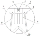
fig. 2 is a schematic front view of an apparatus for controlling the mounting deformation of an optical lens according to the present invention;
FIG. 3 is a perspective view of an upper driving link structure of an apparatus for controlling the mounting deformation of an optical lens according to the present invention;
fig. 4 is an enlarged schematic view of a portion a of fig. 2 of an apparatus for controlling an installation distortion of an optical lens according to the present invention.
In the figure: the device comprises a base plate seat 1, a workbench 2, a side sliding plate 3, a front shaft and a rear shaft 4, an operation button 5, a vertical shaft 6, a lifting plate 7, a vertical column 8, an upper driving connecting rod 9, a lower driving connecting rod 10, a U-shaped column 11, a movable magnet 12, a supporting table 13, an adsorption magnet 14, a frame plate 15, a fixture block 16, a vertical plate 17 and a laser 18.
Detailed Description
The technical solutions in the embodiments of the present invention will be clearly and completely described below with reference to the drawings in the embodiments of the present invention, and it is obvious that the described embodiments are only a part of the embodiments of the present invention, and not all of the embodiments.
Example one
Referring to fig. 1-4, a device for controlling the mounting deformation of an optical lens comprises a base plate seat 1, a workbench 2 is fixedly mounted at the top of the base plate seat 1, the workbench 2 is in a T-shaped arrangement, the workbench 2 is in a hollow arrangement, two side sliding plates 3 are slidably mounted on the inner wall of the bottom of the workbench 2, the two side sliding plates 3 are slidably mounted inside the workbench 2 through sliding rails, the side sliding plates 3 can only slide left and right, a supporting table 13 is placed at the top of the workbench 2, the top of the supporting table 13 can be separated from a movable clamping frame plate 15, the top of the frame plate 15 is similar to the shape of a frame, U-shaped columns 11 are fixedly mounted on the sides of the two side sliding plates 3 away from each other, the two U-shaped columns 11 respectively extend to the upper left side and the upper right side of the workbench 2, the two U-shaped columns 11 are slidably connected with the inner walls on the left side and the right side of the workbench 2, and the end of the two U-shaped columns 11 close to each other is tightly clamped with the left side and the right side of the support platform 13 respectively, here, a heavy clamping support platform 13, in order to facilitate the operation of the two side sliding plates 3 to move towards the side close to each other or the side far away from each other, a vertical shaft 6 is rotatably mounted on the inner wall of the top of the workbench 2, the upper end of the vertical shaft 6 is an optical shaft, the lower end is a threaded shaft, the outer side of the vertical shaft 6 is in threaded connection with a lifting plate 7, here, in order to enable the lifting plate 7 to be locked at any position, an upper driving connecting rod 9 is movably mounted on the front side of the lifting plate 7, the number of the upper driving connecting rods 9 is two, the two upper driving connecting rods 9 are arranged in a splayed shape, lower driving connecting rods 10 are movably mounted at the bottoms of the two upper driving connecting rods 9, the ends of the two lower driving connecting rods 10 close to each other are rotatably connected together, the ends of the two lower driving connecting rods 10 far away from each other are respectively and movably connected with the side close to the two side sliding plates 3, in order to simplify the operation steps and improve the operability, a transmission bevel gear is fixedly sleeved on the outer side of a vertical shaft 6, a front and rear shaft 4 is rotatably installed on the inner wall of the front side of a workbench 2, the front and rear shaft 4 is arranged in the front and rear direction in fig. 2, a driving bevel gear is fixedly sleeved on the outer side of the front and rear shaft 4, the driving bevel gear is engaged with the transmission bevel gear, the reliability of the transmission can be improved, the front end of the front and rear shaft 4 extends to the front side of the workbench 2 and is fixedly installed with an operation button 5, in order to improve the reliability when a support platform 13 is fixed, a vertical plate 17 is fixedly installed on the top of a baseplate seat 1, the top of the vertical plate 17 extends to the upper rear side of a mirror frame plate 15, a laser 18 is fixedly installed on the front side of the vertical plate 17, the laser 18 can emit laser for positioning, the laser 18 is positioned right above the central point of the top of the mirror frame plate 15, and adsorption magnets 14 are fixedly installed on the left side and the right side of the support platform 13, the moving magnets 12 are fixedly mounted at the ends, close to each other, of the two U-shaped columns 11, and the moving magnets 12 and the adsorption magnets 14 located on the same side are in adsorption connection, and the double-clamping support platform 13 is formed.
Example two
The following further improvements are made on the basis of the first embodiment:
in the utility model, in order to position the vertical columns 18 conveniently, the inner wall of the top of the workbench 2 is fixedly provided with two vertical columns 8, the two vertical columns 8 are distributed on the left side and the right side of the vertical shaft 6, the bottoms of the two vertical columns 8 penetrate through the top of the lifting plate 7 and extend to the lower part of the lifting plate 7, the outer sides of the two vertical columns 8 are connected with the lifting plate 7 in a sliding manner, the top of the lifting plate 7 is provided with two sliding holes, and the vertical columns 8 are connected with the corresponding sliding holes in a sliding manner.
In the utility model, in order to facilitate the mounting of the lens frames 15 with different specifications, the bottom of the lens frame 15 is fixedly provided with two clamping blocks 16, the top of the support table 13 is provided with two clamping grooves, the lens frame 15 cannot be separated from the support table 13 under the action of non-manpower, the bottom of the clamping block 16 extends into the corresponding clamping groove and can be movably clamped with the clamping groove, the support table 13 and the lens frame 15 can start the supporting function in the mounting process of the optical lens, and the optical lens cannot be deformed.
In the utility model, in the using process, firstly, a support table 13 is required to be placed on the top of a workbench 2, the front side and the rear side of the support table 13 are respectively positioned on the same vertical line with the front side and the rear side of the workbench 2, at this time, the positions of an adsorption magnet 14 and a moving magnet 12 are aligned, then, an operation button 5 is rotated to rotate a vertical shaft 6, the rotation of the vertical shaft 6 can be converted into the upward movement of a lifting plate 7 due to the threaded connection of the vertical shaft 6 and the lifting plate 7, two lower driving connecting rods 10 can be acted to perform arc motion through two upper driving connecting rods 9, the two lower driving connecting rods 10 can act on two side sliding plates 3 to perform transverse movement towards the mutually close sides, when the operation button 5 can not be rotated any more, the moving magnet 12 and the adsorption magnet 14 on the same side are adsorbed together, two U-shaped columns 11 can also stably clamp the support table 13, and the support table 13 provides stable support for the installation of an optical lens, optical lens piece can not be out of shape when the installation, and compared with the conventional device for controlling optical lens piece installation deformation, the whole process only needs to rotate the operating button 5, so that the operation steps are simplified, time and labor are saved, the efficiency of optical lens piece installation is greatly improved, and the device is worthy of wide popularization and use.
In the description of the present application, it should be further noted that, unless otherwise explicitly stated or limited, the terms "disposed," "mounted," "connected," and "connected" are to be construed broadly and may include, for example, a fixed connection, a detachable connection, an integral connection, a mechanical connection, an electrical connection, a direct connection, a connection through an intermediate medium, and a connection between two elements. The specific meaning of the above terms in the present application can be understood by those of ordinary skill in the art according to specific circumstances.
The above description is only for the preferred embodiment of the present invention, but the scope of the present invention is not limited thereto, and any person skilled in the art should be considered to be within the technical scope of the present invention, and equivalent alternatives or modifications according to the technical solution of the present invention and the inventive concept thereof should be covered by the scope of the present invention.
Claims (6)
1. The utility model provides a device of control optical lens piece installation deformation, includes bottom plate seat (1), the top fixed mounting of bottom plate seat (1) has workstation (2), its characterized in that, workstation (2) set up for cavity, and slidable mounting has two side slide (3) on the bottom inner wall of workstation (2), brace table (13) have been placed at the top of workstation (2), and the top of brace table (13) can break away from the activity card and be equipped with frame plate (15), and the equal fixed mounting in one side that two side slide (3) kept away from each other has U type post (11), and two U type posts (11) extend to the left side top and the right side top of workstation (2) respectively, and the one end that two U type posts (11) are close to each other respectively with the inseparable centre gripping in left side and the right side of brace table (13).
2. The device for controlling the mounting deformation of the optical lens according to claim 1, wherein the vertical shaft (6) is rotatably mounted on the inner wall of the top of the workbench (2), the outer side of the vertical shaft (6) is in threaded connection with the lifting plate (7), the upper driving connecting rods (9) are movably mounted on the front side of the lifting plate (7), the number of the upper driving connecting rods (9) is two, the lower driving connecting rods (10) are movably mounted at the bottoms of the two upper driving connecting rods (9), and one ends of the two lower driving connecting rods (10), which are far away from each other, are respectively movably connected with one side of the two side sliding plates (3), which are close to each other.
3. The device for controlling the mounting deformation of the optical lens according to claim 2, wherein a transmission bevel gear is fixedly sleeved on the outer side of the vertical shaft (6), a front and rear shaft (4) is rotatably mounted on the inner wall of the front side of the workbench (2), a driving bevel gear is fixedly sleeved on the outer side of the front and rear shaft (4) and is engaged with the transmission bevel gear, and the front end of the front and rear shaft (4) extends to the front side of the workbench (2) and is fixedly mounted with the operation button (5).
4. The device for controlling the mounting deformation of the optical lens according to claim 1, wherein two vertical columns (8) are fixedly mounted on the inner wall of the top of the workbench (2), the number of the vertical columns (8) is two, the bottoms of the two vertical columns (8) penetrate through the top of the lifting plate (7) and extend below the lifting plate (7), and the outer sides of the two vertical columns (8) are slidably connected with the lifting plate (7).
5. The device for controlling the mounting deformation of the optical lens according to claim 1, wherein two clamping blocks (16) are fixedly mounted at the bottom of the frame plate (15), two clamping blocks (16) are provided, two clamping slots are provided at the top of the supporting platform (13), two clamping slots are provided, and the bottom of each clamping block (16) extends into the corresponding clamping slot and can be movably clamped with the clamping slot in a detachable manner.
6. The device for controlling the mounting deformation of the optical lens according to claim 1, wherein a vertical plate (17) is fixedly mounted at the top of the base plate (1), the top of the vertical plate (17) extends to the upper portion of the rear side of the frame plate (15), a laser (18) is fixedly mounted at the front side of the vertical plate (17), the laser (18) is located right above the central point of the top of the frame plate (15), the adsorption magnets (14) are fixedly mounted on the left side and the right side of the supporting platform (13), the movable magnets (12) are fixedly mounted at the ends of the two U-shaped columns (11) close to each other, and the movable magnets (12) and the adsorption magnets (14) located on the same side are connected in an adsorption manner.
Priority Applications (1)
| Application Number | Priority Date | Filing Date | Title |
|---|---|---|---|
| CN202122318811.4U CN216052463U (en) | 2021-09-24 | 2021-09-24 | Device for controlling optical lens piece installation deformation |
Applications Claiming Priority (1)
| Application Number | Priority Date | Filing Date | Title |
|---|---|---|---|
| CN202122318811.4U CN216052463U (en) | 2021-09-24 | 2021-09-24 | Device for controlling optical lens piece installation deformation |
Publications (1)
| Publication Number | Publication Date |
|---|---|
| CN216052463U true CN216052463U (en) | 2022-03-15 |
Family
ID=80600265
Family Applications (1)
| Application Number | Title | Priority Date | Filing Date |
|---|---|---|---|
| CN202122318811.4U Active CN216052463U (en) | 2021-09-24 | 2021-09-24 | Device for controlling optical lens piece installation deformation |
Country Status (1)
| Country | Link |
|---|---|
| CN (1) | CN216052463U (en) |
-
2021
- 2021-09-24 CN CN202122318811.4U patent/CN216052463U/en active Active
Similar Documents
| Publication | Publication Date | Title |
|---|---|---|
| CN112832535B (en) | Device and method for positioning and installing reinforcing steel bars for house building | |
| CN216052463U (en) | Device for controlling optical lens piece installation deformation | |
| CN217224209U (en) | Automatic welding device for production of hydraulic oil cylinder | |
| CN213745850U (en) | Liquid crystal display screen with conveniently adjusted height | |
| CN218363045U (en) | Overturning bracket base assembly assembling tool | |
| CN220881231U (en) | Large-cylinder battery cap welding equipment | |
| CN220318019U (en) | Surface treatment device for plastic electroplating | |
| CN220217265U (en) | Coaxial precision seal welding positioning fixture | |
| CN216287963U (en) | Electromagnet core riveting device | |
| CN218697876U (en) | Clamping tool | |
| CN214818374U (en) | Electronic component mounting operation table with multi-directional positioning function | |
| CN218225176U (en) | Service tower welding device of superconducting magnet | |
| CN220078424U (en) | Laboratory integrated form function hoist and mount | |
| CN220388494U (en) | Welding device for electromechanical installation | |
| CN220738329U (en) | Thermosetting thread end material bearing device | |
| CN219584329U (en) | Plug-in carriage plate for carriage | |
| CN217859726U (en) | Auxiliary device for welding steel structure | |
| CN218823233U (en) | Hydraulic support upright jack unbalance loading test frame | |
| CN220819036U (en) | Electric motor car panel board detects frock | |
| CN219405772U (en) | Mucilage material pad printing device | |
| CN214870217U (en) | Novel positive guide pin lifting mechanism | |
| CN220592200U (en) | Automatic screw locking device | |
| CN218910450U (en) | Support frame for heat treatment | |
| CN216967657U (en) | Stator and rotor assembling device for motor production line | |
| CN220448864U (en) | Lightweight multistation circulation mechanism |
Legal Events
| Date | Code | Title | Description |
|---|---|---|---|
| GR01 | Patent grant | ||
| GR01 | Patent grant |