CN216048111U - Double-source integrated air source heat pump unit with total heat recovery - Google Patents
Double-source integrated air source heat pump unit with total heat recovery Download PDFInfo
- Publication number
- CN216048111U CN216048111U CN202121314475.XU CN202121314475U CN216048111U CN 216048111 U CN216048111 U CN 216048111U CN 202121314475 U CN202121314475 U CN 202121314475U CN 216048111 U CN216048111 U CN 216048111U
- Authority
- CN
- China
- Prior art keywords
- valve
- water
- outlet
- heat
- heat exchanger
- Prior art date
- Legal status (The legal status is an assumption and is not a legal conclusion. Google has not performed a legal analysis and makes no representation as to the accuracy of the status listed.)
- Active
Links
Images

Landscapes
- Compression-Type Refrigeration Machines With Reversible Cycles (AREA)
Abstract
The utility model relates to the technical field of heat pump machinery, in particular to a double-source integrated air source heat pump unit with total heat recovery. The high-pressure outlet of the unit compressor is connected with a four-way reversing valve interface d, an interface c is connected with the combined type water-cooled condenser, an interface e is connected with the fin type heat exchanger, and an interface s is connected with the inlet of the gas-liquid separator. The outlet of the composite water-cooled condenser is connected with the shell-and-tube heat exchanger and the liquid side interface of the finned heat exchanger through a pipeline and a valve, and the air side interface of the shell-and-tube heat exchanger is connected with the valve and the inlet of the compressor through a pipeline; the outlet of the gas-liquid separator is connected with the air suction port of the compressor through a pipeline. The utility model can realize free switching of operation modes such as refrigeration, heating, refrigeration and total heat recovery, hot water and the like, and solves the annual requirements of building construction or industrial projects on refrigeration, heating and hot water, thereby realizing multiple purposes of one machine and effectively saving cost.
Description
Technical Field
The utility model relates to the technical field of heat pump machinery, in particular to a double-source integrated air source heat pump unit with total heat recovery.
Background
The conventional central air-conditioning host generally adopts the following two modes:
1) water-cooling water chilling unit
During refrigeration, a water-cooled water chilling unit provides 7 ℃ chilled water for the tail end of an air conditioner such as a fan coil to cool air in a room, a water-cooled condenser transfers condensation heat of a high-temperature and high-pressure refrigerant to cooling water, and the cooling water is conveyed to a cooling tower by a cooling water pump to discharge the heat to outdoor atmosphere. Usually, a water-cooling water chilling unit is placed indoors, a cooling tower is placed outdoors, a longer cooling water circulation pipeline is arranged between the water-cooling water chilling unit and the cooling tower, and a high-power and large-lift cooling water pump is needed to drive cooling water to circulate; and linkage performance between the main machine and the cooling tower and between the main machine and the cooling water pump is poor, so that the actual power consumption of the whole air conditioning system is high, and the energy efficiency is low.
When heating is carried out in winter and transition seasons, additional heating equipment such as a boiler and the like is required to be arranged, so that the energy efficiency is low, the environmental pollution is large, and the operation and maintenance are complex.
The matched civil engineering and the occupation of indoor space cause higher construction cost.
2) Air-cooled cold and hot water unit
When refrigerating in summer, the air-cooled cold and hot water unit discharges a large amount of heat released by high-temperature and high-pressure gas compressed by the compressor in the condensation process to outdoor air through the fin heat exchanger, the specific heat capacity and the density of the air are low, the temperature rise of the air is generally about 10 ℃, and the average temperature of inlet and outlet air is high; meanwhile, the heat transfer coefficient of the air side is low, and the required heat exchange temperature difference is large. Therefore, the condensing temperature of the air-cooled cold and hot water unit is very high, the refrigeration energy efficiency is usually only 2.6-3.0, the energy consumption of the system is overlarge, and the national energy-saving and emission-reducing policy is not met.
When a conventional air-cooled cold and hot water unit performs refrigeration operation in summer, low-pressure refrigerant gas coming out of a water side heat exchanger of an air conditioner generally needs to sequentially pass through a four-way valve and a gas-liquid separator and then enters a compressor, and the on-way resistance and the local resistance of a low-pressure suction pipeline are large, so that the suction pressure of the compressor and the refrigeration efficiency of the unit are reduced.
Whether the water cooling water chilling unit or the air cooling water chilling and heating unit is adopted, a large amount of condensation waste heat needs to be discharged to the outdoor atmosphere environment in summer, so that the outdoor temperature is obviously increased, and the urban heat island effect is caused. If this part of the heat can be recovered for making sanitary/process hot water, the unit can provide sanitary/process hot water free of charge. In a transition season without the cold and heat requirements of the air conditioner, the heat of outdoor air can be absorbed by the fin type heat exchanger, and then sanitary/process hot water is prepared by refrigerating circulation and compressor acting, so that the purpose of one machine with multiple purposes is achieved, and the energy utilization efficiency is improved undoubtedly.
Disclosure of Invention
In order to overcome the defect that the conventional heat pump air conditioner cannot have the functions of summer refrigeration, winter heating and process/sanitary hot water preparation, the double-source integrated air source heat pump unit with total heat recovery is characterized in that the circulation flow of a refrigeration system is optimized, water cooling is adopted for summer refrigeration, the condensation temperature can be reduced by about 14 ℃ compared with that of an air-cooled heat pump, the refrigeration capacity and the refrigeration efficiency of the unit can be obviously improved, low-pressure gas from a shell-and-tube heat exchanger 4 directly enters an air inlet of a compressor, the defect that the refrigeration capacity and the refrigeration efficiency of the unit are reduced due to the fact that the low-pressure gas from a conventional air-cooled heat pump unit sequentially flows through a four-way valve and a gas-liquid separator and then enters the air inlet of the compressor, and the pressure of a low-pressure gas-side part and a pipeline is excessively reduced is overcome, and the air source heat pump is adopted for winter heating, and the heat recovery function is provided for providing annual process or sanitary hot water.
In order to achieve the purpose, the double-source integrated air source heat pump unit with the total heat recovery adopts the following technical scheme: the refrigeration cycle system comprises a compressor 1 connected in a refrigeration cycle loop, wherein a high-pressure outlet of the compressor 1 is connected with a port d of a four-way reversing valve 2, a port c of the four-way reversing valve 2 is connected with a combined water-cooled condenser 3 and a second valve 16, a port e of the four-way reversing valve 2 is connected with a finned heat exchanger 5, a port s of the four-way reversing valve 2 is connected with an inlet of a gas-liquid separator 17, an outlet of the combined water-cooled condenser 3 is connected with a first electromagnetic valve 7, an outlet of the first electromagnetic valve 7 is connected with a first one-way valve 10, an outlet of the first one-way valve 10 is connected with a fourth one-way valve 13, a fifth one-way valve 14, a second electromagnetic valve 8 and a third electromagnetic valve 9, an outlet of the second electromagnetic valve 8 is connected with a first throttle valve 23, an outlet of the first throttle valve 23 and an inlet of the fourth one-way valve 13 are connected with an electromagnetic valve heat exchanger 4, and an outlet of the third electromagnetic valve 9 is connected with a second throttle valve 24, the outlet of the second throttle valve 24 and the inlet of the fifth one-way valve 14 are connected with a liquid side interface of the finned heat exchanger 5, the outlet of the gas-liquid separator 17, the first valve 15 and the air suction port of the compressor 1 are connected with each other, the circulation flow of the refrigeration system is optimized, water cooling is adopted for refrigeration in summer, the condensation temperature can be reduced by about 14 ℃ compared with that of an air-cooled heat pump, the refrigerating capacity and the refrigerating energy efficiency of the unit can be obviously improved, low-pressure gas coming out of the shell-and-tube heat exchanger 4 directly enters the air suction port of the compressor, and an air source heat pump is adopted for heating in winter, and the heat recovery function is provided for providing year-round process or sanitary hot water.
In addition, according to the above embodiment of the present invention, the following additional technical features may be provided:
in some embodiments of the present invention, specifically, the cooling water outlet of the composite water-cooled condenser 3 is connected to a cooling tower 19, the water outlet of the cooling tower 19 is connected to a cooling water pump 20, and the water outlet of the cooling water pump 20 is connected to the cooling water inlet of the composite water-cooled condenser 3.
Specifically, the upper part of the combined type water-cooled condenser 3 is provided with a total heat recovery heat exchange tube bundle, and the lower part of the combined type water-cooled condenser 3 is provided with a cooling water heat exchange tube bundle.
Specifically, the operation of the waterway inside the total heat recovery heat exchange tube bundle is controlled by starting and stopping the hot water pump, and can also be switched and controlled by an electric or pneumatic valve or other types of valves.
Specifically, a sanitary/process hot water loop at the inner side of the heat exchange tube of the total heat recovery heat exchange tube bundle and a cooling water loop at the inner side of the heat exchange tube of the cooling water heat exchange tube bundle are mutually independent.
Specifically, the shell-and-tube heat exchanger 4 may be a dry evaporator, a flooded evaporator, a falling film evaporator or other type of evaporator.
Specifically, the first valve 15 and the second valve 16 may be electric valves, pneumatic valves, manual valves or other types of valves, and the operation of the waterway inside the heat exchange tubes of the total heat recovery heat exchange tube bundle in the composite water-cooled condenser 3 may be controlled by switching the hot water three-way valve 22, which may use electric valves or pneumatic valves or other types of valves.
The utility model has the following advantages: the single unit can realize the water-cooling condensation mode in summer, the refrigeration efficiency is high, the condensation waste heat generated by refrigeration is recovered to prepare sanitary/process hot water, and the unit can provide free sanitary/process hot water. In winter, an air source heat pump operation mode is adopted, so that not only can heat be supplied, but also domestic hot water can be prepared. In the transition season without the cold and heat requirement of the air conditioner, the heat of outdoor air can be absorbed through the finned heat exchanger, and then sanitary/process hot water is prepared by applying work through the refrigeration cycle and the compressor. Thereby achieving the purpose of one machine with multiple purposes and effectively improving the energy utilization efficiency.
Drawings
FIG. 1 is a schematic diagram of a structure according to one embodiment of the present invention;
FIG. 2 is a schematic diagram of a structure according to one embodiment of the present invention;
FIG. 3 is a schematic diagram of a structure according to one embodiment of the present invention;
wherein, 1, a compressor; 2. a four-way reversing valve; 3. a composite water-cooled condenser; 4. a shell and tube heat exchanger; 5. a finned heat exchanger; 6. a throttle valve; 7. a first solenoid valve; 8. a second solenoid valve; 9. a third electromagnetic valve; 10. a first check valve; 11. a second one-way valve; 12. a third check valve; 13. a fourth check valve; 14. a fifth check valve; 15. a first valve; 16. a second valve; 17. a gas-liquid separator; 18. a fifth valve; 19. a cooling tower; 20. a cooling water pump; 21. a hot water pump; 22. a hot water three-way valve; 23. a first throttle valve; 24. a second throttle valve; 25. a third valve; 26. and a fourth valve.
Detailed Description
Reference will now be made in detail to embodiments of the present invention, examples of which are illustrated in the accompanying drawings, wherein like or similar reference numerals refer to the same or similar elements or elements having the same or similar function throughout. The embodiments described below with reference to the drawings are illustrative and intended to be illustrative of the utility model and are not to be construed as limiting the utility model.
In the description of the present invention, it is to be understood that the terms "first", "second" and the like are used for descriptive purposes only and are not to be construed as indicating or implying relative importance or implying any number of technical features indicated. Thus, a feature defined as "first" or "second" may explicitly or implicitly include one or more of that feature. In the description of the present invention, "a plurality" means two or more, for example, two, three, etc., unless specifically defined otherwise.
In the present invention, unless otherwise expressly specified or limited, the terms "connected," "communicating," and the like are to be construed broadly, e.g., as meaning fixedly connected, detachably connected, or integrally formed; can be mechanical connection and electrical connection; may be directly connected, or indirectly connected through an intermediate; there may be communication within two elements or an interaction of two elements unless otherwise expressly limited. The specific meanings of the above terms in the present invention can be understood by those skilled in the art according to specific situations.
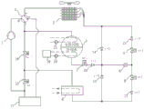
Referring to fig. 1 for detailed description of one aspect of the utility model, the utility model provides a dual-source integrated air source heat pump unit with total heat recovery, which comprises a compressor 1 connected in a refrigeration cycle loop, a high-pressure outlet of the compressor 1 is connected with a four-way reversing valve 2, a connector c of the four-way reversing valve 2 is connected with a composite water-cooled condenser 3 and a second valve 16, a connector e of the four-way reversing valve 2 is connected with a finned heat exchanger 5, a connector s of the four-way reversing valve 2 is connected with an inlet of a gas-liquid separator 17, an outlet of the composite water-cooled condenser 3 is connected with a first electromagnetic valve 7, an outlet of the first electromagnetic valve 7 is connected with a first one-way valve 10, an outlet of the first one-way valve 10 is connected with a throttle valve 6, a fourth one-way valve 13 and a fifth one-way valve 14, an outlet of the throttle valve 6 is connected with a second electromagnetic valve 8 and a third electromagnetic valve 9, an outlet of the second electromagnetic valve 8 is connected with a second one-way valve 11, the outlet of the second check valve 11 and the inlet of the fourth check valve 13 are connected with the shell-and-tube heat exchanger 4, the air-side interface of the shell-and-tube heat exchanger 4 is connected with a first valve 15 and a second valve 16, the outlet of the third electromagnetic valve 9 is connected with a third check valve 12, the outlet of the third check valve 12 and the inlet of the fifth check valve 14 are connected with the liquid-side interface of the finned heat exchanger 5, and the outlet of the gas-liquid separator 17 is connected with the first valve 15 and the air suction port of the compressor 1.
And the cooling water outlet of the composite water-cooled condenser 3 is connected with a cooling tower 19, the water outlet of the cooling tower 19 is connected with a cooling water pump 20, and the water outlet of the cooling water pump 20 is connected with the cooling water inlet of the composite water-cooled condenser 3.
The upper part of the composite water-cooled condenser 3 is provided with a total heat recovery heat exchange tube bundle, sanitary/process hot water on the inner side of a heat exchange tube absorbs heat discharged by a high-temperature and high-pressure gas refrigerant on the outer side of the heat exchange tube in the condensation process when the composite water-cooled condenser is operated in a hot water mode or a refrigerating and heating water mode, and the sanitary/process hot water leaves the composite water-cooled condenser 3 after the temperature of the sanitary/process hot water is increased and is led to the heat-required tail end of a user. The operation of the sanitary/process hot water path in the combined type water-cooled condenser 3 can be controlled by starting and stopping the hot water pump 21, and can also be switched and controlled by an electric valve, a pneumatic valve or other types of valves.
The lower part of the composite water-cooled condenser 3 is provided with a cooling water heat exchange tube bundle, cooling water on the inner side of a heat exchange tube absorbs heat discharged by a high-temperature and high-pressure gas refrigerant on the outer side of the heat exchange tube in the condensation process during the refrigeration mode operation, and the cooling water leaves the composite water-cooled condenser 3 after the temperature of the cooling water rises and is led to a cooling tower.
According to an embodiment of the present invention, the sanitary/process hot water loop inside the heat exchange tubes of the total heat recovery heat exchange tube bundle and the cooling water loop inside the heat exchange tubes of the cooling water heat exchange tube bundle are independent from each other, and the high temperature and high pressure gas refrigerant entering the top of the composite water cooled condenser 3 flows through the total heat recovery heat exchange tube bundle first and then flows through the cooling water heat exchange tube bundle, and is condensed into high pressure liquid after discharging heat to the sanitary/process hot water or cooling water.
According to one embodiment of the utility model, water cooling is adopted for cooling in summer, the condensing temperature can be reduced by about 14 ℃ compared with an air-cooled heat pump, the refrigerating capacity and the refrigerating energy efficiency of the unit can be obviously improved, and low-pressure gas from the shell-and-tube heat exchanger 4 directly enters the air suction port of the compressor, so that the defect that the refrigerating capacity and the refrigerating energy efficiency of the unit are reduced due to the fact that the low-pressure air suction side part and the pipeline have overlarge pressure drop because the conventional air-cooled heat pump unit needs to sequentially pass through the four-way valve and the gas-liquid separator and then enter the air suction port of the compressor can be effectively overcome.
According to an embodiment of the present invention, the first valve 15 and the second valve 16 may be electrically operated valves or pneumatic operated valves, and may also be manual valves or other types of valves.
The utility model provides a double-source integrated air source heat pump unit with total heat recovery, which is characterized in that the working states and the refrigerant flows of all components of a refrigerating mode, a refrigerating and heating water mode, a heating mode and a hot water mode of the unit are as follows:
in a refrigeration mode, the working states of all the components are as follows: the four-way reversing valve 2 and the third electromagnetic valve 9 are powered off, the first electromagnetic valve 7 and the second electromagnetic valve 8 are powered on, the first valve 15 is opened, the second valve 16 is closed, the cooling tower 19 and the cooling water pump 20 are in a running state, the fan of the finned heat exchanger 5 stops running, the hot water pump 21 stops running, and the air-conditioning water channel in the shell-and-tube heat exchanger 4 runs.
In the cooling mode, the refrigerant flow: the high-temperature high-pressure gas refrigerant discharged by the compressor 1 sequentially enters the composite water-cooled condenser 3 through the interface d and the interface c of the four-way reversing valve 2, flows through the outer side of the heat exchange tube of the total heat recovery heat exchange tube bundle, exchanges heat with cooling water on the inner side of the heat exchange tube with relatively low temperature on the outer side of the heat exchange tube of the cooling water heat exchange tube bundle, and is condensed into high-pressure liquid after being discharged to the cooling water. The high-pressure liquid enters the throttling valve 6 after sequentially passing through the first electromagnetic valve 7 and the first one-way valve 10, is throttled and depressurized to be low-temperature and low-pressure gas-liquid mixed refrigerant, then enters the shell-and-tube heat exchanger 4 through the second electromagnetic valve 8 and the second one-way valve 11, absorbs the heat of the air conditioner chilled water to cool the refrigerant, evaporates the refrigerant to be low-pressure gas, then returns to the air suction port of the compressor 1 through the first valve 15, is compressed to be high-temperature and high-pressure gas refrigerant by the compressor 1, and is repeatedly circulated.
The cooling water is conveyed to a cooling tower 19 by a cooling water pump after absorbing the condensation heat of the high-temperature high-pressure gas refrigerant, the temperature is reduced after the heat is discharged to outdoor air in the cooling tower, then the cooling water is conveyed to the inner side of a heat exchange pipe of a cooling water heat exchange pipe bundle at the lower part of the composite water-cooled condenser 3 by a cooling water pump 20, the cooling water is heated after absorbing the condensation heat discharged by the high-temperature high-pressure gas refrigerant at the outer side of the heat exchange pipe, and the process is repeated.
The air-conditioning chilled water with lower temperature from the shell-and-tube heat exchanger 4 flows to the tail end of the air conditioner of a user, cools the circulating air flowing through the tail end of the air conditioner to release cold energy, then the temperature is increased, the air-conditioning chilled water is conveyed back to the shell-and-tube heat exchanger 4 by the air-conditioning water pump to exchange heat with the low-temperature low-pressure gas-liquid mixed refrigerant throttled by the throttle valve 6, the temperature of the chilled water is reduced after the chilled water is cooled by the refrigerant, and the circulation is repeated.
During the second refrigeration and water heating mode, the working states of all the parts are as follows: the four-way reversing valve 2 and the third electromagnetic valve 9 are powered off, the first electromagnetic valve 7 and the second electromagnetic valve 8 are powered on, the first valve 15 is opened, the second valve 16 is closed, the cooling tower 19 and the cooling water pump 20 stop running, the hot water pump 21 runs, the fan of the finned heat exchanger 5 stops running, and the air-conditioning water channel in the shell-and-tube heat exchanger 4 runs.
In the cooling and heating water mode, the refrigerant flow is as follows: the high-temperature high-pressure gas refrigerant discharged by the compressor 1 sequentially enters the composite water-cooled condenser 3 through the interface d and the interface c of the four-way reversing valve 2, exchanges heat with the process/sanitary hot water on the inner side of the heat exchange tube with relatively low temperature on the outer side of the heat exchange tube of the total heat recovery heat exchange tube bundle, and is condensed into high-pressure liquid after the condensation heat is discharged to the process/sanitary hot water. The high-pressure liquid flows through the outer side of the cooling water heat exchange tube bundle and then leaves the composite water-cooled condenser 3, then sequentially passes through the first electromagnetic valve 7 and the first one-way valve 10 and then enters the throttle valve 6, is throttled and depressurized into a low-temperature low-pressure gas-liquid mixed refrigerant, then enters the shell-and-tube heat exchanger 4 through the second electromagnetic valve 8 and the second one-way valve 11, absorbs the heat of the air-conditioner chilled water to cool the refrigerant, evaporates the refrigerant into low-pressure gas, then returns to the air suction port of the compressor 1 through the first valve 15, is compressed into a high-temperature high-pressure gas refrigerant by the compressor 1, and repeats the above steps.
The process/sanitary hot water which absorbs the condensation heat of the high-temperature and high-pressure gas refrigerant and has the temperature rising is conveyed to the heat-requiring end of a user, the temperature of the process/sanitary hot water is reduced after the heat is discharged to the heat-requiring end, then the process/sanitary hot water is conveyed to the inner side of the heat exchange tube of the total heat recovery heat exchange tube bundle at the upper part of the composite water-cooled condenser 3, the temperature rises after the condensation heat discharged by the high-temperature and high-pressure gas refrigerant outside the heat exchange tube is absorbed, and the process/sanitary hot water is repeatedly circulated.
The air-conditioning chilled water with lower temperature from the shell-and-tube heat exchanger 4 flows to the tail end of the user air conditioner, the temperature is increased after cold energy is released, the air-conditioning chilled water is conveyed back to the shell-and-tube heat exchanger 4 by the air-conditioning water pump to exchange heat with the low-temperature low-pressure gas-liquid mixed refrigerant throttled by the throttle valve 6, the temperature of the chilled water is reduced after the chilled water is cooled by the refrigerant, and the circulation is repeated.
In the three heating modes, the working states of all the components are as follows: the four-way reversing valve 2, the first electromagnetic valve 7 and the second electromagnetic valve 8 are powered off, the third electromagnetic valve 9 is powered on, the first valve 15 is closed, the second valve 16 is opened, the cooling tower 19 and the cooling water pump 20 stop running, the fan of the finned heat exchanger 5 runs, the air-conditioning water channel in the shell-and-tube heat exchanger 4 runs, and the hot water pump 21 stops running;
in the heating mode, the refrigerant flow: the high-temperature high-pressure gas discharged by the compressor 1 sequentially passes through the interface d and the interface c of the four-way reversing valve 2 and the second valve 16 to enter the shell-and-tube heat exchanger 4 to exchange heat with the air-conditioning hot water with relatively low temperature, a large amount of condensation heat is discharged to the air-conditioning hot water to heat and heat the air-conditioning hot water, then the condensation heat is condensed into high-pressure liquid, then the high-pressure liquid enters the throttling valve 6 through the fourth one-way valve 13 to be throttled and decompressed into low-temperature low-pressure gas-liquid mixed refrigerant, then the low-temperature low-pressure gas-liquid mixed refrigerant enters the fin type heat exchanger 5 through the third electromagnetic valve 9 and the third one-way valve 12 to exchange heat with outdoor air with relatively high temperature, the low-pressure gas refrigerant is evaporated after absorbing the outdoor air heat, then the low-pressure gas refrigerant sequentially passes through the interface e and the interface s of the four-way reversing valve 2 and the gas-liquid separator 17 to return to the air suction port of the compressor 1, and is compressed into the high-temperature high-pressure gas refrigerant by the compressor 1, and the repeated circulation is carried out.
The air-conditioning hot water with higher temperature coming out of the shell-and-tube heat exchanger 4 is delivered to the end of the air conditioner of a user, the temperature is reduced after the heat is discharged to the circulating air flowing through the end of the air conditioner, and the air-conditioning hot water is delivered back to the shell-and-tube heat exchanger 4 by the air-conditioning water pump, absorbs the condensation heat of the high-temperature and high-pressure gas refrigerant, is heated into the air-conditioning hot water with higher temperature, and is repeatedly circulated.
When defrosting in the heating mode, the working states of all the components are as follows: the first electromagnetic valve 7 and the third electromagnetic valve 9 are powered off, the four-way reversing valve 2 and the second electromagnetic valve 8 are powered on, the first valve 15 is closed, the second valve 16 is opened, the cooling tower 19 and the cooling water pump 20 stop running, the fan of the finned heat exchanger 5 stops running, the air-conditioning water channel in the shell-and-tube heat exchanger 4 runs, and the hot water pump 21 stops running.
During defrosting in the heating mode, the refrigerant flow is as follows: high-temperature and high-pressure gas discharged by the compressor 1 sequentially enters the finned heat exchanger 5 through the interface d and the interface e of the four-way reversing valve 2, a large amount of condensation heat is transferred to frost or ice on the surface of fins, so that the frost or ice absorbs heat and melts into water to be separated from the surfaces of the fins so as to realize a defrosting function, the high-pressure gas refrigerant is condensed into high-pressure liquid, then enters the throttling valve 6 through the fifth one-way valve 14, is throttled and depressurized into low-temperature and low-pressure gas-liquid mixed refrigerant, then enters the shell-and-tube heat exchanger 4 through the second electromagnetic valve 8 and the second one-way valve 11 sequentially, exchanges heat with air-conditioning hot water with higher temperature, evaporates into low-pressure gas after absorbing the heat of the air-conditioning hot water, then returns to the air suction port of the compressor 1 through the second valve 16, the interface c and the interface s of the four-way reversing valve 2 and the gas-liquid separator 17 sequentially, and is compressed into the high-temperature and high-pressure gas refrigerant by the compressor 1, the circulation is repeated until the defrosting is finished.
In the four hot water modes, the working states of all the components are as follows: the four-way reversing valve 2 and the second electromagnetic valve 8 are powered off, the first electromagnetic valve 7 and the third electromagnetic valve 9 are powered on, the first valve 15 and the second valve 16 are closed, the cooling tower 19 and the cooling water pump 20 stop running, the hot water pump 21 runs, the air-conditioning water channel in the shell-and-tube heat exchanger 4 stops running, and the fan of the finned heat exchanger 5 runs.
In the hot water mode, the refrigerant flow: the high-temperature high-pressure gas discharged by the compressor 1 sequentially enters the composite water-cooled condenser 3 through the interface d and the interface c of the four-way reversing valve 2, exchanges heat with sanitary/process hot water with relatively low temperature at the outer side of a heat exchange pipe of the total heat recovery heat exchange pipe bundle, discharges a large amount of condensation heat to the sanitary/process hot water, is condensed into high-pressure liquid after being heated and heated, then leaves the composite water-cooled condenser 3 after flowing through a cooling water heat exchange pipe at the lower part of the composite water-cooled condenser 3, then enters the throttling valve 6 through the first electromagnetic valve 7 and the first one-way valve 10 in sequence, is throttled and depressurized into low-temperature low-pressure gas-liquid mixed refrigerant, then enters the finned heat exchanger 5 through the third electromagnetic valve 9 and the third one-way valve 12, exchanges heat with outdoor air with relatively high temperature, and is evaporated into low-pressure gas after absorbing the outdoor air heat, then returns to the air suction port of the compressor 1 through the interface e and the interface s of the four-way reversing valve 2 and the gas-liquid separator 17 in sequence, is compressed into high-temperature and high-pressure gas refrigerant by the compressor 1, and is circulated repeatedly in the way.
The sanitary/process hot water with lower temperature enters the inner side of the heat exchange tube of the total heat recovery heat exchange tube bundle at the upper part of the combined type water-cooled condenser 3, the temperature rises after absorbing the condensation heat discharged by the high-temperature high-pressure gas refrigerant at the outer side of the heat exchange tube, then the sanitary/process hot water is conveyed to the end needing heat of a user, the temperature of the sanitary/process hot water is reduced after the heat is discharged to the end needing heat, then the sanitary/process hot water is conveyed to the inner side of the heat exchange tube of the total heat recovery heat exchange tube bundle at the upper part of the combined type water-cooled condenser 3, and the circulation is repeated.
During defrosting in a hot water mode, the working states of all the components are as follows: the first electromagnetic valve 7 and the third electromagnetic valve 9 are powered off, the four-way reversing valve 2 and the second electromagnetic valve 8 are powered on, the first valve 15 is opened, the second valve 16 is closed, the cooling tower 19 and the cooling water pump 20 stop running, the fan of the finned heat exchanger 5 stops running, and the air-conditioning water channel in the shell-and-tube heat exchanger 4 runs.
During defrosting in a hot water mode, a refrigerant flow: the high-temperature high-pressure gas refrigerant discharged by the compressor 1 sequentially enters the finned heat exchanger 5 through the interface d and the interface e of the four-way reversing valve 2, a large amount of condensation heat is discharged to frost or ice on the surface of the fin, the frost or ice is melted into water through heat absorption and is separated from the surface of the fin to achieve a defrosting function, the high-pressure gas is condensed into high-pressure liquid, then enters the throttling valve 6 through the fifth one-way valve 14, is throttled and depressurized into low-temperature low-pressure gas-liquid two-phase refrigerant, enters the shell-and-tube heat exchanger 4 through the second electromagnetic valve 8 and the second one-way valve 11, absorbs the water heat of the air conditioner, is evaporated into low-pressure gas, then returns to the air suction port of the compressor 1 through the first valve 15, is compressed into the high-temperature high-pressure gas refrigerant by the compressor 1, and the cycle is repeated.
The air conditioning water entering the shell-and-tube heat exchanger 4 releases heat to the throttled low-temperature low-pressure gas-liquid mixed refrigerant, then the temperature is reduced, the air conditioning water is driven by an air conditioning water pump to return to the shell-and-tube heat exchanger 4 after passing through the air conditioning tail end and an air conditioning water loop, and the repeated circulation is carried out until defrosting is finished.
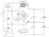
Referring to fig. 2, another aspect of the utility model is described in detail, the dual-source integrated air source heat pump unit with total heat recovery provided by the utility model comprises a compressor 1 connected in a refrigeration cycle loop, a high-pressure outlet of the compressor 1 is connected with a four-way reversing valve 2, a connector c of the four-way reversing valve 2 is connected with a composite water-cooled condenser 3 and a second valve 16, a connector e of the four-way reversing valve 2 is connected with a finned heat exchanger 5, a connector s of the four-way reversing valve 2 is connected with a gas-liquid separator 17, an outlet of the composite water-cooled condenser 3 is connected with a first electromagnetic valve 7, an outlet of the first electromagnetic valve 7 is connected with a first one-way valve 10, an outlet of the first one-way valve 10 is connected with a fourth one-way valve 13, a fifth one-way valve 14, a second electromagnetic valve 8 and a third electromagnetic valve 9, an outlet of the second electromagnetic valve 8 is connected with a first throttle valve 23, and an inlet of the first throttle valve 23 and the fourth one-way valve 13 are connected with a shell-tube heat exchanger 4, the air side interface of the shell-and-tube heat exchanger 4 is connected with a first valve 15 and a second valve 16, the outlet of the third electromagnetic valve 9 is connected with a second throttle valve 24, the outlet of the second throttle valve 24 and the inlet of the fifth one-way valve 14 are connected with the liquid side interface of the finned heat exchanger 5, and the outlet of the gas-liquid separator 17 is connected with the first valve 15 and the suction port of the compressor 1.
The cooling water outlet of the combined type water-cooled condenser 3 is connected with a cooling tower 19, a cooling water pump 20 at the water outlet of the cooling tower 19 is arranged, and the water outlet of the cooling water pump 20 is connected with the cooling water inlet of the combined type water-cooled condenser 3. The water inlet and the water outlet of the process/sanitary hot water of the combined type water-cooled condenser 3 are connected with a hot water three-way valve 22.
The utility model provides a double-source integrated air source heat pump unit with total heat recovery, which is characterized in that the working states and the refrigerant flows of all components of a refrigerating mode, a refrigerating and heating water mode, a heating mode and a hot water mode of the unit are as follows:
in a refrigeration mode, the working states of all the components are as follows: the four-way reversing valve 2 and the third electromagnetic valve 9 are powered off, the first electromagnetic valve 7 and the second electromagnetic valve 8 are powered on, the first valve 15 is opened, the second valve 16 is closed, the cooling tower 19 and the cooling water pump 20 are in a running state, an air-conditioning water channel in the shell-and-tube heat exchanger 4 runs, and the hot water three-way valve 22 cuts off the flow of hot water in the heat exchange tubes of the total heat recovery heat exchange tube bundle at the upper part of the combined type water-cooled condenser 3.
In the cooling mode, the refrigerant flow: the compressor 1- > an interface d- > of the four-way reversing valve 2- > an interface c- > of the four-way reversing valve 2- > the composite water-cooled condenser 3- > a first electromagnetic valve 7- > a first one-way valve 10- > a second electromagnetic valve 8- > a first throttling valve 23- > the shell-and-tube heat exchanger 4- > a first valve 15- > the compressor 1.
During the second refrigeration and water heating mode, the working states of all the parts are as follows: the four-way reversing valve 2 and the third electromagnetic valve 9 are powered off, the first electromagnetic valve 7 and the second electromagnetic valve 8 are powered on, the first valve 15 is opened, the second valve 16 is closed, the cooling tower 19 and the cooling water pump 20 stop running, the air-conditioning water channel in the shell-and-tube heat exchanger 4 runs, and the hot water three-way valve 22 maintains the flow of hot water in the heat exchange tube of the total heat recovery heat exchange tube bundle of the combined water-cooled condenser 3.
In the cooling and heating water mode, the refrigerant flow is as follows: the compressor 1- > an interface d- > of the four-way reversing valve 2- > an interface c- > of the four-way reversing valve 2- > the composite water-cooled condenser 3- > a first electromagnetic valve 7- > a first one-way valve 10- > a second electromagnetic valve 8- > a first throttling valve 23- > the shell-and-tube heat exchanger 4- > a first valve 15- > the compressor 1.
In the three heating modes, the working states of all the components are as follows: the four-way reversing valve 2, the first electromagnetic valve 7 and the second electromagnetic valve 8 are powered off, the third electromagnetic valve 9 is powered on, the first valve 15 is closed, the second valve 16 is opened, the cooling tower 19 and the cooling water pump 20 stop running, the fan of the finned heat exchanger 5 runs, the air-conditioning waterway in the shell-and-tube heat exchanger 4 runs, and the hot water three-way valve 22 cuts off the flow of hot water in the heat exchange tube of the total heat recovery heat exchange tube bundle of the combined water-cooled condenser 3;
in the heating mode, the refrigerant flow: the compressor 1- > a connector d- > of the four-way reversing valve 2- > a connector c- > a second valve 16- > a shell-and-tube heat exchanger 4- > a fourth one-way valve 13- > a third electromagnetic valve 9- > a second throttling valve 24- > a fin-type heat exchanger 5- > a connector e- > of the four-way reversing valve 2- > a connector s- > a gas-liquid separator 17- > the compressor 1.
In the four hot water modes, the working states of all the components are as follows: the four-way reversing valve 2 and the third electromagnetic valve 8 are powered off, the first electromagnetic valve 7 and the second electromagnetic valve 9 are powered on, the first valve 15 and the second valve 16 are closed, the cooling tower 19 and the cooling water pump 20 stop running, the air-conditioning waterway in the shell-and-tube heat exchanger 4 does not run, and the hot water three-way valve 22 keeps hot water in the heat exchange tube of the total heat recovery heat exchange tube bundle of the combined water-cooled condenser 3 flowing.
In the hot water mode, the refrigerant flow: the compressor 1- > a connector d- > of the four-way reversing valve 2- > a connector c- > a composite water-cooled condenser 3- > a first electromagnetic valve 7- > a first one-way valve 10- > a third electromagnetic valve 9- > a second throttling valve 24- > a fin type heat exchanger 5- > a connector e- > of the four-way reversing valve 2- > a connector s- > a gas-liquid separator 17- > the compressor 1.
Referring to fig. 3, another aspect of the present invention is described in detail, the dual-source integrated air source heat pump unit with total heat recovery provided by the present invention includes a compressor 1 connected in a refrigeration cycle loop, a high pressure outlet of the compressor 1 is connected with a four-way reversing valve 2, a connector c of the four-way reversing valve 2 is connected with a composite water-cooled condenser 3 with total heat recovery and a second valve 16, a connector e of the four-way reversing valve 2 is connected with a finned heat exchanger 5, a connector s of the four-way reversing valve 2 is connected with a gas-liquid separator 17, an outlet of the composite water-cooled condenser 3 is connected with a third valve 25, an outlet of the third valve 25 is connected with a fourth check valve 13, a fifth check valve 14, a fourth valve 26 and a fifth valve 18, an outlet of the fourth valve 26 and an inlet of the fourth check valve 13 are connected with a shell-tube heat exchanger 4, an air side connector of the shell-tube heat exchanger 4 is connected with the first valve 15 and the second valve 16, the outlet of the fifth valve 18 and the inlet of the fifth one-way valve 14 are connected with a liquid side interface of the finned heat exchanger 5, and the outlet of the gas-liquid separator 17 is connected with the first valve 15 and the suction port of the compressor 1.
The cooling tower 19 is connected to 3 cooling water delivery ports of combined type water cooled condenser of taking total heat recovery, cooling water pump 20 is connected to 19 delivery ports of cooling tower, cooling water pump 20's delivery port with 3 water inlets of combined type water cooled condenser link to each other, 3 total heat recovery hot water inlets of combined type water cooled condenser and delivery port connection hot water three-way valve 22.
According to an embodiment of the present invention, the shell-and-tube heat exchanger 4 may be a dry evaporator or a flooded evaporator, or may be a falling film evaporator or other type of evaporator.
According to a specific embodiment of the present invention, the first valve 15 and the second valve 16 may be electrically or pneumatically operated valves, and may also be manual valves or other types of valves.
According to an embodiment of the present invention, the operation of the full heat recovery hot water path in the composite water-cooled condenser 3 is controlled by switching the three-way valve, which may be an electric valve or a pneumatic valve or other valves.
According to an embodiment of the present invention, the refrigerant from the third valve 25 is branched into 2 paths, and throttled by the fourth valve 26 and the fifth valve 18, and the fourth valve 26 and the fifth valve 18 may be electronic expansion valves or electric ball valves, or electric butterfly valves or other types of valves.
The third valve 25 may be an electrically or pneumatically actuated valve, according to a specific embodiment of the present invention, although other types of valves may be used.
The utility model provides a double-source integrated air source heat pump unit with total heat recovery, which is characterized in that the working states and the refrigerant flows of all components of a refrigerating mode, a refrigerating and heating water mode, a heating mode and a hot water mode of the unit are as follows:
in a refrigeration mode, the working states of all the components are as follows: the four-way reversing valve 2 is powered off, the fifth valve 18 is closed, the fourth valve 26 is opened, the first valve 15 is opened, the second valve 16 is closed, the third valve 25 is opened, the cooling tower 19 and the cooling water pump 20 are in a running state, an air-conditioning water channel in the shell-and-tube heat exchanger 4 runs, and the three-way valve 22 cuts off the flow of hot water in the heat exchange tube of the total heat recovery heat exchange tube bundle of the combined water-cooled condenser 3.
In the cooling mode, the refrigerant flow: the compressor 1- > an interface d- > of the four-way reversing valve 2- > an interface c- > of the four-way reversing valve 2- > the composite water-cooled condenser 3- > the third valve 25- > the fourth valve 26- > the shell-and-tube heat exchanger 4- > the first valve 15- > the compressor 1.
During the second refrigeration and water heating mode, the working states of all the parts are as follows: the four-way reversing valve 2 is powered off, the first valve 15, the third valve 25 and the fourth valve 26 are opened, the second valve 16 and the fifth valve 18 are closed, the cooling tower 19 and the cooling water pump 20 stop running, the air-conditioning waterway in the shell-and-tube heat exchanger 4 runs, and the hot water three-way valve 22 maintains the flow of hot water in the heat exchange tubes of the total heat recovery heat exchange tube bundle of the combined water-cooled condenser 3.
In the cooling and heating water mode, the refrigerant flow is as follows: the compressor 1- > an interface d- > of the four-way reversing valve 2- > an interface c- > of the four-way reversing valve 2- > the composite water-cooled condenser 3- > the third valve 25- > the fourth valve 26- > the shell-and-tube heat exchanger 4- > the first valve 15- > the compressor 1.
In the three heating modes, the working states of all the components are as follows: the four-way reversing valve 2 is powered off, the first valve 15, the third valve 25 and the fourth valve 26 are closed, the second valve 16 and the fifth valve 18 are opened, the cooling tower 19 and the cooling water pump 20 stop running, an air conditioner water channel in the shell-and-tube heat exchanger 4 runs, and the three-way valve 22 cuts off the flow of hot water in the heat exchange tube of the total heat recovery heat exchange tube bundle.
In the heating mode, the refrigerant flow: the compressor 1- > an interface d- > of the four-way reversing valve 2- > an interface c- > of the four-way reversing valve 2- > a second valve 16- > a shell-and-tube heat exchanger 4- > a fourth check valve 13- > a fifth valve 18- > a fin-type heat exchanger 5- > an interface e- > of the four-way reversing valve 2- > an interface s- > a gas-liquid separator 17- > the compressor 1.
In the four hot water modes, the working states of all the components are as follows: the four-way reversing valve 2 is powered off, the first valve 15, the second valve 16 and the fourth valve 26 are closed, the third valve 25 and the fifth valve 18 are opened, the cooling tower 19 and the cooling water pump 20 stop running, the air-conditioning water channel in the shell-and-tube heat exchanger 4 does not run, and the three-way valve 22 maintains the flowing of hot water in the heat exchange tube of the total heat recovery heat exchange tube bundle.
A refrigerant flow path: the compressor 1- > an interface d- > of the four-way reversing valve 2- > an interface c- > of the four-way reversing valve 2- > the composite water-cooled condenser 3- > the third valve 25- > the fifth valve 18- > the fin-type heat exchanger 5- > an interface e- > of the four-way reversing valve 2- > an interface s- > the gas-liquid separator 17- > the compressor 1.
While embodiments of the present invention have been shown and described above, it should be understood that the above embodiments are exemplary and should not be taken as limiting the utility model. Various changes and modifications may be made to the utility model without departing from the spirit and scope of the utility model, and such changes and modifications are intended to be within the scope of the utility model as claimed.
Claims (7)
1. The double-source integrated air source heat pump unit with total heat recovery is characterized by comprising a compressor (1) connected in a refrigeration cycle loop, wherein a high-pressure outlet of the compressor (1) is connected with a four-way reversing valve (2) interface d, a four-way reversing valve (2) interface c is connected with a combined water-cooled condenser (3) and a second valve (16), a four-way reversing valve (2) interface e is connected with a finned heat exchanger (5), a four-way reversing valve (2) interface s is connected with an inlet of a gas-liquid separator (17), an outlet of the combined water-cooled condenser (3) is connected with a first electromagnetic valve (7), an outlet of the first electromagnetic valve (7) is connected with a first one-way valve (10), an outlet of the first one-way valve (10) is connected with a fourth one-way valve (13), a fifth one-way valve (14), a second electromagnetic valve (8) and a third electromagnetic valve (9), the outlet of the second electromagnetic valve (8) is connected with a first throttling valve (23), the outlet of the first throttling valve (23) and the inlet of the fourth one-way valve (13) are connected with the shell-and-tube heat exchanger (4), the outlet of the third electromagnetic valve (9) is connected with a second throttling valve (24), the outlet of the second throttling valve (24) and the inlet of the fifth one-way valve (14) are connected with a liquid side interface of the finned heat exchanger (5), and the outlet of the gas-liquid separator (17) is connected with the first valve (15) and an air suction port of the compressor (1).
2. The dual-source integrated air source heat pump unit with total heat recovery of claim 1, wherein the cooling water outlet of the combined type water-cooled condenser (3) is connected with a cooling tower (19), the water outlet of the cooling tower (19) is connected with a cooling water pump (20), and the water outlet of the cooling water pump (20) is connected with the cooling water inlet of the combined type water-cooled condenser (3).
3. The dual-source integrated air source heat pump unit with total heat recovery function according to claim 2, wherein the composite water-cooled condenser (3) is provided with a total heat recovery heat exchange tube bundle at the upper part thereof, and the composite water-cooled condenser (3) is provided with a cooling water heat exchange tube bundle at the lower part thereof.
4. The dual-source integrated air source heat pump unit with total heat recovery of claim 3, wherein the operation of the waterway inside the total heat recovery heat exchange tube bundle is controlled by starting and stopping the hot water pump or by switching the electric or pneumatic valve.
5. The dual-source integrated air source heat pump unit with total heat recovery of claim 3, wherein the sanitation/process hot water loop inside the heat exchange tubes of the total heat recovery heat exchange tube bundle is independent of the cooling water loop inside the heat exchange tubes of the cooling water heat exchange tube bundle.
6. The double-source integrated air source heat pump unit with total heat recovery of claim 1, wherein the shell-and-tube heat exchanger (4) can adopt a dry evaporator, a flooded evaporator or a falling-film evaporator.
7. The double-source integrated air source heat pump unit with total heat recovery of claim 1, wherein the first valve (15) and the second valve (16) can be electric valves, pneumatic valves or manual valves, the operation of the water channel inside the heat exchange tube of the total heat recovery heat exchange tube bundle in the composite water-cooled condenser (3) can be switched and controlled by a hot water three-way valve (22), and the hot water three-way valve can be an electric valve or a pneumatic valve.
Priority Applications (1)
| Application Number | Priority Date | Filing Date | Title |
|---|---|---|---|
| CN202121314475.XU CN216048111U (en) | 2021-06-14 | 2021-06-14 | Double-source integrated air source heat pump unit with total heat recovery |
Applications Claiming Priority (1)
| Application Number | Priority Date | Filing Date | Title |
|---|---|---|---|
| CN202121314475.XU CN216048111U (en) | 2021-06-14 | 2021-06-14 | Double-source integrated air source heat pump unit with total heat recovery |
Publications (1)
| Publication Number | Publication Date |
|---|---|
| CN216048111U true CN216048111U (en) | 2022-03-15 |
Family
ID=80615924
Family Applications (1)
| Application Number | Title | Priority Date | Filing Date |
|---|---|---|---|
| CN202121314475.XU Active CN216048111U (en) | 2021-06-14 | 2021-06-14 | Double-source integrated air source heat pump unit with total heat recovery |
Country Status (1)
| Country | Link |
|---|---|
| CN (1) | CN216048111U (en) |
Cited By (1)
| Publication number | Priority date | Publication date | Assignee | Title |
|---|---|---|---|---|
| CN115468329A (en) * | 2022-09-13 | 2022-12-13 | 约克广州空调冷冻设备有限公司 | Heat pump system |
-
2021
- 2021-06-14 CN CN202121314475.XU patent/CN216048111U/en active Active
Cited By (2)
| Publication number | Priority date | Publication date | Assignee | Title |
|---|---|---|---|---|
| CN115468329A (en) * | 2022-09-13 | 2022-12-13 | 约克广州空调冷冻设备有限公司 | Heat pump system |
| CN115468329B (en) * | 2022-09-13 | 2023-10-13 | 约克广州空调冷冻设备有限公司 | heat pump system |
Similar Documents
| Publication | Publication Date | Title |
|---|---|---|
| CN113446754B (en) | Double-cold-source air source heat pump unit with total heat recovery | |
| CN103062851B (en) | Air-conditioning system and dehumanization method thereof | |
| CN205678804U (en) | A kind of cooling by wind with natural cooling function and air-conditioner | |
| CN101713599B (en) | Air-conditioning heat pump device | |
| CN204923448U (en) | Air conditioner hot -water heating system | |
| CN109028413A (en) | A kind of integrated multiple unit of combination multi-source and its control method | |
| CN101216225A (en) | Double temperature cold water/cold air unit | |
| CN113446756A (en) | Four-pipe air source heat pump unit with variable-speed compressor | |
| CN106225280A (en) | A kind of refrigeration or heat pump and a kind of Condensing units | |
| CN203024477U (en) | Ground source heat pump central air-conditioning hot water triple-generation unit | |
| CN112146301B (en) | Evaporative cold screw cold and hot water unit with total heat recovery | |
| CN216048111U (en) | Double-source integrated air source heat pump unit with total heat recovery | |
| CN113446755B (en) | Double-source integrated air source heat pump unit with total heat recovery | |
| CN105258389A (en) | Compensation type dual-source heat pump cold and hot water unit | |
| CN213687346U (en) | Evaporation cold and hot pump unit | |
| CN109357427A (en) | Combined air-conditioning system and its control method for computer room and hot-water heating system | |
| CN101799223B (en) | Entire-year three-use air source heat pump unit and method for operating same | |
| CN113418319B (en) | Integrated water cooling air-cooled heat pump module unit and multi-source system | |
| CN109869942B (en) | Flat pipe sleeve type heat recovery heat pump air conditioning system and working method thereof | |
| CN2393048Y (en) | Double-housing tube type cold-hot water air-conditioner | |
| CN108332323B (en) | Flat tube plate fin type heat source tower heat pump air conditioning system and working method thereof | |
| CN206670115U (en) | A kind of intelligent geothermal heat pump unit | |
| CN213687345U (en) | Evaporative cold screw cold and hot water unit with total heat recovery | |
| CN216048112U (en) | Double-cold-source air source heat pump unit with total heat recovery | |
| CN216048475U (en) | Four-pipe air source heat pump unit with variable-speed compressor |
Legal Events
| Date | Code | Title | Description |
|---|---|---|---|
| GR01 | Patent grant | ||
| GR01 | Patent grant |