CN216015750U - Power parallel connection spare - Google Patents
Power parallel connection spare Download PDFInfo
- Publication number
- CN216015750U CN216015750U CN202122392989.3U CN202122392989U CN216015750U CN 216015750 U CN216015750 U CN 216015750U CN 202122392989 U CN202122392989 U CN 202122392989U CN 216015750 U CN216015750 U CN 216015750U
- Authority
- CN
- China
- Prior art keywords
- power supply
- power
- control circuit
- circuit board
- parallel connection
- Prior art date
- Legal status (The legal status is an assumption and is not a legal conclusion. Google has not performed a legal analysis and makes no representation as to the accuracy of the status listed.)
- Active
Links
Images


Classifications
-
- Y—GENERAL TAGGING OF NEW TECHNOLOGICAL DEVELOPMENTS; GENERAL TAGGING OF CROSS-SECTIONAL TECHNOLOGIES SPANNING OVER SEVERAL SECTIONS OF THE IPC; TECHNICAL SUBJECTS COVERED BY FORMER USPC CROSS-REFERENCE ART COLLECTIONS [XRACs] AND DIGESTS
- Y02—TECHNOLOGIES OR APPLICATIONS FOR MITIGATION OR ADAPTATION AGAINST CLIMATE CHANGE
- Y02E—REDUCTION OF GREENHOUSE GAS [GHG] EMISSIONS, RELATED TO ENERGY GENERATION, TRANSMISSION OR DISTRIBUTION
- Y02E60/00—Enabling technologies; Technologies with a potential or indirect contribution to GHG emissions mitigation
- Y02E60/10—Energy storage using batteries
Landscapes
- Coupling Device And Connection With Printed Circuit (AREA)
Abstract
The utility model provides a power supply parallel connection piece, which is welded on a control circuit board of a power supply and comprises a connection seat, wherein the connection seat is exposed out of a power supply shell to form a connection surface; two connecting needles and a communication connector are arranged on the connecting surface; the tail part of the connecting seat is provided with a first welding foot which is respectively electrically connected with the two connecting pins and a second welding foot which is electrically connected with the communication connector. The utility model discloses set up connection socket on the control circuit board of power, can conveniently satisfy user's requirement with two power parallel connection.
Description
Technical Field
The utility model relates to a power battery field, especially a power parallel connection spare when a plurality of power battery are parallelly connected.
Background
In the application process of parallel capacity increase of the traditional battery, the positive and negative poles of the battery are connected by a lead, and the battery does not have any functions of charging protocol protection and current limiting.
With the appearance of a high-current high-capacity lithium iron phosphate battery, the phenomenon that a high-voltage battery can carry out extremely-speed high-current charging and discharging on a low-voltage battery in parallel capacity increasing application of the battery occurs, and the extremely-speed high-current charging and discharging easily causes fatal damage to the battery.
At present, a large-capacity power supply generally includes a large-capacity battery pack and a charge/discharge control circuit for effectively controlling charge/discharge of the battery pack, and the battery pack and the control circuit board are combined to form a power supply device. In practical application, one power supply device can independently supply power to a load, in order to enhance the power supply capacity of the power supplies, in practice, one same power supply which is added on the basis of one main power supply is needed to be used as an extended power supply, the two power supplies are in parallel connection in the practical application process, and in order to ensure that the phenomenon that a high-voltage battery carries out high-current charging and discharging at the highest speed on a low-voltage battery due to unbalance between the two power supplies does not occur, communication between the two power supplies needs to be realized.
At present, in order to realize safe parallel connection between two power supplies, two power lines and two to three communication lines are adopted, when one power supply needs to be expanded by a main power supply, the two power lines and the two to three communication lines are used for connecting the two power supplies, and when the two power supplies are connected, a clamp or other buckles are adopted for realizing parallel connection between the two power supplies. Although the temporary method can realize temporary capacity expansion of the battery, the connection is very troublesome and cannot meet the requirements of users.
Disclosure of Invention
The utility model discloses when parallelly connected to present large capacity battery, it is very troublesome to connect, and the needs that can not satisfy the user are not enough. A source parallel connection piece is provided, which is arranged on a power supply and is matched with the connection piece by a connection cable.
The utility model discloses realize that its technical purpose technical scheme is: a power supply parallel connection piece is welded on a control circuit board of a power supply and comprises a connection seat, wherein the connection seat is exposed out of a power supply shell to form a connection surface; two connecting needles and a communication connector are arranged on the connecting surface; the tail part of the connecting seat is provided with a first welding foot which is respectively electrically connected with the two connecting pins and a second welding foot which is electrically connected with the communication connector.
Further, in the power parallel connection member: the connecting surface comprises a rectangular upper half part and a semicircular lower half part, the two electrode needles are arranged in the rectangular upper half part side by side, the communication connector is arranged in the semicircular lower half part, and the two electrode needles and the communication connector form three angles of an equilateral triangle.
Further, in the power parallel connection member: the communication connector is provided with two contacts which are insulated from each other, and the second welding leg comprises two welding pins which are welded on the control circuit board and electrically connected with the output data signal line and the ground wire.
Further, in the power parallel connection member: the communication connector is provided with a clamping opening.
Further, in the power parallel connection member: the communication connector is provided with three contacts which are insulated from each other, and the second welding leg comprises two welding pins which are welded on the control circuit board and electrically connected with the output data signal line, the clock signal line and the ground wire.
The utility model discloses set up connection socket on the control circuit board of power, can conveniently satisfy user's requirement with two power parallel connection.
The present invention will be described in more detail with reference to the accompanying drawings and examples.
Drawings
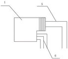
FIG. 1 is a schematic side view of a power parallel connection element in embodiment 1 of the present invention;
FIG. 2 is a schematic view of the connection surface of the parallel connection element of the power supply in embodiment 1 of the present invention;
FIG. 3 is a schematic side view of a parallel connection element for power supply in embodiment 2 of the present invention;
fig. 4 is a schematic view of the connection surface of the parallel connection element of the power supply of embodiment 2 of the present invention.
Detailed Description
Example 1 as shown in fig. 1 and 2, this example is a power parallel connection unit mounted on a power supply to facilitate parallel connection of two power supplies, and is actually soldered to a charge and discharge control circuit board of the power supply, and has a connection surface exposed to a power supply case. As shown in fig. 1, a power parallel connection piece, which is welded on a control circuit board of a power supply, includes a connection seat 1, wherein the connection seat 1 is exposed out of a power supply shell to form a connection surface 2; in practice, a hole can be drilled in a shell of the power supply to expose the connecting surface 2, the connecting surface 2 can also be directly embedded into the shell, two electrode pins 3 which are respectively electrically connected with a power supply output anode circuit and a power supply output cathode circuit on the power supply control circuit board are arranged on the connecting surface 2, and a communication connector 4 which is electrically connected with a communication interface circuit on the power supply control circuit board is also arranged on the connecting surface 2. The communication connector 4 is provided with two contacts which are electrically connected when being connected with a plug according to needs, the two contacts are respectively connected with the second welding pin 6 behind the connecting seat 1, two-wire communication is adopted for the communication interface, the corresponding second welding pin 6 also comprises two welding pins, the two welding pins are welded on a control circuit board of a power supply, one of the two welding pins is connected with one communication IO pin of an MCU on the control circuit board, and the other welding pin is electrically connected with a ground wire on the control circuit board. The first welding leg 5 comprises two welding pins welded on the control circuit board and respectively connected with the positive electrode and the negative electrode of the power supply output. The communication interface is provided with two elastic conductors which are respectively and electrically connected with an output data signal line and a ground wire on the control circuit board. Therefore, the two power supplies can realize handshake communication by utilizing two leads, and realize whether the two power supplies are charged and discharged mutually or not according to the set requirement, or only one power supply with higher voltage is used for supplying power to the load, and when the voltage difference of the two power supplies is smaller than the set threshold value, the two power supplies simultaneously supply power to the load.
In this embodiment, the connection surface 2 is asymmetric, which prevents connection from being mistakenly connected, and if a user wants to connect the wrong connection, the connection surface 2 is not connected. Therefore, if the connector is connected and inserted, the connector cannot rotate, only one situation can be kept, the positive electrode needle 3 and the negative electrode needle 3 cannot be dislocated, and the communication line in the communication connector 4 cannot be connected in a wrong way. In addition, in order to ensure a more compact hand insertion, a snap opening 7 is provided in the communication connector.
Claims (4)
1. A power supply parallel connection piece is welded on a control circuit board of a power supply and comprises a connection seat (1), wherein the connection seat (1) is exposed out of a power supply shell to form a connection surface (2); the method is characterized in that: the connecting surface (2) is provided with two electrode pins (3) which are respectively electrically connected with a power output anode and a cathode circuit on the power control circuit board, and the connecting surface (2) is also provided with a communication connector (4) which is electrically connected with a communication interface circuit on the power control circuit board.
2. The power parallel connection of claim 1, wherein: connecting face (2) include rectangular first half and semicircular latter half, two electrode needle (3) in rectangular first half side by side, communication connector (4) set up in semicircular latter half, two electrode needle (3) and communication connector (4) become three angles of an equilateral triangle.
3. A power supply parallel connection according to claim 1 or 2, characterized in that: the communication connector (4) is provided with two elastic conductors (5) which are respectively and electrically connected with an output data signal line and a ground wire on the control circuit board.
4. A power supply parallel connection according to claim 1 or 2, characterized in that: the communication connector (4) is provided with three elastic conductors (5) which are respectively and electrically connected with an output data signal wire, a clock signal wire and a ground wire on the control circuit board.
Priority Applications (1)
| Application Number | Priority Date | Filing Date | Title |
|---|---|---|---|
| CN202122392989.3U CN216015750U (en) | 2021-09-30 | 2021-09-30 | Power parallel connection spare |
Applications Claiming Priority (1)
| Application Number | Priority Date | Filing Date | Title |
|---|---|---|---|
| CN202122392989.3U CN216015750U (en) | 2021-09-30 | 2021-09-30 | Power parallel connection spare |
Publications (1)
| Publication Number | Publication Date |
|---|---|
| CN216015750U true CN216015750U (en) | 2022-03-11 |
Family
ID=80523242
Family Applications (1)
| Application Number | Title | Priority Date | Filing Date |
|---|---|---|---|
| CN202122392989.3U Active CN216015750U (en) | 2021-09-30 | 2021-09-30 | Power parallel connection spare |
Country Status (1)
| Country | Link |
|---|---|
| CN (1) | CN216015750U (en) |
-
2021
- 2021-09-30 CN CN202122392989.3U patent/CN216015750U/en active Active
Similar Documents
| Publication | Publication Date | Title |
|---|---|---|
| CN107302248B (en) | Electric tool | |
| CN207338783U (en) | A kind of connector | |
| CN216015750U (en) | Power parallel connection spare | |
| CN201100573Y (en) | Emergent lamp | |
| CN208674532U (en) | Power connector | |
| CN216055589U (en) | Power parallel connection cable | |
| CN217848228U (en) | Rechargeable battery, charging device and battery charging system | |
| US11641043B2 (en) | Electric energy storage device and electric tool system | |
| US11855466B2 (en) | Battery charging cable | |
| CN202772340U (en) | Multifunctional connector and electronic device | |
| CN212968403U (en) | Formula electronic connector is inhaled to two contact magnetism and formula electronic connector is inhaled to two contact magnetism | |
| CN106450071B (en) | Battery pack and its with the combination of electric tool and the method for connecting them | |
| CN211789654U (en) | High-power battery connector and hot plug control system | |
| CN210576595U (en) | Charging plug, charging wire and charger | |
| CN213095635U (en) | Charger for electronic float | |
| CN210350032U (en) | Lithium ion battery pack with charger | |
| CN206322883U (en) | Constitutionally stable USB Type C socket connectors | |
| CN201918461U (en) | Battery pack module | |
| CN207732141U (en) | USB A 7Pin quick charge male seats | |
| CN213304541U (en) | Lithium battery power supply patch cord connector | |
| CN215680900U (en) | BMS battery management system with improved connection structure | |
| CN215499752U (en) | Two PCB boards for rifle that charge of mode | |
| CN214278588U (en) | Compatible camera hanging buckle plate | |
| CN213124783U (en) | Positive and negative charging connector | |
| CN218351860U (en) | Anti-surge connecting device and charging equipment |
Legal Events
| Date | Code | Title | Description |
|---|---|---|---|
| GR01 | Patent grant | ||
| GR01 | Patent grant |